EP0454510B1 - Control circuit for a hydraulic double acting cylinder and spool valve for such a circuit - Google Patents
Control circuit for a hydraulic double acting cylinder and spool valve for such a circuit Download PDFInfo
- Publication number
- EP0454510B1 EP0454510B1 EP19910400741 EP91400741A EP0454510B1 EP 0454510 B1 EP0454510 B1 EP 0454510B1 EP 19910400741 EP19910400741 EP 19910400741 EP 91400741 A EP91400741 A EP 91400741A EP 0454510 B1 EP0454510 B1 EP 0454510B1
- Authority
- EP
- European Patent Office
- Prior art keywords
- chamber
- pressure
- fluid
- circuit
- piston
- Prior art date
- Legal status (The legal status is an assumption and is not a legal conclusion. Google has not performed a legal analysis and makes no representation as to the accuracy of the status listed.)
- Expired - Lifetime
Links
Images


Classifications
-
- F—MECHANICAL ENGINEERING; LIGHTING; HEATING; WEAPONS; BLASTING
- F15—FLUID-PRESSURE ACTUATORS; HYDRAULICS OR PNEUMATICS IN GENERAL
- F15B—SYSTEMS ACTING BY MEANS OF FLUIDS IN GENERAL; FLUID-PRESSURE ACTUATORS, e.g. SERVOMOTORS; DETAILS OF FLUID-PRESSURE SYSTEMS, NOT OTHERWISE PROVIDED FOR
- F15B11/00—Servomotor systems without provision for follow-up action; Circuits therefor
- F15B11/02—Systems essentially incorporating special features for controlling the speed or actuating force of an output member
-
- F—MECHANICAL ENGINEERING; LIGHTING; HEATING; WEAPONS; BLASTING
- F15—FLUID-PRESSURE ACTUATORS; HYDRAULICS OR PNEUMATICS IN GENERAL
- F15B—SYSTEMS ACTING BY MEANS OF FLUIDS IN GENERAL; FLUID-PRESSURE ACTUATORS, e.g. SERVOMOTORS; DETAILS OF FLUID-PRESSURE SYSTEMS, NOT OTHERWISE PROVIDED FOR
- F15B2211/00—Circuits for servomotor systems
- F15B2211/20—Fluid pressure source, e.g. accumulator or variable axial piston pump
- F15B2211/205—Systems with pumps
- F15B2211/2053—Type of pump
- F15B2211/20538—Type of pump constant capacity
-
- F—MECHANICAL ENGINEERING; LIGHTING; HEATING; WEAPONS; BLASTING
- F15—FLUID-PRESSURE ACTUATORS; HYDRAULICS OR PNEUMATICS IN GENERAL
- F15B—SYSTEMS ACTING BY MEANS OF FLUIDS IN GENERAL; FLUID-PRESSURE ACTUATORS, e.g. SERVOMOTORS; DETAILS OF FLUID-PRESSURE SYSTEMS, NOT OTHERWISE PROVIDED FOR
- F15B2211/00—Circuits for servomotor systems
- F15B2211/20—Fluid pressure source, e.g. accumulator or variable axial piston pump
- F15B2211/21—Systems with pressure sources other than pumps, e.g. with a pyrotechnical charge
- F15B2211/212—Systems with pressure sources other than pumps, e.g. with a pyrotechnical charge the pressure sources being accumulators
-
- F—MECHANICAL ENGINEERING; LIGHTING; HEATING; WEAPONS; BLASTING
- F15—FLUID-PRESSURE ACTUATORS; HYDRAULICS OR PNEUMATICS IN GENERAL
- F15B—SYSTEMS ACTING BY MEANS OF FLUIDS IN GENERAL; FLUID-PRESSURE ACTUATORS, e.g. SERVOMOTORS; DETAILS OF FLUID-PRESSURE SYSTEMS, NOT OTHERWISE PROVIDED FOR
- F15B2211/00—Circuits for servomotor systems
- F15B2211/30—Directional control
- F15B2211/305—Directional control characterised by the type of valves
- F15B2211/30505—Non-return valves, i.e. check valves
-
- F—MECHANICAL ENGINEERING; LIGHTING; HEATING; WEAPONS; BLASTING
- F15—FLUID-PRESSURE ACTUATORS; HYDRAULICS OR PNEUMATICS IN GENERAL
- F15B—SYSTEMS ACTING BY MEANS OF FLUIDS IN GENERAL; FLUID-PRESSURE ACTUATORS, e.g. SERVOMOTORS; DETAILS OF FLUID-PRESSURE SYSTEMS, NOT OTHERWISE PROVIDED FOR
- F15B2211/00—Circuits for servomotor systems
- F15B2211/40—Flow control
- F15B2211/405—Flow control characterised by the type of flow control means or valve
- F15B2211/40553—Flow control characterised by the type of flow control means or valve with pressure compensating valves
- F15B2211/40561—Flow control characterised by the type of flow control means or valve with pressure compensating valves the pressure compensating valve arranged upstream of the flow control means
-
- F—MECHANICAL ENGINEERING; LIGHTING; HEATING; WEAPONS; BLASTING
- F15—FLUID-PRESSURE ACTUATORS; HYDRAULICS OR PNEUMATICS IN GENERAL
- F15B—SYSTEMS ACTING BY MEANS OF FLUIDS IN GENERAL; FLUID-PRESSURE ACTUATORS, e.g. SERVOMOTORS; DETAILS OF FLUID-PRESSURE SYSTEMS, NOT OTHERWISE PROVIDED FOR
- F15B2211/00—Circuits for servomotor systems
- F15B2211/50—Pressure control
- F15B2211/505—Pressure control characterised by the type of pressure control means
- F15B2211/50509—Pressure control characterised by the type of pressure control means the pressure control means controlling a pressure upstream of the pressure control means
- F15B2211/50518—Pressure control characterised by the type of pressure control means the pressure control means controlling a pressure upstream of the pressure control means using pressure relief valves
- F15B2211/50527—Pressure control characterised by the type of pressure control means the pressure control means controlling a pressure upstream of the pressure control means using pressure relief valves using cross-pressure relief valves
-
- F—MECHANICAL ENGINEERING; LIGHTING; HEATING; WEAPONS; BLASTING
- F15—FLUID-PRESSURE ACTUATORS; HYDRAULICS OR PNEUMATICS IN GENERAL
- F15B—SYSTEMS ACTING BY MEANS OF FLUIDS IN GENERAL; FLUID-PRESSURE ACTUATORS, e.g. SERVOMOTORS; DETAILS OF FLUID-PRESSURE SYSTEMS, NOT OTHERWISE PROVIDED FOR
- F15B2211/00—Circuits for servomotor systems
- F15B2211/50—Pressure control
- F15B2211/505—Pressure control characterised by the type of pressure control means
- F15B2211/50509—Pressure control characterised by the type of pressure control means the pressure control means controlling a pressure upstream of the pressure control means
- F15B2211/50536—Pressure control characterised by the type of pressure control means the pressure control means controlling a pressure upstream of the pressure control means using unloading valves controlling the supply pressure by diverting fluid to the return line
-
- F—MECHANICAL ENGINEERING; LIGHTING; HEATING; WEAPONS; BLASTING
- F15—FLUID-PRESSURE ACTUATORS; HYDRAULICS OR PNEUMATICS IN GENERAL
- F15B—SYSTEMS ACTING BY MEANS OF FLUIDS IN GENERAL; FLUID-PRESSURE ACTUATORS, e.g. SERVOMOTORS; DETAILS OF FLUID-PRESSURE SYSTEMS, NOT OTHERWISE PROVIDED FOR
- F15B2211/00—Circuits for servomotor systems
- F15B2211/50—Pressure control
- F15B2211/515—Pressure control characterised by the connections of the pressure control means in the circuit
- F15B2211/5153—Pressure control characterised by the connections of the pressure control means in the circuit being connected to an output member and a directional control valve
- F15B2211/5154—Pressure control characterised by the connections of the pressure control means in the circuit being connected to an output member and a directional control valve being connected to multiple ports of an output member
-
- F—MECHANICAL ENGINEERING; LIGHTING; HEATING; WEAPONS; BLASTING
- F15—FLUID-PRESSURE ACTUATORS; HYDRAULICS OR PNEUMATICS IN GENERAL
- F15B—SYSTEMS ACTING BY MEANS OF FLUIDS IN GENERAL; FLUID-PRESSURE ACTUATORS, e.g. SERVOMOTORS; DETAILS OF FLUID-PRESSURE SYSTEMS, NOT OTHERWISE PROVIDED FOR
- F15B2211/00—Circuits for servomotor systems
- F15B2211/50—Pressure control
- F15B2211/515—Pressure control characterised by the connections of the pressure control means in the circuit
- F15B2211/5158—Pressure control characterised by the connections of the pressure control means in the circuit being connected to a pressure source and an output member
-
- F—MECHANICAL ENGINEERING; LIGHTING; HEATING; WEAPONS; BLASTING
- F15—FLUID-PRESSURE ACTUATORS; HYDRAULICS OR PNEUMATICS IN GENERAL
- F15B—SYSTEMS ACTING BY MEANS OF FLUIDS IN GENERAL; FLUID-PRESSURE ACTUATORS, e.g. SERVOMOTORS; DETAILS OF FLUID-PRESSURE SYSTEMS, NOT OTHERWISE PROVIDED FOR
- F15B2211/00—Circuits for servomotor systems
- F15B2211/50—Pressure control
- F15B2211/52—Pressure control characterised by the type of actuation
- F15B2211/526—Pressure control characterised by the type of actuation electrically or electronically
-
- F—MECHANICAL ENGINEERING; LIGHTING; HEATING; WEAPONS; BLASTING
- F15—FLUID-PRESSURE ACTUATORS; HYDRAULICS OR PNEUMATICS IN GENERAL
- F15B—SYSTEMS ACTING BY MEANS OF FLUIDS IN GENERAL; FLUID-PRESSURE ACTUATORS, e.g. SERVOMOTORS; DETAILS OF FLUID-PRESSURE SYSTEMS, NOT OTHERWISE PROVIDED FOR
- F15B2211/00—Circuits for servomotor systems
- F15B2211/60—Circuit components or control therefor
- F15B2211/665—Methods of control using electronic components
- F15B2211/6653—Pressure control
-
- F—MECHANICAL ENGINEERING; LIGHTING; HEATING; WEAPONS; BLASTING
- F15—FLUID-PRESSURE ACTUATORS; HYDRAULICS OR PNEUMATICS IN GENERAL
- F15B—SYSTEMS ACTING BY MEANS OF FLUIDS IN GENERAL; FLUID-PRESSURE ACTUATORS, e.g. SERVOMOTORS; DETAILS OF FLUID-PRESSURE SYSTEMS, NOT OTHERWISE PROVIDED FOR
- F15B2211/00—Circuits for servomotor systems
- F15B2211/60—Circuit components or control therefor
- F15B2211/665—Methods of control using electronic components
- F15B2211/6654—Flow rate control
-
- F—MECHANICAL ENGINEERING; LIGHTING; HEATING; WEAPONS; BLASTING
- F15—FLUID-PRESSURE ACTUATORS; HYDRAULICS OR PNEUMATICS IN GENERAL
- F15B—SYSTEMS ACTING BY MEANS OF FLUIDS IN GENERAL; FLUID-PRESSURE ACTUATORS, e.g. SERVOMOTORS; DETAILS OF FLUID-PRESSURE SYSTEMS, NOT OTHERWISE PROVIDED FOR
- F15B2211/00—Circuits for servomotor systems
- F15B2211/70—Output members, e.g. hydraulic motors or cylinders or control therefor
- F15B2211/705—Output members, e.g. hydraulic motors or cylinders or control therefor characterised by the type of output members or actuators
- F15B2211/7051—Linear output members
- F15B2211/7053—Double-acting output members
- F15B2211/7054—Having equal piston areas
Definitions
- the present invention is in the field of controlling hydraulic cylinders.
- the invention relates to a control circuit for a double-acting hydraulic cylinder consisting of a piston connected to an outlet rod and separating a cylinder into two chambers, the circuit comprising a source of pressurized fluid, a system distribution alternately placing one of the control chambers or chamber in communication with the source of pressurized fluid and the other controlled chamber or chamber in communication with a reservoir of low pressure fluid to control the movement of the piston of the jack.
- a circuit of this type is for example functionally described in US Pat. No. 4,040,439, which more specifically relates to a hydraulic buffer circuit intended to avoid the occurrence of transient pressures of significant value.
- Hydraulic cylinders are well-known components which transform the hydraulic energy they receive into mechanical energy, the latter possibly being considerable.
- Double-acting cylinders consist of a cylinder in which slides a piston dividing the cylinder into two chambers, the piston being connected to an outlet rod.
- a distribution system is controlled to admit fluid under pressure into one of the chambers, while the fluid contained in the other chamber is discharged into a low pressure tank, from which a high pressure pump is drawn, to allow the piston to move in the cylinder.
- the object of the invention is therefore to provide in the control circuit an auxiliary circuit which recovers the outlet fluid from the jack when its pressure exceeds a predetermined value, an auxiliary circuit which is simple and reliable in design and does not cause an increase. significant cost of the actuator control circuit.
- control circuit comprises an auxiliary circuit for prohibiting communication between the controlled chamber and the reservoir and interrupting the communication between the control chamber and the source of pressurized fluid when the pressure of the fluid in the controlled chamber reaches a predetermined value.
- the auxiliary circuit makes it possible to establish communication between the controlled chamber and the control chamber when the pressure of the fluid in the controlled chamber exceeds the predetermined value.
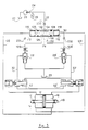
- Figure 3 shows a theoretical diagram of a control circuit of a double-acting hydraulic cylinder according to a second embodiment of the invention.
- FIG. 1 shows a known control circuit for a double-acting cylinder 10 divided by a piston 12 into two chambers 14 and 16, of variable volume.
- the piston is mounted on a rod 18.
- the hydraulic supply is provided by a pump 20, connected to a supply line 22 through a non-return valve 24.
- the supply line 22 is also connected to an accumulator of pressure 26.
- the control circuit comprises, for the chamber 14, a three-way solenoid valve 28, which puts a line 30 in communication, either with the high pressure line 22, or with a reservoir 25. When the solenoid valve 28 is not energized , it puts the line 30 in communication with the reservoir 25.
- the control circuit likewise comprises, for the chamber 16, a three-way solenoid valve 28 ′ which puts a line 30 ′ into communication, that is to say with the high pressure line 22, either with the reservoir 25. When the solenoid valve 28 ′ is not energized, it puts the line 30 ′ in communication with the reservoir 25.
- the control circuit can be controlled by a computer or a microprocessor (not shown) which controls each of the solenoid valves 28,28 ′ and the pump 20 with, for example, a servo-control of the jack in position.
- Line 30 is connected, through a non-return valve 32, to line 34 supplying the chamber 14.
- Line 34 is also connected to the reservoir via a controlled valve 36.
- This valve is controlled by the pressure existing in line 30 ′, symmetrical with line 30, in the circuit corresponding to the second chamber 16 of the jack. If the solenoid valve 28 ′, symmetrical with the solenoid valve 28, which controls the pressure in the second chamber 16, is controlled, the pressure in the line 30 ′ causes the valve 36 to open and the chamber 14 to be turned on. tank. Conversely, if the solenoid valve 28 is energized, the pressure in the line 30 controls the opening of a valve 36 ′ which places the chamber 16 in the reservoir. Thus, the chambers 14 and 16 are alternately one under pressure, the other at the tank.
- the two solenoid valves 28,28 ′ are at rest, the two chambers 14 and 16 are kept isolated by closing the valves 36,36 ′ and the non-return valves 32,32 '.
- the invention proposes to have in the control circuit an auxiliary circuit which comes into action as soon as the pressure in the controlled chamber exceeds that of the control chamber by a certain value.
- FIG 2 shows a control circuit according to the invention, in which the elements identical to those in Figure 1 have the same reference numerals.
- the control circuit is supplied as before by the pump 20 connected to the supply line 22 through a non-return valve 24, the line 22 being connected to a pressure accumulator 26 and supplying the solenoid valves 28 and 28 ′ through of a dispenser 50 which will be described later.
- the pipe 30 at the outlet of the solenoid valve 28 is connected to the pipe 34 for supplying the chamber 14 via a controlled valve 52.
- This valve 52 comprises a first chamber 54, into which the pipe 34 opens, containing a ball 56 loaded by a spring 58 towards a rest position where it prohibits communication to a second chamber 60 into which the pipe 30 opens.
- the second chamber 60 is delimited by a piston 62 carrying on one side a needle 64 susceptible to lift the ball 56 from its seat when the pressure in a third chamber 66 on the other side of the piston 62 causes the latter to move against the return spring 58 and the pressure prevailing in the chamber 54.
- the section of the piston 62 is identical to that of the seat of the ball 56.
- the third chamber 66 is in communication with the line 30 ′ symmetrical of the line 30 in the supply circuit of the chamber 16. It can thus be seen that the valve 52 is controlled by the pressure existing in the circuit 30 'corresponding to the second chamber 16 of the jack.
- This latter circuit comprises a valve 52 ′ identical to valve 52, its elements bearing the same numerical references assigned a "premium" therefore do not require a detailed description.
- the solenoid valve 28 ′ is energized, the solenoid valve 28 is left to stand.
- the pressure in line 22 is therefore transmitted through the distributor 50 and the solenoid valve 28 ′ in line 30 ′ and in the second chamber 60 '.
- the pressure in the pipe 30 ′ is transmitted to the third chamber 66 of the valve 52, which has the effect of making move the piston 62 to the left considering Figure 2 and therefore lift the ball 56 from its seat, thus establishing communication between the first and second chambers 54 and 60, and therefore between the lines 30 and 14.
- the solenoid valve 28 not being excited, the pipe 30 communicates with the reservoir 25, and consequently the chamber 14 of the jack is therefore connected to the reservoir.
- the piston 12 can therefore move to the left.
- the chambers 14 and 16 are alternately one under pressure, the other at the reservoir. If, however, the two solenoid valves 28, 28 ′ are at rest, the two chambers 14 and 16 are kept isolated by closing the valves 52 and 52 ′.
- the pressure in the chamber 16 may be caused to rise for the reasons mentioned above. In this case the external force is driving. It is then that the auxiliary circuit according to the invention comes into play.
- the auxiliary circuit mainly comprises the distributor 50 disposed between the high pressure line 22 and the solenoid valves 28 and 28 '.
- the distributor 50 consists of a drawer 100 sliding in a bore 102.
- This drawer has a central groove 104 between two bearing surfaces 106 and 108 cooperating in sealed manner with the bore 102 to divide it into three chambers: an end chamber 110,112 on each side of the drawer and an annular central chamber 114 defined by the central groove 104.
- the drawer 100 is symmetrical and is held in the rest position in the middle of the bore 102 by springs 116 and 118 of the same rigidity on each side of the drawer.
- the auxiliary circuit also comprises a line 120 connecting the chamber 110 with the line 34 ′, and a line 122 connecting the chamber 112 to the line 34.
- the high pressure line 22 opens into the central chamber 114 through an orifice which does not is never covered by staves 106 and 108.
- the bearing surface 106 cooperates with two orifices 124 and 126 so that the orifice 126 is uncovered and opens into the central chamber 114 when the drawer is in its central rest position or moved to the left, and is covered when the drawer 100 moves to the right (in Figure 2), while the orifice 124 is covered by the drawer in its central rest position or moved to the left, and uncovered and opens into the chamber 110 when the drawer is moved towards the right (in Figure 2).
- the two orifices 124 and 126 both communicate with a line 128 connected to the solenoid valve 28.
- the bearing surface 108 cooperates with two orifices 130 and 132 so that the orifice 130 is uncovered and opens into the central chamber 114 when the drawer is in its central rest position or moved to the right, and is covered when the drawer 100 moves to the left (in Figure 2), while the orifice 132 is covered by the drawer in its central rest position or moved to the right, and uncovered and opens into the chamber 112 when the drawer is moved to the left (in Figure 2).
- the two orifices 130 and 132 both communicate with a line 128 'connected to the solenoid valve 28'.
- the pressure in the pipe 30 is transmitted to the third chamber 66 ′ of the valve 52 ′, which has the effect of causing the piston 62 ′ to move to the right when considering Figure 2 and therefore lifting the ball 56 ′ from its seat, thus establishing communication between the first and second chambers 54 ′ and 60 ′, and therefore between the pipes 30 ′ and 34 '. Since the solenoid valve 28 ′ is not energized, the pipe 30 ′ communicates with the reservoir 25, and consequently the chamber 16 of the jack is therefore connected to the reservoir. The piston 12 can therefore move to the right. As the chamber 16 is connected to the reservoir, the same applies to the chamber 110 of the distributor 50 via the conduit 120. On the other hand, the pressure prevailing in the chamber 14 is transmitted by the conduit 122, to the chamber 112 of the distributor 50.
- the pressure imbalance on the two sides of the drawer 100 causes it to move to the left. In doing so, the range 106 continues to cover the orifice 124 and to discover the orifice 126.
- the solenoid valve 28 therefore continues to be supplied and the supply circuit of the chamber 14 is unchanged.
- the range 108 when it will cover the orifice 130 and discover the orifice 132.
- the pressure in the chamber 14 is therefore transmitted through the line 122 and the chamber 112 to the solenoid valve 28 ′, which is closed. We see that nothing changes in the return circuit of room 16.
- the pressure in the chamber 16 is high, for example because the rod 18 is pushed to the right by an external force and becomes greater than the pressure in the chamber 14, the imbalance of the pressures in the chambers 14 and 16 is transmitted to the chambers 110 and 112 on each side of the drawer 100 and causes the pressure in the chamber 110 to be greater than that prevailing in the chamber 112, the drawer 100 moves to the right in FIG. 2.
- the slide covers the orifice 126, thus interrupting the possibility of supply of pressurized fluid to the solenoid valve 28 by the source of pressurized fluid through the line 22, and discovers the orifice 124, and therefore allows the fluid in the controlled chamber 16 , under a pressure higher than that of the fluid in the control chamber 14, to be reinjected towards the solenoid valve 28 then towards the chamber 14 if the solenoid valve is energized.
- the pressure in the chamber 16 is transmitted to the chamber 54 ′ of the valve 52 ′, the left face of the piston 62 ′ is subjected in the chamber 66 ′ to the pressure of the chamber 14 via the line 30 and the chamber 60 of valve 52, always subjected to the pressure of chamber 14 of the jack.
- the section of the piston 62 ' being equal to the section of the seat of the ball and the pressure in the chamber 54 ′, equal to that of the chamber 16, being slightly greater than or equal to the pressure in the chamber 66 ′, equal to that of the chamber 14, the ball 56 ′ does not lift and prohibits the communication of the chamber 16 with the reservoir 25.
- FIG. 3 a second embodiment of the auxiliary circuit according to the invention.
- the distributor 50 is identical to that of FIG. 2, except that the surfaces 106 and 108 of the drawer 100 each cooperate with a single port 126 and 130 respectively.
- the range 106 cooperates with the orifice 126 so that the orifice 126 is uncovered and opens into the chamber 114 when the drawer is in its rest position or moved to the left ( Figure 3) and is covered when the drawer 100 is moved to the right.
- the bearing surface 108 cooperates with the orifice 130 so that it is uncovered and opens into the cavity 114 when the drawer is in the central position or moved to the right in FIG. 3 and is covered when the drawer is moved towards left.
- Line 120 is connected to line 128 via a non-return valve 201, just as line 122 is connected to line 128 ′ via a non-return valve 202.
- the slide 100 In normal operation, if the difference between the pressures in the chambers 14 and 16 of the jack, and therefore in the chambers 112 and 110 respectively, is small, the slide 100 remains in the central position and the solenoid valves 28 and 28 ′ can be supplied by the high pressure line 22 via the chamber 114. If for example, the solenoid valve 28 ′ is energized and the external force is resistant, the piston 12 of the jack moves to the left under the effect of the increase in pressure in the chamber 16 as described above, which increase in pressure is also transmitted to the chamber 110 of the distributor 50. The slide 100 therefore moves to the right, the bearing 106 then covers the orifice 126, while the orifice 130 remains uncovered and allows the supply of the solenoid valve 28 '.
- the non-return valve 202 prevents the communication of pressurized fluid to the chamber 112 of the distributor and to the chamber 14 of the jack.
- a non-return valve 203 can be provided on the high pressure line 22 to prevent a sudden rise in pressure in the chamber 16 from being transmitted, via the lines 120 and 128, the orifice 126 and the chamber 114, to the hydraulic supply device 20,26, before the drawer 100 has moved. The hydraulic blocking of the jack is then ensured. Likewise, the non-return valve 203 ensures the hydraulic blocking of the jack in the case where the high pressure supply system 20-26 is at rest, or is broken down.
- a control circuit has therefore been produced in accordance with the invention for a double-acting cylinder of simple and reliable design and without significant additional cost. Indeed, in all cases, the movement of the piston of the jack is controlled by the excitation of a single solenoid valve 28 or 28 '.
- the distributor 50 is sensitive to the difference in pressures in the chambers 14 and 16 of the jack, that is to say that it detects the direction of the external forces to which the rod of the jack is subjected. Depending on the direction detected, it will allow either the supply of pressurized fluid to the control chamber by the high pressure hydraulic supply device 20,26 if the external forces are resistant or weak, or the recovery of the pressurized fluid in the controlled chamber to supply it to the control chamber if the external forces are driving. An energy recovery is therefore obtained which would otherwise be lost in the low pressure tank 25, and a reduction in the consumption of hydraulic fluid of the control circuit.
- Such a device will find application in all active hydraulic systems, that is to say irreversible systems which use a clean energy source, to transform them into reactive systems according to the external conditions to which they are subjected.
Description
La présente invention est du domaine de la commande de vérins hydrauliques.The present invention is in the field of controlling hydraulic cylinders.
Plus précisément, l'invention concerne un circuit de commande d'un vérin hydraulique à double effet constitué d'un piston relié à une tige de sortie et séparant un cylindre en deux chambres, le circuit comportant une source de fluide sous pression, un système de distribution mettant alternativement une des chambres ou chambre de commande en communication avec la source de fluide sous pression et l'autre chambre ou chambre commandée en communication avec un réservoir de fluide sous basse pression pour commander le mouvement du piston du vérin.More specifically, the invention relates to a control circuit for a double-acting hydraulic cylinder consisting of a piston connected to an outlet rod and separating a cylinder into two chambers, the circuit comprising a source of pressurized fluid, a system distribution alternately placing one of the control chambers or chamber in communication with the source of pressurized fluid and the other controlled chamber or chamber in communication with a reservoir of low pressure fluid to control the movement of the piston of the jack.
Un circuit de ce type est par exemple fonctionnellement décrit dans le brevet US 4 040 439, qui concerne plus spécifiquement un circuit hydraulique tampon destiné à éviter l'apparition de pressions transitoires de valeur importante.A circuit of this type is for example functionally described in US Pat. No. 4,040,439, which more specifically relates to a hydraulic buffer circuit intended to avoid the occurrence of transient pressures of significant value.
Les vérins hydrauliques sont des composants bien connus qui transforment l'énergie hydraulique qu'ils reçoivent en énergie mécanique, cette dernière pouvant être considérable. Les vérins a double effet sont constitués d'un cylindre dans lequel coulisse un piston divisant le cylindre en deux chambres, le piston étant relié à une tige de sortie.Hydraulic cylinders are well-known components which transform the hydraulic energy they receive into mechanical energy, the latter possibly being considerable. Double-acting cylinders consist of a cylinder in which slides a piston dividing the cylinder into two chambers, the piston being connected to an outlet rod.
Lorsque l'on désire que le vérin fournisse un travail dans un sens, de façon classique, on commande un système de distribution pour admettre du fluide sous pression dans une des chambres, tandis que le fluide contenu dans l'autre chambre est évacué dans un réservoir à basse pression, dans lequel puise une pompe haute pression, pour permettre au piston de se déplacer dans le cylindre.When it is desired that the jack provide work in one direction, in a conventional manner, a distribution system is controlled to admit fluid under pressure into one of the chambers, while the fluid contained in the other chamber is discharged into a low pressure tank, from which a high pressure pump is drawn, to allow the piston to move in the cylinder.
Il peut se présenter des cas où le vérin est déjà soumis à un effort extérieur tendant à faire se mouvoir le piston dans un sens, et que l'on désire également que le vérin se déplace dans ce même sens. C'est par exemple le cas où, après avoir été manoeuvré, on désire que le vérin reprenne sa position de repos, correspondant par exemple à la position médiane du piston dans le cylindre, et où l'effort extérieur auquel est soumis le vérin est fourni par des systèmes de recentrage du piston. Généralement, le mouvement du piston est là encore obtenu de façon classique par admission de fluide sous pression dans une des chambres et évacuation du fluide de l'autre chambre vers le réservoir.There may be cases where the cylinder is already subjected to an external force tending to cause the piston to move in one direction, and it is also desired that the cylinder moves in this same direction. This is for example the case where, after being maneuvered, it is desired that the cylinder return to its rest position, corresponding for example to the median position of the piston in the cylinder, and where the external force to which the cylinder is subjected is supplied by piston refocusing systems. Generally, the movement of the piston is again obtained in a conventional manner by admission of pressurized fluid into one of the chambers and evacuation of the fluid from the other chamber to the reservoir.
Quand les efforts extérieurs sont résistants, on conçoit bien que la liaison d'une des chambres avec le réservoir a pour but de ne pas entraver le fonctionnement du vérin. Cependant, dans les cas cités plus haut où le vérin est déjà sollicité dans le sens où on désire que se produise le mouvement du piston, c'est à dire quand les efforts extérieurs sont moteurs, la chambre que classiquement on relie au réservoir se trouve sous pression du fait même de la sollicitation extérieure. Le fait de rejeter au réservoir du fluide sous pression constitue donc manifestement une perte d'énergie, qui peut être importante selon l'installation commandée par le vérin.When the external forces are resistant, it is understandable that the connection of one of the chambers with the tank is intended not to hinder the operation of the jack. However, in the cases mentioned above where the cylinder is already stressed in the sense that it is desired that produce the movement of the piston, that is to say when the external forces are driving, the chamber which conventionally is connected to the reservoir is under pressure by the very fact of the external stress. Rejecting pressurized fluid to the tank therefore clearly constitutes a loss of energy, which can be significant depending on the installation controlled by the jack.
L'invention a donc pour objet de prévoir dans le circuit de commande un circuit auxiliaire qui récupère le fluide de sortie du vérin quand sa pression dépasse une valeur prédéterminée, circuit auxiliaire qui soit de conception simple et fiable et n'entraîne pas d'augmentation importante du coût du circuit de commande du vérin.The object of the invention is therefore to provide in the control circuit an auxiliary circuit which recovers the outlet fluid from the jack when its pressure exceeds a predetermined value, an auxiliary circuit which is simple and reliable in design and does not cause an increase. significant cost of the actuator control circuit.
Selon l'invention, le circuit de commande comprend un circuit auxiliaire pour interdire la communication entre la chambre commandée et le réservoir et interrompre la communication entre la chambre de commande et la source de fluide sous pression lorsque la pression du fluide dans la chambre commandée atteint une valeur prédéterminée.According to the invention, the control circuit comprises an auxiliary circuit for prohibiting communication between the controlled chamber and the reservoir and interrupting the communication between the control chamber and the source of pressurized fluid when the pressure of the fluid in the controlled chamber reaches a predetermined value.
Selon une caractéristique avantageuse de l'invention, le circuit auxiliaire permet d'établir la communication entre la chambre commandée et la chambre de commande lorsque la pression du fluide dans la chambre commandée dépasse la valeur prédéterminée.According to an advantageous characteristic of the invention, the auxiliary circuit makes it possible to establish communication between the controlled chamber and the control chamber when the pressure of the fluid in the controlled chamber exceeds the predetermined value.
D'autres caractéristiques et avantages de la présente invention ressortiront de la description suivante de deux modes de réalisation donnés à titre d'exemple, faite en relation avec les dessins annexés sur lesquels :
- la Figure 1 représente un schéma théorique d'un circuit de commande d'un vérin hydraulique à double effet de l'art antérieur,
- la Figure 2 représente un schéma théorique d'un circuit de commande d'un vérin hydraulique à double effet conforme à un mode de réalisation de l'invention,
- FIG. 1 represents a theoretical diagram of a control circuit of a double-acting hydraulic cylinder of the prior art,
- Figure 2 represents a theoretical diagram of a circuit of control of a double-acting hydraulic cylinder in accordance with an embodiment of the invention,
La Figure 3 représente un schéma théorique d'un circuit de commande d'un vérin hydraulique à double effet conforme à un second mode de réalisation de l'invention.Figure 3 shows a theoretical diagram of a control circuit of a double-acting hydraulic cylinder according to a second embodiment of the invention.
On a représenté sur la Figure 1 un circuit de commande connu pour un vérin à double effet 10 divisé par un piston 12 en deux chambres 14 et 16, de volume variable. Le piston est monté sur une tige 18. L'alimentation hydraulique est assurée par une pompe 20, reliée à une conduite d'alimentation 22 à travers un clapet anti-retour 24. La conduite d'alimentation 22 est également reliée à un accumulateur de pression 26.FIG. 1 shows a known control circuit for a double-acting
Le circuit de commande comprend, pour la chambre 14, une électrovanne à trois voies 28, qui met en communication une conduite 30, soit avec la conduite haute pression 22, soit avec un réservoir 25. Lorsque l'électrovanne 28 n'est pas excitée, elle met la conduite 30 en communication avec le réservoir 25. Le circuit de commande comprend de même, pour la chambre 16, une électrovanne à trois voie 28′ qui met en communication une conduite 30′, soit avec la conduite haute pression 22, soit avec le réservoir 25. Lorsque l'électrovanne 28′ n'est pas excitée, elle met la conduite 30′ en communication avec le réservoir 25.The control circuit comprises, for the
Le circuit de commande peut être commandé par un calculateur ou un microprocesseur (non représenté) qui commande chacune des électrovalves 28,28′ et la pompe 20 avec, par exemple, un asservissement du vérin en position .The control circuit can be controlled by a computer or a microprocessor (not shown) which controls each of the
La conduite 30 est reliée, à travers un clapet anti-retour 32, à la conduite 34 d'alimentation de la chambre 14. La conduite 34 est également reliée au réservoir par l'intermédiaire d'un clapet commandé 36. Ce clapet est commandé par la pression existant dans la conduite 30′, symétrique de la conduite 30, dans le circuit correspondant à la seconde chambre 16 du vérin. Si l'électrovanne 28′, symétrique de l'électrovanne 28, qui commande la pression dans la seconde chambre 16, est commandée, la pression dans la conduite 30′ fait que le clapet 36 s'ouvre et que la chambre 14 est mise au réservoir. Réciproquement, si l'électrovanne 28 est excitée, la pression dans la conduite 30 commande l'ouverture d'un clapet 36′ qui met au réservoir la chambre 16. Ainsi, les chambres 14 et 16 sont alternativement l'une sous pression, l'autre au réservoir. Si cependant les deux électrovannes 28,28′ sont au repos, les deux chambres 14 et 16 sont maintenues isolées par la fermeture des clapets 36,36′ et des clapets anti-retour 32,32'. Au cas où, par exemple, pendant une manoeuvre, la pression chuterait dans la conduite haute pression 22 cela entraînerait la fermeture du clapet 36 ou 36' qui serait ouvert et, par conséquent, l'isolement automatique des chambres 14 et 16, et l'immobilisation du piston 12 dans la position qu'il occupait au moment où est survenue la défaillance hydraulique.
En fonctionnement normal, par exemple après une manoeuvre qui a amené le piston 12 vers la gauche sur la Figure 1, si on désire ramener le piston 12 vers la droite, on a vu ci-dessus qu'il suffit d'exciter l'électrovanne 28 pour admettre du fluide sous pression dans la chambre 14, qu'on appellera chambre de commande, et pour relier la chambre 16, qu'on appellera chambre commandée, au réservoir, ce qui provoque bien le mouvement désiré du piston 12 vers la droite. Cependant, la tige 18 peut elle-même être aussi soumise à des sollicitations extérieures tendant à la faire aussi se mouvoir vers la droite. Ces sollicitations peuvent provenir, par exemple, des systèmes de rappel de direction si le vérin 10 est inclus dans un système de commande hydraulique de direction d'un véhicule à direction assistée, des rebonds de suspension si le vérin 10 est inclus dans un système de suspension hydraulique de véhicule, ou d'une manière générale de l'action du milieu extérieur sur le vérin. Dans ces cas, avant la commande, la pression du fluide dans la chambre commandée 16 n'est pas celle du réservoir à basse pression 25, mais s'élève à des valeurs bien supérieures, en particulier supérieures à celle du fluide dans la chambre de commande 14. Le fait de rejeter au réservoir du fluide sous pression entraîne une consommation inutile de fluide hydraulique, et évidemment une déperdition d'énergie.In normal operation, for example after an operation which has brought the
Pour remédier à cette situation, l'invention propose de disposer dans le circuit de commande un circuit auxiliaire qui entre en action dès que la pression dans la chambre commandée dépasse celle de la chambre de commande d'une certaine valeur.To remedy this situation, the invention proposes to have in the control circuit an auxiliary circuit which comes into action as soon as the pressure in the controlled chamber exceeds that of the control chamber by a certain value.
On a représenté sur la Figure 2 un circuit de commande conforme à l'invention, dans lequel les éléments identiques à ceux à la Figure 1 portent les mêmes références numériques.Figure 2 shows a control circuit according to the invention, in which the elements identical to those in Figure 1 have the same reference numerals.
Le circuit de commande est alimenté comme précédemment par la pompe 20 reliée à la conduite d'alimentation 22 à travers un clapet anti-retour 24, la conduite 22 étant reliée à un accumulateur de pression 26 et alimentant les électrovannes 28 et 28′ au travers d'un distributeur 50 qu'on décrira par la suite.The control circuit is supplied as before by the
La conduite 30 en sortie de l'électrovalve 28 est reliée à la conduite 34 d'alimentation de la chambre 14 par l'intermédiaire d'un clapet commandé 52. Ce clapet 52 comporte une première chambre 54, dans laquelle débouche la conduite 34, contenant une bille 56 chargée par un ressort 58 vers une position de repos où elle interdit la communication vers une deuxième chambre 60 dans laquelle débouche la conduite 30. La deuxième chambre 60 est délimitée par un piston 62 portant d'un côté un pointeau 64 susceptible de soulever la bille 56 de son siège lorsque la pression dans une troisième chambre 66 de l'autre côté du piston 62 fait mouvoir ce dernier à l'encontre du ressort de rappel 58 et de la pression régnant dans la chambre 54. La section du piston 62 est identique à celle du siège de la bille 56. La troisième chambre 66 est en communication avec la conduite 30′ symétrique de la conduite 30 dans le circuit d'alimentation de la chambre 16. On voit ainsi que le clapet 52 est commandé par la pression existant dans le circuit 30' correspondant à la seconde chambre 16 du vérin. Ce dernier circuit comporte un clapet 52′ identique au clapet 52, ses éléments portant les mêmes références numériques affectées d'un "prime" ne nécessitent donc pas de description détaillée.The
Si on désire par exemple que le piston du vérin se déplace vers la gauche en considérant la Figure 2, la pompe 20 est mise en oeuvre, l'électrovanne 28′ est excitée, l'électrovanne 28 est laissée au repos. La pression dans la conduite 22 est donc transmise à travers le distributeur 50 et l'électrovanne 28′ dans la conduite 30′ et dans la deuxième chambre 60'. La bille 56' se soulève sous l'action de cette pression qui est alors transmise par la conduite 34′ à la chambre 16 du vérin. Simultanément, la pression dans la conduite 30′ est transmise à la troisième chambre 66 du clapet 52, ce qui a pour effet de faire se mouvoir le piston 62 vers la gauche en considérant la Figure 2 et donc de soulever la bille 56 de son siège, établissant ainsi la communication entre les première et seconde chambres 54 et 60, et donc entre les conduites 30 et 14. L'électrovanne 28 n'étant pas excitée, la conduite 30 communique avec le réservoir 25, et par voie de conséquence la chambre 14 du vérin se trouve donc reliée au réservoir. Le piston 12 peut donc se déplacer vers la gauche.If, for example, it is desired that the piston of the jack moves to the left, considering FIG. 2, the
Ainsi, les chambres 14 et 16 sont alternativement l'une sous pression, l'autre au réservoir. Si cependant les deux électrovannes 28,28′ sont au repos, les deux chambres 14 et 16 sont maintenues isolées par la fermeture des clapets 52 et 52'.Thus, the
On notera au passage que cette disposition avantageuse des clapets commandés 52 et 52′ permet de se dispenser de disposer les clapets anti-retour 32 et 32′ de la Figure 1 dans les conduites 30 et 30'. Au cas où, par exemple, pendant une manoeuvre du vérin, la pression chuterait dans la conduite haute pression 22, cela entraînerait la fermeture du clapet 52 ou 52′ qui serait ouvert et, par conséquent, l'isolement automatique des chambres 14 et 16, et donc l'immobilisation du piston 12 dans la position qu'il occupait au moment où l'avarie dans le circuit hydraulique est apparue.It will be noted in passing that this advantageous arrangement of the controlled
Après la manoeuvre qui a été décrite plus haut pour déplacer le piston vers la gauche, le retour du piston vers la droite sera provoqué de façon symétrique par excitation de l'électrovanne 28 et ne nécessite pas de description détaillée.After the maneuver which has been described above to move the piston to the left, the return of the piston to the right will be caused symmetrically by excitation of the
Au cours de cette manoeuvre vers la droite, la pression dans la chambre 16 peut être amenée à s'élever pour les raisons évoquées plus haut. Dans ce cas l'effort extérieur est moteur. C'est alors qu'entre en jeu le circuit auxiliaire selon l'invention.During this maneuver to the right, the pressure in the
Le circuit auxiliaire comprend principalement le distributeur 50 disposé entre la conduite haute pression 22 et les électrovannes 28 et 28'. Le distributeur 50 est constitué d'un tiroir 100 coulissant dans un alésage 102. Ce tiroir comporte une gorge centrale 104 entre deux portées 106 et 108 coopérant de façon étanche avec l'alésage 102 pour le diviser en trois chambres : une chambre d'extrémité 110,112 de chaque côté du tiroir et une chambre centrale annulaire 114 définie par la gorge centrale 104. Le tiroir 100 est symétrique et est maintenu en position de repos au milieu de l'alésage 102 par des ressorts 116 et 118 de même rigidité de chaque côté du tiroir.The auxiliary circuit mainly comprises the
Le circuit auxiliaire comprend également une conduite 120 mettant en communication la chambre 110 avec la conduite 34′, et une conduite 122 reliant la chambre 112 à la conduite 34. La conduite haute pression 22 débouche dans la chambre centrale 114 par un orifice qui n'est jamais recouvert par les portées 106 et 108.The auxiliary circuit also comprises a
La portée 106 coopère avec deux orifices 124 et 126 de telle manière que l'orifice 126 soit découvert et débouche dans la chambre centrale 114 lorsque le tiroir est dans sa position centrale de repos ou déplacé vers la gauche, et soit recouvert lorsque le tiroir 100 se déplace vers la droite (sur la Figure 2), tandis que l'orifice 124 est recouvert par le tiroir dans sa position centrale de repos ou déplacé vers la gauche, et découvert et débouchant dans la chambre 110 lorsque le tiroir est déplacé vers la droite (sur la Figure 2). Les deux orifices 124 et 126 communiquent tous deux avec une conduite 128 raccordée à l'électrovanne 28.The bearing
De même, la portée 108 coopère avec deux orifices 130 et 132 de telle manière que l'orifice 130 soit découvert et débouche dans la chambre centrale 114 lorsque le tiroir est dans sa position centrale de repos ou déplacé vers la droite, et soit recouvert lorsque le tiroir 100 se déplace vers la gauche (sur la Figure 2), tandis que l'orifice 132 est recouvert par le tiroir dans sa position centrale de repos ou déplacé vers la droite, et découvert et débouchant dans la chambre 112 lorsque le tiroir est déplacé vers la gauche (sur la Figure 2). Les deux orifices 130 et 132 communiquent tous deux avec une conduite 128' raccordée à l'électrovanne 28'.Similarly, the bearing
En fonctionnement normal, si on désire par exemple que le piston 12 du vérin se déplace vers la droite (sur la Figure 2), la pompe 20 est mise en oeuvre et la pression dans la conduite 22 est transmise à la chambre centrale 114 du distributeur 50. Si par exemple ce dernier est au repos à cet instant, les orifices 126 et 130 sont découverts, et le fluide sous pression parvient donc aux électrovannes 28 et 28'. Si seule l'électrovanne 28 est excitée, la pression est transmise par la conduite 30 dans la deuxième chambre 60 du clapet commandé 52. La bille 56 se soulève sous l'action de cette pression qui est alors transmise par la conduite 34 à la chambre 14 du vérin. Simultanément, la pression dans la conduite 30 est transmise à la troisième chambre 66′ du clapet 52′, ce qui a pour effet de faire se mouvoir le piston 62′ vers la droite en considérant la Figure 2 et donc de soulever la bille 56′ de son siège, établissant ainsi la communication entre les première et seconde chambres 54′ et 60′, et donc entre les conduites 30′ et 34'. L'électrovanne 28′ n'étant pas excitée, la conduite 30' communique avec le réservoir 25, et par voie de conséquence la chambre 16 du vérin se trouve donc reliée au réservoir. Le piston 12 peut donc se déplacer vers la droite. La chambre 16 étant reliée au réservoir, il en est de même de la chambre 110 du distributeur 50 par l'intermédiaire de la conduite 120. Par contre la pression régnant dans la chambre 14 est transmise par la conduite 122, à la chambre 112 du distributeur 50.In normal operation, if it is desired for example that the
Le déséquilibre des pressions des deux côtés du tiroir 100 fait que celui-ci va se déplacer vers la gauche. Ce faisant, la portée 106 continue de recouvrir l'orifice 124 et de découvrir l'orifice 126. L'électrovanne 28 continue donc à être alimentée et le circuit d'alimentation de la chambre 14 est inchangé. La portée 108 quand à elle va recouvrir l'orifice 130 et découvrir l'orifice 132. La pression dans la chambre 14 est donc transmise par la conduite 122 et la chambre 112 à l'électrovalve 28′, qui est fermée. On voit que rien ne change dans le circuit de retour de la chambre 16.The pressure imbalance on the two sides of the
Par contre, si la pression dans la chambre 16 est élevée, par exemple parce que la tige 18 est poussée vers la droite par un effort extérieur et devient supérieure à la pression dans la chambre 14, le déséquilibre des pressions dans les chambres 14 et 16 est transmis aux chambres 110 et 112 de chaque côté du tiroir 100 et fait que, la pression dans la chambre 110 étant supérieure à celle qui règne dans la chambre 112, le tiroir 100 se déplace vers la droite sur la Figure 2. Ce faisant, si l'écart de pression est suffisant pour écraser le ressort 118, le tiroir recouvre l'orifice 126, interrompant ainsi la possibilité de fourniture de fluide sous pression à l'électrovanne 28 par la source de fluide sous pression par la conduite 22, et découvre l'orifice 124, et permet donc au fluide dans la chambre commandée 16, sous une pression supérieure à celle du fluide dans la chambre 14 de commande, d'être réinjecté vers l'électrovanne 28 puis vers la chambre 14 si l'électrovanne est excitée. La pression dans la chambre 16 est transmise à la chambre 54′ du clapet 52′, la face gauche du piston 62′ est soumise dans la chambre 66′ à la pression de la chambre 14 par l'intermédiaire de la conduite 30 et de la chambre 60 du clapet 52, toujours soumise à la pression de la chambre 14 du vérin. La section du piston 62' étant égale à la section du siège de la bille et la pression dans la chambre 54′, égale à celle de la chambre 16, étant légèrement supérieure ou égale à la pression dans la chambre 66′, égale à celle de la chambre 14, la bille 56′ ne se soulève pas et interdit la communication de la chambre 16 avec le réservoir 25.On the other hand, if the pressure in the
On voit donc que, grâce au circuit auxiliaire de l'invention, lorsque la pression dans la chambre commandée 16 devient supérieure à celle de la chambre de commande 14 avec un écart suffisant, non seulement la communication de la chambre commandée 16 avec le réservoir 25 est interrompue, mais de plus, l'alimentation en fluide de la chambre 14 par la source de fluide sous haute pression est interrompue pour être remplacée par l'alimentation de cette chambre par le fluide de la chambre 16 sous une pression supérieure à celle de la chambre 14.It can therefore be seen that, thanks to the auxiliary circuit of the invention, when the pressure in the controlled
On obtient ainsi une économie importante d'énergie, puisqu'on récupère celle du fluide de la chambre 16 qui autrement serait perdue dans le réservoir 25, d'où une réduction de consommation de fluide hydraulique dans le circuit de commande du vérin.A significant energy saving is thus obtained, since that of the fluid in the
On a représenté sur la Figure 3 un second mode de réalisation du circuit auxiliaire selon l'invention. Le distributeur 50 est identique à celui de la Figure 2, à ceci près que les portées 106 et 108 du tiroir 100 coopèrent chacune avec un seul orifice 126 et 130 respectivement. La portée 106 coopère avec l'orifice 126 de telle sorte que l'orifice 126 soit découvert et débouche dans la chambre 114 lorsque le tiroir est dans sa position de repos ou déplacé vers la gauche (Figure 3) et soit recouvert lorsque le tiroir 100 est déplacé vers la droite. De même la portée 108 coopère avec l'orifice 130 de telle sorte qu'il soit découvert et débouche dans la cavité 114 quand le tiroir est en position centrale ou déplacé vers la droite de la Figure 3 et soit recouvert quand le tiroir est déplacé vers la gauche. La conduite 120 est reliée à la conduite 128 par l'intermédiaire d'un clapet anti-retour 201, de même que la conduite 122 est reliée à la conduite 128′ par l'intermédiaire d'un clapet anti-retour 202.There is shown in Figure 3 a second embodiment of the auxiliary circuit according to the invention. The
En fonctionnement normal, si l'écart entre les pressions dans les chambres 14 et 16 du vérin, et donc dans les chambres 112 et 110 respectivement, est faible, le tiroir 100 reste en position centrale et les électrovannes 28 et 28′ peuvent être alimentées par la conduite haute pression 22 via la chambre 114. Si par exemple, l'électrovanne 28′ est excitée et l'effort extérieur est résistant, le piston 12 du vérin se déplace vers la gauche sous l'effet de l'accroissement de pression dans la chambre 16 comme décrit précédemment, lequel accroissement de pression est également transmis à la chambre 110 du distributeur 50. Le tiroir 100 se déplace donc vers la droite, la portée 106 recouvre alors l'orifice 126, tandis que l'orifice 130 reste découvert et permet l'alimentation de l'électrovanne 28'. Le clapet anti-retour 202 empêche la communication de fluide sous pression à la chambre 112 du distributeur et à la chambre 14 du vérin.In normal operation, if the difference between the pressures in the
Lorsque l'on excite l'électrovanne 28 pour déplacer le piston du vérin vers la droite alors qu'un effort extérieur moteur est appliqué sur la tige du piston, on a vu qu'alors la pression dans la chambre 16 est supérieure à la pression dans la chambre 14. La pression dans la chambre 110 est alors supérieure à la pression dans la chambre 112. Le tiroir 100 se déplace vers la droite et la portée 106 vient recouvrir l'orifice 126, interrompant ainsi l'alimentation de l'électrovanne 28 en fluide sous pression provenant de la conduite 22. Par contre, l'électrovanne 28, et donc la chambre 14, peuvent être alimentées par la conduite 120 et le clapet anti-retour 201. Ainsi, tant que la pression dans la chambre 16 du vérin est supérieure à la pression dans la chambre 14, cette dernière peut être alimentée en fluide sous pression provenant de la chambre 16 et non plus de la conduite haute pression 22, le clapet 52′ restant fermé comme décrit plus haut.When the
On peut prévoir un clapet anti-retour 203 sur la conduite haute pression 22 pour éviter qu'une élévation soudaine de la pression dans la chambre 16 ne soit transmise, via les conduites 120 et 128, l'orifice 126 et la chambre 114, au dispositif d'alimentation hydraulique 20,26, avant que le tiroir 100 ne se soit déplacé. Le blocage hydraulique du vérin est alors assuré. De même, le clapet anti-retour 203 assure le blocage hydraulique du vérin dans le cas où le système d'alimentation haute pression 20-26 est au repos, ou est en panne.A
On a donc bien réalisé conformément à l'invention un circuit de commande pour un vérin à double effet de conception simple et fiable et sans surcoût important. En effet, dans tous les cas, le mouvement du piston du vérin est commandé par l'excitation d'une seule électrovanne 28 ou 28'. Le distributeur 50 est sensible à la différence des pressions dans les chambres 14 et 16 du vérin, c'est à dire qu'il détecte le sens des efforts extérieurs auxquels est soumise la tige du vérin. En fonction du sens détecté, il permettra soit l'alimentation en fluide sous pression de la chambre de commande par le dispositif d'alimentation hydraulique haute pression 20,26 si les efforts extérieurs sont résistants ou faibles, soit la récupération du fluide sous pression dans la chambre commandée pour le fournir à la chambre de commande si les efforts extérieurs sont moteurs. On obtient donc bien une récupération d'énergie qui autrement serait perdue dans le réservoir basse pression 25, et une réduction de la consommation en fluide hydraulique du circuit de commande.A control circuit has therefore been produced in accordance with the invention for a double-acting cylinder of simple and reliable design and without significant additional cost. Indeed, in all cases, the movement of the piston of the jack is controlled by the excitation of a
Un tel dispositif trouvera application dans tous les systèmes hydrauliques actifs, c'est à dire les systèmes irréversibles qui utilisent une source d'énergie propre, pour les transformer en systèmes réactifs en fonction des conditions extérieures auxquels ils sont soumis.Such a device will find application in all active hydraulic systems, that is to say irreversible systems which use a clean energy source, to transform them into reactive systems according to the external conditions to which they are subjected.
Claims (7)
- Control circuit for a hydraulic double-acting jack (10), consisting of a piston (12) connected to an output rod (18) and separating a cylinder into two chambers (14, 16), comprising a source of fluid under pressure (20, 26), a distribution system (28, 28′, 52, 52′) alternately putting one of the chambers, or control chamber, in communication with the source of fluid under pressure (20, 26) and the other chamber, or controlled chamber, in communication with a reservoir of fluid under low pressure (25), in order to control the movement of the piston (12) of the jack (10), characterized in that it comprises an auxiliary circuit (50, 120, 122) for preventing communication between the controlled chamber and the reservoir (25) and for interrupting communication between the control chamber and the source of fluid under pressure (20, 26) when the pressure of the fluid in the controlled chamber reaches a predetermined value.
- Circuit according to Claim 1, characterized in that the auxiliary circuit (50, 120, 122) establishes communication between the controlled chamber and the control chamber when the pressure of the fluid in the controlled chamber exceeds a predetermined value.
- Circuit according to Claim 2, characterized in that the predetermined value of the pressure of the fluid in the controlled chamber is a function of the value of the pressure of the fluid in the control chamber.
- Circuit according to Claim 3, characterized in that the predetermined value of the pressure of the fluid in the controlled chamber is equal to the pressure of the fluid in the control chamber, plus the pressure necessary for overcoming the force exerted by a return spring (116, 118) of a slide (100) distributor (50).
- Circuit according to Claim 1, characterized in that the auxiliary circuit (50, 120, 122) comprises a slide (100) distributor (50) arranged between the source of fluid under pressure (20, 26) and the distribution system (28, 28′, 52, 52′).
- Circuit according to Claim 5, characterized in that the slide (100) of the distributor (50) defines in the latter a central chamber (114) and two end chambers (110, 112).
- Circuit according to Claim 6, characterized in that the end chambers (110, 112) of the distributor (50) are connected by means of pipes (120, 122) to the chambers (16, 14) of the jack (10).
Applications Claiming Priority (2)
| Application Number | Priority Date | Filing Date | Title |
|---|---|---|---|
| FR9005364 | 1990-04-27 | ||
| FR9005364A FR2661458B1 (en) | 1990-04-27 | 1990-04-27 | CONTROL CIRCUIT FOR A DOUBLE ACTING HYDRAULIC CYLINDER AND DRAWER FOR SUCH A CIRCUIT. |
Publications (2)
| Publication Number | Publication Date |
|---|---|
| EP0454510A1 EP0454510A1 (en) | 1991-10-30 |
| EP0454510B1 true EP0454510B1 (en) | 1994-06-08 |
Family
ID=9396141
Family Applications (1)
| Application Number | Title | Priority Date | Filing Date |
|---|---|---|---|
| EP19910400741 Expired - Lifetime EP0454510B1 (en) | 1990-04-27 | 1991-03-20 | Control circuit for a hydraulic double acting cylinder and spool valve for such a circuit |
Country Status (5)
| Country | Link |
|---|---|
| EP (1) | EP0454510B1 (en) |
| JP (1) | JPH04228903A (en) |
| DE (1) | DE69102342T2 (en) |
| ES (1) | ES2054457T3 (en) |
| FR (1) | FR2661458B1 (en) |
Families Citing this family (3)
| Publication number | Priority date | Publication date | Assignee | Title |
|---|---|---|---|---|
| DE19728850B4 (en) * | 1997-07-05 | 2004-07-15 | Festo Ag & Co | Method and device for actuating a fluidically operated actuating device |
| EP2495300A1 (en) | 2011-03-04 | 2012-09-05 | Unilever Plc, A Company Registered In England And Wales under company no. 41424 of Unilever House | Structuring detergent liquids with hydrogenated castor oil |
| CN109281879B (en) * | 2018-11-22 | 2020-04-10 | 哈尔滨理工大学 | Hydraulic control loop for four-limb linkage rehabilitation trainer |
Family Cites Families (3)
| Publication number | Priority date | Publication date | Assignee | Title |
|---|---|---|---|---|
| GB1361680A (en) * | 1971-07-23 | 1974-07-30 | Sperry Rand Ltd | Hydraulic actuator controls |
| US4040439A (en) * | 1976-03-29 | 1977-08-09 | Eaton Corporation | Cushion valve arrangement |
| DE3133800A1 (en) * | 1980-11-14 | 1982-06-03 | Werkzeugmaschinenfabrik Oerlikon-Bührle AG, 8050 Zürich | DEVICE FOR REGULATING THE DIFFERENTIAL PRESSURE ON A HYDROMOTOR |
-
1990
- 1990-04-27 FR FR9005364A patent/FR2661458B1/en not_active Expired - Lifetime
-
1991
- 1991-03-20 DE DE1991602342 patent/DE69102342T2/en not_active Expired - Fee Related
- 1991-03-20 ES ES91400741T patent/ES2054457T3/en not_active Expired - Lifetime
- 1991-03-20 EP EP19910400741 patent/EP0454510B1/en not_active Expired - Lifetime
- 1991-04-26 JP JP3122804A patent/JPH04228903A/en not_active Withdrawn
Also Published As
| Publication number | Publication date |
|---|---|
| JPH04228903A (en) | 1992-08-18 |
| EP0454510A1 (en) | 1991-10-30 |
| ES2054457T3 (en) | 1994-08-01 |
| DE69102342T2 (en) | 1994-09-29 |
| FR2661458B1 (en) | 1992-07-03 |
| DE69102342D1 (en) | 1994-07-14 |
| FR2661458A1 (en) | 1991-10-31 |
Similar Documents
| Publication | Publication Date | Title |
|---|---|---|
| CA2451099C (en) | Hydraulic circuit architecture | |
| FR2564048A1 (en) | HYDRAULIC BRAKING SYSTEM WITH SLIDING REGULATION | |
| FR2532259A1 (en) | METHOD AND DEVICE FOR CONTROLLING AND CONTROLLING HYDRAULIC BRAKE SLIP CONTROL SYSTEMS | |
| FR2625154A1 (en) | SLIDING REGULATING HYDRAULIC BRAKING SYSTEM | |
| FR2547257A1 (en) | HYDRAULIC BRAKE SYSTEM FOR A MOTOR VEHICLE | |
| FR2594768A1 (en) | HYDRAULIC ANTI-LOCK BRAKING SYSTEM | |
| FR2573711A1 (en) | HYDRAULIC BRAKING SYSTEM WITH SLIDING REGULATION | |
| CA2270579A1 (en) | Device for holding in position the rod of a pressure cylinder | |
| FR2467752A1 (en) | HYDRAULIC BRAKE SYSTEM | |
| EP0334723B1 (en) | Control device for a hydraulic double-acting actuator | |
| EP0459840B1 (en) | Control device for a double acting hydraulic actuator | |
| EP0500419B1 (en) | Proportional valve and control system with a plurality of actuators having each such a valve | |
| EP0454510B1 (en) | Control circuit for a hydraulic double acting cylinder and spool valve for such a circuit | |
| EP1342645A1 (en) | Hydraulic steering system | |
| EP1643139A1 (en) | Exchange valve device | |
| EP1097321B1 (en) | Valve device for hydraulic engine for driving a large flywheel mass | |
| FR2522109A1 (en) | REGENERATION VALVE | |
| FR2621354A1 (en) | LOAD INDEPENDENT CONTROL DEVICE FOR HYDRAULIC USER DEVICES | |
| FR2651541A1 (en) | CONTROL CIRCUIT FOR A HYDRAULIC CYLINDER WORKING WITH A VARIABLE FLOW PUMP. | |
| FR2620660A1 (en) | LEVEL REGULATOR FOR MOTOR VEHICLE | |
| FR2870914A1 (en) | Hydraulic valve installation for use in hydrostatic driving system, has damping side outlet functioning for pressure limitation function of installation and not functioning at opening and closing of installation for reaspiration function | |
| EP0426513B1 (en) | Brake circuit with hydraulic assistance and brake unit comprising the same | |
| EP0465279B1 (en) | Control device for a hydraulic actuator | |
| FR2467284A1 (en) | Hydraulic motor control circuit - has distributor valve combined with brake applied when in neutral | |
| FR2479358A1 (en) | Mechanical digger lifting jack with safety device - monitors pressure after flexible pipeline section to control automatic non-return valve which can be selectively inhibited |
Legal Events
| Date | Code | Title | Description |
|---|---|---|---|
| PUAI | Public reference made under article 153(3) epc to a published international application that has entered the european phase |
Free format text: ORIGINAL CODE: 0009012 |
|
| AK | Designated contracting states |
Kind code of ref document: A1 Designated state(s): DE ES FR GB IT |
|
| 17P | Request for examination filed |
Effective date: 19911004 |
|
| RAP1 | Party data changed (applicant data changed or rights of an application transferred) |
Owner name: BENDIX EUROPE SERVICES TECHNIQUES S.A. |
|
| 17Q | First examination report despatched |
Effective date: 19930430 |
|
| RAP1 | Party data changed (applicant data changed or rights of an application transferred) |
Owner name: ALLIEDSIGNAL EUROPE SERVICES TECHNIQUES |
|
| GRAA | (expected) grant |
Free format text: ORIGINAL CODE: 0009210 |
|
| AK | Designated contracting states |
Kind code of ref document: B1 Designated state(s): DE ES FR GB IT |
|
| ITF | It: translation for a ep patent filed |
Owner name: PATRITO BREVETTI |
|
| REF | Corresponds to: |
Ref document number: 69102342 Country of ref document: DE Date of ref document: 19940714 |
|
| REG | Reference to a national code |
Ref country code: ES Ref legal event code: FG2A Ref document number: 2054457 Country of ref document: ES Kind code of ref document: T3 |
|
| GBV | Gb: ep patent (uk) treated as always having been void in accordance with gb section 77(7)/1977 [no translation filed] |
Effective date: 19940608 |
|
| REG | Reference to a national code |
Ref country code: GB Ref legal event code: 777A |
|
| PLBE | No opposition filed within time limit |
Free format text: ORIGINAL CODE: 0009261 |
|
| STAA | Information on the status of an ep patent application or granted ep patent |
Free format text: STATUS: NO OPPOSITION FILED WITHIN TIME LIMIT |
|
| REG | Reference to a national code |
Ref country code: GB Ref legal event code: 777A |
|
| GBT | Gb: translation of ep patent filed (gb section 77(6)(a)/1977) |
Effective date: 19950320 |
|
| 26N | No opposition filed | ||
| PGFP | Annual fee paid to national office [announced via postgrant information from national office to epo] |
Ref country code: GB Payment date: 19960311 Year of fee payment: 6 |
|
| PGFP | Annual fee paid to national office [announced via postgrant information from national office to epo] |
Ref country code: FR Payment date: 19960312 Year of fee payment: 6 |
|
| PGFP | Annual fee paid to national office [announced via postgrant information from national office to epo] |
Ref country code: ES Payment date: 19960328 Year of fee payment: 6 Ref country code: DE Payment date: 19960328 Year of fee payment: 6 |
|
| PG25 | Lapsed in a contracting state [announced via postgrant information from national office to epo] |
Ref country code: GB Effective date: 19970320 |
|
| PG25 | Lapsed in a contracting state [announced via postgrant information from national office to epo] |
Ref country code: ES Free format text: LAPSE BECAUSE OF NON-PAYMENT OF DUE FEES Effective date: 19970321 |
|
| GBPC | Gb: european patent ceased through non-payment of renewal fee |
Effective date: 19970320 |
|
| PG25 | Lapsed in a contracting state [announced via postgrant information from national office to epo] |
Ref country code: FR Free format text: LAPSE BECAUSE OF NON-PAYMENT OF DUE FEES Effective date: 19971128 |
|
| PG25 | Lapsed in a contracting state [announced via postgrant information from national office to epo] |
Ref country code: DE Effective date: 19971202 |
|
| REG | Reference to a national code |
Ref country code: FR Ref legal event code: ST |
|
| REG | Reference to a national code |
Ref country code: ES Ref legal event code: FD2A Effective date: 19990301 |
|
| PG25 | Lapsed in a contracting state [announced via postgrant information from national office to epo] |
Ref country code: IT Free format text: LAPSE BECAUSE OF NON-PAYMENT OF DUE FEES;WARNING: LAPSES OF ITALIAN PATENTS WITH EFFECTIVE DATE BEFORE 2007 MAY HAVE OCCURRED AT ANY TIME BEFORE 2007. THE CORRECT EFFECTIVE DATE MAY BE DIFFERENT FROM THE ONE RECORDED. Effective date: 20050320 |