EP0454460A2 - Video signal recording/reproducing apparatus - Google Patents
Video signal recording/reproducing apparatus Download PDFInfo
- Publication number
- EP0454460A2 EP0454460A2 EP91303731A EP91303731A EP0454460A2 EP 0454460 A2 EP0454460 A2 EP 0454460A2 EP 91303731 A EP91303731 A EP 91303731A EP 91303731 A EP91303731 A EP 91303731A EP 0454460 A2 EP0454460 A2 EP 0454460A2
- Authority
- EP
- European Patent Office
- Prior art keywords
- field
- signal
- reproducing
- recording
- speed
- Prior art date
- Legal status (The legal status is an assumption and is not a legal conclusion. Google has not performed a legal analysis and makes no representation as to the accuracy of the status listed.)
- Granted
Links
Images


Classifications
-
- H—ELECTRICITY
- H04—ELECTRIC COMMUNICATION TECHNIQUE
- H04N—PICTORIAL COMMUNICATION, e.g. TELEVISION
- H04N5/00—Details of television systems
- H04N5/76—Television signal recording
- H04N5/91—Television signal processing therefor
- H04N5/92—Transformation of the television signal for recording, e.g. modulation, frequency changing; Inverse transformation for playback
- H04N5/926—Transformation of the television signal for recording, e.g. modulation, frequency changing; Inverse transformation for playback by pulse code modulation
- H04N5/9261—Transformation of the television signal for recording, e.g. modulation, frequency changing; Inverse transformation for playback by pulse code modulation involving data reduction
- H04N5/9262—Transformation of the television signal for recording, e.g. modulation, frequency changing; Inverse transformation for playback by pulse code modulation involving data reduction using predictive coding
-
- H—ELECTRICITY
- H04—ELECTRIC COMMUNICATION TECHNIQUE
- H04N—PICTORIAL COMMUNICATION, e.g. TELEVISION
- H04N5/00—Details of television systems
- H04N5/76—Television signal recording
- H04N5/91—Television signal processing therefor
- H04N5/93—Regeneration of the television signal or of selected parts thereof
- H04N5/937—Regeneration of the television signal or of selected parts thereof by assembling picture element blocks in an intermediate store
-
- H—ELECTRICITY
- H04—ELECTRIC COMMUNICATION TECHNIQUE
- H04N—PICTORIAL COMMUNICATION, e.g. TELEVISION
- H04N5/00—Details of television systems
- H04N5/76—Television signal recording
- H04N5/78—Television signal recording using magnetic recording
- H04N5/782—Television signal recording using magnetic recording on tape
- H04N5/783—Adaptations for reproducing at a rate different from the recording rate
Definitions
- This invention relates to a video signal recording/reproducing apparatus for recording television signals in a recording media by compressing multiple fields of the television signal as a unit which is hereinafter referred to as multiple field unit, and reproducing the recorded television signals in normal play mode, high-speed search mode or slow play mode.
- bit rate reduction technology (or high efficiency coding technology) has been used to reduce the data quantity of the original video signal for a long time video recording.
- An example of the bit rate reduction technology is intra-frame processing.
- intra-frame processing a two field unit of the video signal is compressed, that is, every frame of video signal.
- the video signal in a television signal form is an interlaced signal, two fields of which constitutes one frame.
- the intra-frame processing the video signal is compressed to a non-interplaced form.
- the non-interplaced signal has the line-to-line distance (between scan lines) reduced to one-half of that for the interlaced signal.
- the correlation between lines is high and the compression is done efficiently. Even when the displayed image is a moving picture, compression can be done with high efficiency by performing motion compensation between two fields.
- the high efficiency in the compression mentioned above is not unique to the intra-frame processing, but in general, the compression efficiency will be higher when the processing unit of video signals to be processed become larger so long as there is no scene change in the video signal.
- the former field and the field that occurs behind in time as the latter field are displayed alternately on the screen in such a way as a former field - a latter field - a former field - a latter field, and so on.
- a former field - a latter field two fields having between them a forward time difference which corresponds to one field and which is the same as when visual images were recorded, are displayed with a time difference placed in forward direction.
- the object of this invention is to provide a video signal recording/reproducing apparatus free from the impairment of the smoothness of the motion in trick plays, which is caused by compression and expansion of video signal in multiple field units in conventional video signal recording/reproducing apparatuses.
- a video signal recording/reproducing apparatus comprises compression means for compressing the video signal in multiple field units, recording/reproducing means for recording the compressed video signal in a recording medium and reproducing the recorded signal, expansion means for expanding the reproduced signal in multiple field units mentioned above, reproducing mode setting means for setting a desired reproducing speed, recording medium transportation control means for controlling the transportation speed of the recording medium to suit said desired reproducing speed, synchronization detecting means for obtaining a field signal by detecting a synchronization pattern from said reproduced signal, field detecting means for obtaining a reciprocal of a reproducing speed multiplication factor with respect to normal speed from said reproducing speed and making a field period expressed by said reciprocal a continuous field reproduction period according to said reciprocal and said field signal from said synchronization detecting means, and change-over means for repeatedly outputting on the screen each field of the video signal in multiple field units given by said expansion means for said continuous field period.
- Another video signal recording/reproducing apparatus comprises compression means for compressing the video signal in multiple field units, recording/reproducing means for recording the compressed video signal in a recording medium and reproducing the recorded signal, expansion means for expanding the reproduced signal in multiple field units mentioned above, reproducing mode setting means for setting a desired reproducing speed, recording medium transportation control means for controlling the transportation speed of the recording means to suit said reproducing speed, synchronization detecting means for obtaining a field signal by detecting a synchronization pattern from said reproduced signal, and change-over means capable of sequentially outputting the video signal in said multiple field units according to a field signal from said synchronization detecting means in normal reproduction, and also continuously and repeatedly outputting one field of signal out of one unit of the multiple field units until signal of the next unit of the multiple field units can be obtained.
- the video signal having a fixed time difference with regard to the motion of the images in a trick play can be displayed on the screen, so that a good picture quality can be obtained with no inadequacy of the motion of the reproduced pictures.
- Fig. 1 is a block diagram of the video signal recording/reproducing apparatus according to the first embodiment of this invention and the apparatus is a digital video tape recorder (VTR) which uses a magnetic tape as a recording medium, records and reproduces the video signal through the compression and expansion processes in which two fields, namely, one frame of video signal is handled as a processing unit.
- VTR digital video tape recorder
- a process treating one frame as a processing unit is referred to as intra-frame processing.
- reference numeral 1 indicates an intra-frame compression process circuit for an intra-frame compression of the input video signal
- 2 indicates a recording head which lays down output signal of the intra-frame compression circuit on a magnetic tape 10 in a magnetization pattern.
- a video signal recording section is formed by the intra-frame compression process circuit 1 and the recording head 2.
- Reference numeral 3 indicates a preproducing head for reproducing the signal from the magnetic tape
- 4 indicates an intra-frame expansion process circuit for an intra-frame expansion process of the output signal from the reproducing head 3 and by these two components, a video signal reproducing section is formed which reconstitutes the original video signal from the signal recorded in the magnetic tape by the video signal recording section.
- the recording head 2 and the reproducing head 3 are rotating heads mounted on a rotating cylinder (not shown) on which the magnetic head is wrapped with a specified angle.
- the same head may be used as the recording head 2 and the reproducing head 3.
- a tape transportation control circuit 5 has a tape transfer function (not shown) including a capstan motor, a capstan, etc. and controls a tape transportation speed according to a desired reproducing speed in reproduction. Said desired reproducing speed can be set arbitrarily by the user of this video signal recording/reproducing apparatus by the use of a reproducing speed setter 12.
- a synchronization detector 11 detects a synchronization pattern on the magnetic tape 10 from the signal obtained by the reproducing head 3, controls a rotating speed of the rotating cylinder (not shown) so that the reproducing head 3 optimally traces tracks or sinks where the magnetization pattern is recorded (this operation is called tracking), and also detects and outputs a start timing of frames, each being a processing unit in the intra-frame expansion process circuit 4 and a start timing of fields to display the output of the intra-frame expansion process circuit 4 in field units on the screen.
- Reference numeral 60 indicates a first change-over circuit for dividing output signal of the intra-frame expansion process circuit to send individual fields alternately to two separate systems according to field signals detected by the synchronization detector circuit 11.
- Reference numeral 70 indicates a first field memory for storing output signal from one side of the change-over circuit 60
- 71 indicates a second field memory for storing output signal from the other side of the change-over circuit 60
- 61 indicates a second change-over circuit for outputting output signals of the field memories 70, 71 by selectively changing over their passages.
- the field selecting circuit 8 outputs a field signal F for controlling the first change-over circuit 60 and a control signal S for controlling the second change-over circuit 61.
- FIG. 9 is a block diagram of an example of the internal construction of the field detecting circuit 8.
- a reciprocal setter 80 outputs a forward/reverse signal for specifying the forward or reverse direction according to codes representing a reciprocal of an absolute value of a reproducing speed and the reproducing speed supplied by the reproducing mode setter 12.
- This reciprocal setter can be realized by use of a Read-Only-Memory (ROM).
- ROM Read-Only-Memory
- a first flip-flop 82 receives an underflow pulse provided by the counter 81 as an input clock signal and gets the inverted output as input data for the first flip-flop itself.
- a second flip-flop 83 receives the inverted output of the first flip-flop 82 as a clock signal and gets the inverted output of the second flip-flop as input data for the second flip-flop itself.
- a switch 84 operates according to a forward/reverse signal from the reciprocal setter 80.
- a field signal setter 85 operates according to a forward/reverse signal from the reciprocal setter 80.
- the field signal setter 85 keeps a field signal from the synchronization detecting circuit 11 its current state and outputs a field signal F.
- the field signal setter 85 When a forward/reverse signal denotes the reverse direction, the field signal setter 85 operates according to two kinds of state of output signals of the flip-flop 83. When the output signal is in one of the two states, the field signal setter 85 keeps the current state of field signal from the synchronization detector 11, and outputs a field signal F, and when the output signal is in the other of the two states, the field signal setter 85 inverts a field signal from the synchronization detector 11 and outputs an inverted field signal F.
- This field signal setter can be realized easily by a ROM, but can be realized very easily by using a logic circuit or a switch.
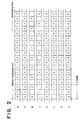
- Fig. 2 presents an example showing an operation at 1/3 normal speed among trick play functions of VTR.
- signal A denotes output of the intra-frame expansion process circuit 1 in Fig. 1, which proceeds from left to right on time base.
- the numbers in the signal A show field numbers of video signals recorded in the magnetic tape, and one box corresponds to a period of one field.
- signals for one frame are always included in one frame period. Since the operation is performed at 1/3 normal speed, data for one frame is output repeatedly and continuously for a period of three frames.
- this signal A is outputted on the screen, so that a sequential field array is reversed at some points in every three-frame period. For example, in Fig. 2, this occurs where signals of a field 1 are followed by signals of a field 0.
- the first change-over circuit 60 divides the output signals of A of the intra-frame expansion process circuit 1 into even fields and odd fields, which are signals B and C.
- the field signals of F are denoted by b where the fields are even fields, and by c where the fields are odd fields.
- the first change-over circuit 60 outputs an even field signal B when the field signal F is b and an odd field signal C when the field signal F is c.
- the field memories 70, 71 have the same addresses for writing and reading data, and the write/read addresses for one field have only to be repeated.
- the first change-over circuit 60 operates as if it gives write enable/write inhibit control signals to the field memories 70, 71. More specifically, when a field signal F is b, the field memory 70 is write enabled, while the field memory 71 is write inhibited. Conversely, when a field signal F is c, the field memory 70 is write inhibited, while the field memory 71 is write enabled. Therefore, the field memory 70 receives signal B which is judged to be even fields by the first change-over circuit 60.
- Signals X are always even field signals as shown in Fig. 2.
- the field memory 71 receives signal C judged to be odd fields by the first change-over circuit 60, and during an odd field period, writes a signal C in the memory and outputs the signal C at the same time, but during an even field period, the field memory 71 is write inhibited, and therefore, again outputs the signal C which has been stored therein. Accordingly, if output of the field memory 71 is denoted as signal Y, field signals of signal Y are always odd field signals.
- the second change-over circuit 61 selects either one of a signal X and a signal Y and outputs a signal Z to be displayed on the screen, and for this selection, uses a control signal S provided by the field detecting circuit 8.
- Fig. 2 shows that a control signal S is x for selection of a signal X and y for selection of a signal Y.
- Control signal S is provided by the field detecting circuit 8.
- the field detecting circuit 8 causes a reciprocal of a multiplication index of reproducing speed to be selected as a number of continuous reproduction of the same field by the second change-over circuit. Since the reproducing speed is 1/3 of normal speed, a reciprocal 3 is found, and signals of each field are reproduced at intervals of three fields.
- Fig. 2 shows the signals of signal Z consisting of field arrays of signal to be reproduced on the screen. Unlike the signal A, in the signal F, there are no field arrays, which are outputted in a backward sequence in time with respect to the input signals in recording, so that a remarkable advantage of this technique is that the displayed pictures are free of flicker in slow play mode.
- the reproducing operation at -1/3 of normal reproducing speed in this embodiment will be described with reference to a timing chart showing the field arrays of signal at various components.
- the signals of the output signal A of the intra-frame expansion process circuit 4 when the reproducing speed is -1/3 of normal speed are the same as in the above-mentioned reproduction at 1/3 of normal speed in respects of the way in which fields are arrayed in a frame as one processing unit and the continuous reproduction of one processing unit at an interval of three frames.
- the difference is that since this operation is reproduction in the reverse direction, the order in which the frames are taken by the tape-head system is a descending order of field numbers as shown in the signal A.
- the operation of the signals F and S provided by the field detecting circuit 8 differs from that in Fig. 2.
- the sequence of b and c is reversed when necessary according to the reproducing speed instead of alternately selecting b and c in compliance with the occurrence of even fields and odd fields.
- the sequence of b and c which represent even and odd fields, is reversed at every three frames. This number three is a reciprocal of 1/3 of normal speed (the signal F in Fig .3).
- a field signal selected by the second change-over circuit 61 according to a signal S is a signal Z corresponding to an odd field in two fields of one processing unit. Since this operation is reproduction in reverse direction, if signals are processed in multiple field units, the number of fields of which is greater than in intra-frame processing, it is nothing other than outputting field signals starting with a field signal of the largest field number (i.e. the last field signal of all field signals recorded in video recording).
- the field arrays in the signals B, C, X, and Y are as shown in Fig. 3, so that the field arrays of signal Z, which are outputted on the screen, have a constant inter-field time difference of one field (except for field arrays without time difference) even in slow play in reverse direction, with the result that a fine picture quality is obtained in slow play.
- Fig. 4 is a block diagram of the video signal recording/reproducing apparatus according to a second embodiment of this invention, and this apparatus is a digital VTR which uses a magnetic tape as a recording medium as in the first embodiment described above and performs video recording and reproduction by compression and expansion processes in intra-frame processing.
- a intra-frame compression process circuit 1 a recording head 2, a reproducing head 3, a intra-frame expansion process circuit 4, and a tape transportation control circuit 5 have the same functions and operates in the same way as in the first embodiment, only difference lying in a change-over circuit 62 and a field memory 72.
- the second embodiment of this invention will be described in the following.
- Fig. 5 is a timing chart showing the field arrays of signal at various components of a reproducing system operated at 1/3 of normal speed as in the first embodiment when the video signal recording/reproducing apparatus according to the second embodiment is used.
- Signal A shows output signals of the intra-frame expansion process circuit 4, which signals are composed of repetitions of three consecutive frames of the same kind, each frame being one processing unit.
- the change-over circuit 62 is controlled by a field signal F, and transfers signals of signal A mentioned above as signal D to the field memory 72 at the subsequent stage only when a field signal F is an even field. Signals D output by the change-over circuit 62 are shown in Fig. 5. Only when a field signal F is an even field, the change-over circuit 62 outputs a signal D, so that even field signals of signal F are shown in Fig. 5.
- the field memory 72 performs a read-after-write function as in the field memories 70, 71 in the first embodiment described above, and has the change-over circuit 62 operate to issue write enable/write inhibit control signals to the field memory 72.
- the field memory 72 In a period when the field memory F is d and the change-over circuit 62 outputs a signal D, the field memory 72 is write enabled. In a period when a signal D is not output, the field memory is write inhibited. Therefore, when a signal D is applied to the field memory 72, the field memory 72 has the signal D written therein and outputs the signal D at the same time.
- the field memory 72 again outputs a signal D which has been stored. Output of the field memory 72 are shown as signal D in Fig. 4.
- the signal Z is composed of signals representing even fields, so that there are no fields which are outputted in a backward sequence in time as in the prior art.
- Fig. 6 is a timing chart showing field arrays of signal at various components for explaining the operation in reproduction at -1/3 of normal speed.
- third embodiment only even fields are outputted on the screen as described, there are no forward field arrays in reverse reproduction between any two fields constituting a frame as one processing unit, so that there is no possibility of reverse field arrays being disturbed in the signal Z in Fig. 6.
- the change-over circuit 62 operated by a signal F to receive the signal A mentioned above the signal D gathered by taking even fields only and the signal Z outputted from the field memory 72 are arrayed as shown in Fig. 7.
- the signal Z of Fig. 7 it is understood that there are two kinds of time difference, that is, there are some fields which have no time difference and other fields which have a time difference corresponding to four fields.
- the field arrays with no time difference are of complete still pictures, and therefore, those field arrays are equivalent to the field arrays with only a time difference of four fields, and they do not produce reproduced pictures which give the viewer an uncomfortable feeling.
- Fig. 8 is a timing chart showing the field arrays of signal in the various components in reproduction at speed -2 times as fast as normal speed, which indicates the operation of this embodiment in high-speed search in reverse direction.
- this embodiment since only even fields are reproduced in this embodiment, there is no possibility that the reverse field arrays are disturbed in the signal Z, so that this embodiment will contributes to improving the picture quality in high-speed search.
- the video signal is formed with a fixed time difference for moving pictures, so that the video signal can be reproduced to form moving pictures with fine picture quality.
- the reciprocal setter 80 in the internal composition of the field detecting circuit 8 of Fig. 9 may be arranged to output an integral number most close to a reciprocal which is not an integral number. Then, a number of continuous reproduction of a field signal can be made an integral number easily.
- a reciprocal of a multiplication index of reproducing speed is less than 1. In this case, as described with reference to the second embodiment, all field data recorded in the tape cannot be retrieved.
- the reciprocal setter 80 by arranging the reciprocal setter 80 to always output 1 as a reciprocal of any output signal when the reproducing speed is higher than normal speed, a number of times of reproduction of each field is made one, resulting in the same conventional reproduction operation in frame units. So, it is only necessary to use a method of the second embodiment which outputs only one field from each processing unit in high-speed search. In a case where one processing unit is a plurality of frames, the first embodiment can be applied to reproduce one of the fields of each frame within one processing unit.
- the field memories (70, 71, 72) are provided separately from the intra-frame expansion process circuit 4.
- the intra-frame expansion process circuit 4 processes two fields at the same time, and when the process result is outputted on the screen, signals are outputted in frame units. Therefore, at least one or more field memories are provided. Even if input signals into the field memories 70, 71, 72 are not divided into fields, it is only necessary for data stored in each field memory to be separated into fields.
- the field memories 70, 71, 72 are compatible with the field memory in the intra-frame expansion process circuit 4.
- the operation of the intra-frame expansion process circuit 4 described with reference to the embodiments of this invention is performed in frame units.
- the separated state of fields is achieved by separating data extending over two fields into ordinary field arrays through write and read operations of the field memory with a memory capacity of one or more fields in the intra-frame expansion process circuit 4. Therefore, by matching the operation of the field memories 70, 71, 72 and the change-over circuits 60, 62 according to this invention with the write and read operations in the intra-frame expansion process circuit 4, data to be stored in the field memories 70, 71, 72 can be easily separated into fields.
- input signals need not necessarily be separated into fields, but it is only necessary to have the signals separated into fields when they are outputted and eventually displayed on the screen in such a way that a number of fields continue which corresponds to a reciprocal of the multiplication index of the reproducing speed and a number of fields as one processing unit.
- the second embodiment is much easier. Whatever is the number of fields as one processing unit, in trick plays by continuously outputting only one field out of one processing unit on the screen, the fields can be arrayed in a predetermined form for reproduction both in forward and reverse directions.
Landscapes
- Engineering & Computer Science (AREA)
- Multimedia (AREA)
- Signal Processing (AREA)
- Television Signal Processing For Recording (AREA)
Abstract
Description
- This invention relates to a video signal recording/reproducing apparatus for recording television signals in a recording media by compressing multiple fields of the television signal as a unit which is hereinafter referred to as multiple field unit, and reproducing the recorded television signals in normal play mode, high-speed search mode or slow play mode.
- To form video recording/reproducing apparatuses (e.g. VTRs, video disc players) for recording and reproducing the video signal, the bit rate reduction technology (or high efficiency coding technology) has been used to reduce the data quantity of the original video signal for a long time video recording. An example of the bit rate reduction technology is intra-frame processing. In the intra-frame processing, a two field unit of the video signal is compressed, that is, every frame of video signal. The video signal in a television signal form is an interlaced signal, two fields of which constitutes one frame. By the intra-frame processing, the video signal is compressed to a non-interplaced form. The non-interplaced signal has the line-to-line distance (between scan lines) reduced to one-half of that for the interlaced signal. Therefore, when a still picture is displayed, the correlation between lines is high and the compression is done efficiently. Even when the displayed image is a moving picture, compression can be done with high efficiency by performing motion compensation between two fields. The high efficiency in the compression mentioned above is not unique to the intra-frame processing, but in general, the compression efficiency will be higher when the processing unit of video signals to be processed become larger so long as there is no scene change in the video signal.
- However, in conventional video signal recording/reproducing apparatuses, if compression in multiple field units is applied, expansion in multiple field units is necessary in reproduction. Therefore, there is a problem, as described below, in trick plays, such as slow play and high-speed search.
- With reference to processing in a two field units (hereinafter referred to as intra-frame processing), this problem will be described. Let us first consider a field array which is reproduced and outputted for slow play. When the video signal recording/ reproducing apparatus is performing compression and expansion in two field units, the video signal can be reproduced only in two field units at all times. Consequently, in slow play, the same frame is output repeatedly for a specified number of times corresponding to the reproducing speed at that time. With regard to the order of arrangement of fields for a period in which the same frame is output repeatedly, if the field that occurs ahead in time of the two fields constituting one frame is named as the former field and the field that occurs behind in time as the latter field, the former and latter fields are displayed alternately on the screen in such a way as a former field - a latter field - a former field - a latter field, and so on. For an array of a former field - a latter field, two fields having between them a forward time difference which corresponds to one field and which is the same as when visual images were recorded, are displayed with a time difference placed in forward direction. For an array of a latter field - a former field, two fields having between them a reverse time difference corresponding to one field are displayed with a time difference placed in forward direction. In a picture reproduced in the forward direction, a time difference in the reverse direction causes a flicker and severely deteriorates the picture quality of the moving picture.
- A case of high-speed search will next be described. As for the field array of output video signal, because the operation is a high-speed search, intermittent frames are arranged with a certain number of frames of video signal thinned out according to the reproducing speed. In a high-speed search in the forward direction, the order of arrangement of the fields is not reversed as in a slow play in the forward direction mentioned above. However, though the time difference between two fields constituting one frame as one processing unit corresponds to a period of one field when these fields are recorded the succeeding fields which are reproduced just after on the screen are those which constitute a processing unit after passage of a specified number of frames decided according to the reproducing speed. Therefore, in a high-speed search, there are mixed field arrays having only a time difference corresponding to one field and field arrays having a greater time difference due to the thinning out of frames for high speed search. As has been described, the presence of the arrays having irregular time differences in reproduced pictures is doubtless a big cause to deteriorate the picture quality in a moving picture.
- From the foregoing description, it will be understood that in conventional video signal recording/ reproducing apparatuses, in trick plays, if the time difference between fields within one processing unit differs from the time difference between processing units, and particularly in a slow play at normal speed or less, there are intermingled dissimilar time differences in the forward and reverse directions, substantially deteriorating the smoothness of the motion of the displayed pictures.
- The object of this invention is to provide a video signal recording/reproducing apparatus free from the impairment of the smoothness of the motion in trick plays, which is caused by compression and expansion of video signal in multiple field units in conventional video signal recording/reproducing apparatuses.
- In order to achieve the above object, a video signal recording/reproducing apparatus comprises compression means for compressing the video signal in multiple field units, recording/reproducing means for recording the compressed video signal in a recording medium and reproducing the recorded signal, expansion means for expanding the reproduced signal in multiple field units mentioned above, reproducing mode setting means for setting a desired reproducing speed, recording medium transportation control means for controlling the transportation speed of the recording medium to suit said desired reproducing speed, synchronization detecting means for obtaining a field signal by detecting a synchronization pattern from said reproduced signal, field detecting means for obtaining a reciprocal of a reproducing speed multiplication factor with respect to normal speed from said reproducing speed and making a field period expressed by said reciprocal a continuous field reproduction period according to said reciprocal and said field signal from said synchronization detecting means, and change-over means for repeatedly outputting on the screen each field of the video signal in multiple field units given by said expansion means for said continuous field period.
- Another video signal recording/reproducing apparatus according to this invention comprises compression means for compressing the video signal in multiple field units, recording/reproducing means for recording the compressed video signal in a recording medium and reproducing the recorded signal, expansion means for expanding the reproduced signal in multiple field units mentioned above, reproducing mode setting means for setting a desired reproducing speed, recording medium transportation control means for controlling the transportation speed of the recording means to suit said reproducing speed, synchronization detecting means for obtaining a field signal by detecting a synchronization pattern from said reproduced signal, and change-over means capable of sequentially outputting the video signal in said multiple field units according to a field signal from said synchronization detecting means in normal reproduction, and also continuously and repeatedly outputting one field of signal out of one unit of the multiple field units until signal of the next unit of the multiple field units can be obtained.
- According to the above-mentioned arrangements of this invention, even if the video signal is compressed and expanded in multiple field units, the video signal having a fixed time difference with regard to the motion of the images in a trick play can be displayed on the screen, so that a good picture quality can be obtained with no inadequacy of the motion of the reproduced pictures.
-
- Fig. 1 is a block diagram of a video signal recording/reproducing apparatus according to a first embodiment of this invention and shows the apparatus processing the video signal in two field units;
- Figs. 2, 3 are timing charts showing field arrays of signal in the constituent elements for explaining the video signal recording/reproducing apparatus according to the first embodiment;
- Fig. 4 is a block diagram of a video signal recording/reproducing apparatus according to a second embodiment of this invention and shows the apparatus performing intra-frame processing;
- Figs. 5, 6, 7, 8 are timing charts showing field arrays of signal in the constituent elements for explaining the video signal recording/reproducing apparatus according to the second embodiment; and
- Fig. 9 is a block diagram showing the internal construction of a
field detecting circuit 8, which is a component of the video signal recording/reproducing apparatus according to the first embodiment. - Fig. 1 is a block diagram of the video signal recording/reproducing apparatus according to the first embodiment of this invention and the apparatus is a digital video tape recorder (VTR) which uses a magnetic tape as a recording medium, records and reproduces the video signal through the compression and expansion processes in which two fields, namely, one frame of video signal is handled as a processing unit. Here, a process treating one frame as a processing unit is referred to as intra-frame processing.
- In Fig. 1,
reference numeral 1 indicates an intra-frame compression process circuit for an intra-frame compression of the input video signal, and 2 indicates a recording head which lays down output signal of the intra-frame compression circuit on amagnetic tape 10 in a magnetization pattern. A video signal recording section is formed by the intra-framecompression process circuit 1 and therecording head 2.Reference numeral 3 indicates a preproducing head for reproducing the signal from themagnetic tape head 3, and by these two components, a video signal reproducing section is formed which reconstitutes the original video signal from the signal recorded in the magnetic tape by the video signal recording section. Needless to say, therecording head 2 and the reproducinghead 3 are rotating heads mounted on a rotating cylinder (not shown) on which the magnetic head is wrapped with a specified angle. The same head may be used as therecording head 2 and the reproducinghead 3. A tapetransportation control circuit 5 has a tape transfer function (not shown) including a capstan motor, a capstan, etc. and controls a tape transportation speed according to a desired reproducing speed in reproduction. Said desired reproducing speed can be set arbitrarily by the user of this video signal recording/reproducing apparatus by the use of a reproducingspeed setter 12. - A
synchronization detector 11 detects a synchronization pattern on themagnetic tape 10 from the signal obtained by the reproducinghead 3, controls a rotating speed of the rotating cylinder (not shown) so that the reproducinghead 3 optimally traces tracks or sinks where the magnetization pattern is recorded (this operation is called tracking), and also detects and outputs a start timing of frames, each being a processing unit in the intra-frameexpansion process circuit 4 and a start timing of fields to display the output of the intra-frameexpansion process circuit 4 in field units on the screen.Reference numeral 60 indicates a first change-over circuit for dividing output signal of the intra-frame expansion process circuit to send individual fields alternately to two separate systems according to field signals detected by thesynchronization detector circuit 11.Reference numeral 70 indicates a first field memory for storing output signal from one side of the change-overcircuit circuit field memories mode setter 12 to be selected as a number of continuous reproduction of one field, thefield selecting circuit 8 outputs a field signal F for controlling the first change-overcircuit 60 and a control signal S for controlling the second change-overcircuit 61. - Fig. 9 is a block diagram of an example of the internal construction of the
field detecting circuit 8. Areciprocal setter 80 outputs a forward/reverse signal for specifying the forward or reverse direction according to codes representing a reciprocal of an absolute value of a reproducing speed and the reproducing speed supplied by the reproducingmode setter 12. This reciprocal setter can be realized by use of a Read-Only-Memory (ROM). By setting one of output signals of thereciprocal setter 80 as a preset value, acounter 81 performs a countdown by using a field signal from thesynchronization detector 11 as a counter clock signal, sends an underflow pulse as an output signal, and receives the underflow pulse as a load signal to the counter itself. (The preset value is used as an initial value of the countdown.) A first flip-flop 82 receives an underflow pulse provided by thecounter 81 as an input clock signal and gets the inverted output as input data for the first flip-flop itself. A second flip-flop 83 receives the inverted output of the first flip-flop 82 as a clock signal and gets the inverted output of the second flip-flop as input data for the second flip-flop itself. Aswitch 84 operates according to a forward/reverse signal from thereciprocal setter 80. When a forward/reverse signal denotes the forward direction, in compliance with the inverted output of the first flip-flop, theswitch 84 sets a control signal S which is provided by thefield detecting circuit 8, and when a forward/reverse signal denotes the reverse direction, in compliance with the inverted output from the second flip-flop, theswitch 84 sets a control signal S which is provided by thefield detecting circuit 8. Afield signal setter 85 operates according to a forward/reverse signal from thereciprocal setter 80. When a forward/reverse signal denotes the forward direction, thefield signal setter 85 keeps a field signal from thesynchronization detecting circuit 11 its current state and outputs a field signal F. When a forward/reverse signal denotes the reverse direction, thefield signal setter 85 operates according to two kinds of state of output signals of the flip-flop 83. When the output signal is in one of the two states, thefield signal setter 85 keeps the current state of field signal from thesynchronization detector 11, and outputs a field signal F, and when the output signal is in the other of the two states, thefield signal setter 85 inverts a field signal from thesynchronization detector 11 and outputs an inverted field signal F. This field signal setter can be realized easily by a ROM, but can be realized very easily by using a logic circuit or a switch. - The operation of the above-mentioned arrangement of the present embodiment will be described with reference to a timing chart showing field arrays of signal at various component of the present embodiment in Fig. 2. Fig. 2 presents an example showing an operation at 1/3 normal speed among trick play functions of VTR. In Fig. 2, signal A denotes output of the intra-frame
expansion process circuit 1 in Fig. 1, which proceeds from left to right on time base. The numbers in the signal A show field numbers of video signals recorded in the magnetic tape, and one box corresponds to a period of one field. In this embodiment in which intra-frame processing is performed, in the signal A, signals for one frame are always included in one frame period. Since the operation is performed at 1/3 normal speed, data for one frame is output repeatedly and continuously for a period of three frames. - Conventionally, this signal A is outputted on the screen, so that a sequential field array is reversed at some points in every three-frame period. For example, in Fig. 2, this occurs where signals of a
field 1 are followed by signals of afield 0. - In this embodiment, by field signals of F from the
field detecting circuit 8, the first change-over circuit 60 divides the output signals of A of the intra-frameexpansion process circuit 1 into even fields and odd fields, which are signals B and C. In Fig. 2, the field signals of F are denoted by b where the fields are even fields, and by c where the fields are odd fields. In other words, the first change-over circuit 60 outputs an even field signal B when the field signal F is b and an odd field signal C when the field signal F is c. Description will now be made of the first change-over circuit 60, and thefield memories field memories over circuit 60 is written and read, that is to say, the so-called read-after-write operation is performed. The first change-over circuit 60 operates as if it gives write enable/write inhibit control signals to thefield memories field memory 70 is write enabled, while thefield memory 71 is write inhibited. Conversely, when a field signal F is c, thefield memory 70 is write inhibited, while thefield memory 71 is write enabled. Therefore, thefield memory 70 receives signal B which is judged to be even fields by the first change-over circuit 60. During an even field period, a signal B is written in the memory and at the same time, the signal B is output. On the contrary, during an odd field period, thefield memory 70 is write inhibited, so that the signal B stored in thefield memory 70 is outputted again. This signal outputted from thefield memory 70 is referred to as a signal X. Signals X are always even field signals as shown in Fig. 2. - On the other hand, the
field memory 71 receives signal C judged to be odd fields by the first change-over circuit 60, and during an odd field period, writes a signal C in the memory and outputs the signal C at the same time, but during an even field period, thefield memory 71 is write inhibited, and therefore, again outputs the signal C which has been stored therein. Accordingly, if output of thefield memory 71 is denoted as signal Y, field signals of signal Y are always odd field signals. - The second change-
over circuit 61 selects either one of a signal X and a signal Y and outputs a signal Z to be displayed on the screen, and for this selection, uses a control signal S provided by thefield detecting circuit 8. Fig. 2 shows that a control signal S is x for selection of a signal X and y for selection of a signal Y. Control signal S is provided by thefield detecting circuit 8. Thefield detecting circuit 8 causes a reciprocal of a multiplication index of reproducing speed to be selected as a number of continuous reproduction of the same field by the second change-over circuit. Since the reproducing speed is 1/3 of normal speed, a reciprocal 3 is found, and signals of each field are reproduced at intervals of three fields. - Fig. 2 shows the signals of signal Z consisting of field arrays of signal to be reproduced on the screen. Unlike the signal A, in the signal F, there are no field arrays, which are outputted in a backward sequence in time with respect to the input signals in recording, so that a remarkable advantage of this technique is that the displayed pictures are free of flicker in slow play mode.
- The reproducing operation at -1/3 of normal reproducing speed in this embodiment will be described with reference to a timing chart showing the field arrays of signal at various components. The signals of the output signal A of the intra-frame
expansion process circuit 4 when the reproducing speed is -1/3 of normal speed are the same as in the above-mentioned reproduction at 1/3 of normal speed in respects of the way in which fields are arrayed in a frame as one processing unit and the continuous reproduction of one processing unit at an interval of three frames. The difference is that since this operation is reproduction in the reverse direction, the order in which the frames are taken by the tape-head system is a descending order of field numbers as shown in the signal A. In the prior art, even though this operation is reproduction in reverse direction, there are field arrays in one of which there is a time difference of three fields, including one field in forward direction and one field in reverse direction. (e.g. fromfield 5 tofield 4, fromfield 5 to field 2) - In this embodiment, in a reverse reproduction, the operation of the signals F and S provided by the
field detecting circuit 8 differs from that in Fig. 2. First with regard to the signal F, as has been described of the internal construction of thefield detecting circuit 8, the sequence of b and c is reversed when necessary according to the reproducing speed instead of alternately selecting b and c in compliance with the occurrence of even fields and odd fields. In the reproduction at -1/3 of normal speed, the sequence of b and c, which represent even and odd fields, is reversed at every three frames. This number three is a reciprocal of 1/3 of normal speed (the signal F in Fig .3). With regard to the signal S, as with the signal F, the selection of output of thefield memory 70 and the field memory 71 (signal X and signal Y) is reversed every three frames. A field signal selected by the second change-over circuit 61 according to a signal S is a signal Z corresponding to an odd field in two fields of one processing unit. Since this operation is reproduction in reverse direction, if signals are processed in multiple field units, the number of fields of which is greater than in intra-frame processing, it is nothing other than outputting field signals starting with a field signal of the largest field number (i.e. the last field signal of all field signals recorded in video recording). - According to the signals F and S provided by the
field detecting circuit 8 described above, the field arrays in the signals B, C, X, and Y are as shown in Fig. 3, so that the field arrays of signal Z, which are outputted on the screen, have a constant inter-field time difference of one field (except for field arrays without time difference) even in slow play in reverse direction, with the result that a fine picture quality is obtained in slow play. - Fig. 4 is a block diagram of the video signal recording/reproducing apparatus according to a second embodiment of this invention, and this apparatus is a digital VTR which uses a magnetic tape as a recording medium as in the first embodiment described above and performs video recording and reproduction by compression and expansion processes in intra-frame processing. In Fig. 4, a intra-frame
compression process circuit 1, arecording head 2, a reproducinghead 3, a intra-frameexpansion process circuit 4, and a tapetransportation control circuit 5 have the same functions and operates in the same way as in the first embodiment, only difference lying in a change-over circuit 62 and afield memory 72. The second embodiment of this invention will be described in the following. - Fig. 5 is a timing chart showing the field arrays of signal at various components of a reproducing system operated at 1/3 of normal speed as in the first embodiment when the video signal recording/reproducing apparatus according to the second embodiment is used. Signal A shows output signals of the intra-frame
expansion process circuit 4, which signals are composed of repetitions of three consecutive frames of the same kind, each frame being one processing unit. The change-over circuit 62 is controlled by a field signal F, and transfers signals of signal A mentioned above as signal D to thefield memory 72 at the subsequent stage only when a field signal F is an even field. Signals D output by the change-over circuit 62 are shown in Fig. 5. Only when a field signal F is an even field, the change-over circuit 62 outputs a signal D, so that even field signals of signal F are shown in Fig. 5. - The
field memory 72 performs a read-after-write function as in thefield memories over circuit 62 operate to issue write enable/write inhibit control signals to thefield memory 72. In a period when the field memory F is d and the change-over circuit 62 outputs a signal D, thefield memory 72 is write enabled. In a period when a signal D is not output, the field memory is write inhibited. Therefore, when a signal D is applied to thefield memory 72, thefield memory 72 has the signal D written therein and outputs the signal D at the same time. When a field signal F is an odd signal and a signal D is not output, thefield memory 72 again outputs a signal D which has been stored. Output of thefield memory 72 are shown as signal D in Fig. 4. In contrast to the first embodiment, the signal Z is composed of signals representing even fields, so that there are no fields which are outputted in a backward sequence in time as in the prior art. - Description will then be made of a slow play in reverse direction. Fig. 6 is a timing chart showing field arrays of signal at various components for explaining the operation in reproduction at -1/3 of normal speed. In third embodiment only even fields are outputted on the screen as described, there are no forward field arrays in reverse reproduction between any two fields constituting a frame as one processing unit, so that there is no possibility of reverse field arrays being disturbed in the signal Z in Fig. 6.
- The operation of reproduction at speed twice faster than normal speed in this second embodiment will be described with reference to a timing chart of Fig. 7 showing field arrays of signal in the various components. For the output signal A of the intra-frame
expansion process circuit 4 in reproduction at twice faster speed, unlike in reproduction at 1/3 of normal speed, data of all frames (data of all fields) cannot be obtained from the tape-head system but only data of every other frame can be obtained. Therefore, the numbers of signal A are arrayed as shown in Fig. 7. - In a system in which intra-frame processing is performed as in this embodiment, even in high-speed search faster than normal speed, an expansion process is carried out in frame units, so that the fields are arrayed in frame units for the signal A. Accordingly, if signal A is reproduced on the screen as it is like in the prior art, there are bound to be field arrays which have dissimilar time differences between fields. Referring to Fig. 7, signals are reproduced in frame units starting with the leftmost frame, and a time difference corresponding to one field is placed between
field 0 andfield 1 in reproduction. However, betweenfield 1 andfield 4, there is a time difference corresponding to three fields. To put differently, in the reproduced pictures on the screen, a time difference of one field and a time difference of three fields occur alternately. This phenomenon does not become a problem when only video signals of still pictures are recorded. In video recording/reproducing apparatuses for recording video signals of moving pictures, such as a VTR, the irregularity of time difference between fields will result in producing pictures giving the viewer an uncomfortable sensation. - In this second embodiment, by the use of the change-
over circuit 62 operated by a signal F to receive the signal A mentioned above, the signal D gathered by taking even fields only and the signal Z outputted from thefield memory 72 are arrayed as shown in Fig. 7. By looking at the signal Z of Fig. 7, it is understood that there are two kinds of time difference, that is, there are some fields which have no time difference and other fields which have a time difference corresponding to four fields. The field arrays with no time difference are of complete still pictures, and therefore, those field arrays are equivalent to the field arrays with only a time difference of four fields, and they do not produce reproduced pictures which give the viewer an uncomfortable feeling. - Fig. 8 is a timing chart showing the field arrays of signal in the various components in reproduction at speed -2 times as fast as normal speed, which indicates the operation of this embodiment in high-speed search in reverse direction. In this case, too, since only even fields are reproduced in this embodiment, there is no possibility that the reverse field arrays are disturbed in the signal Z, so that this embodiment will contributes to improving the picture quality in high-speed search.
- As described above, by the arrangement of this embodiment, only time difference between processing units is shown in reproduced pictures even in high-speed search. The video signal is formed with a fixed time difference for moving pictures, so that the video signal can be reproduced to form moving pictures with fine picture quality.
- If a reciprocal of a reproducing speed multiplication factor is not an integral number, the
reciprocal setter 80 in the internal composition of thefield detecting circuit 8 of Fig. 9 may be arranged to output an integral number most close to a reciprocal which is not an integral number. Then, a number of continuous reproduction of a field signal can be made an integral number easily. In a high-speed search at higher speed than normal speed, a reciprocal of a multiplication index of reproducing speed is less than 1. In this case, as described with reference to the second embodiment, all field data recorded in the tape cannot be retrieved. Therefore, by arranging thereciprocal setter 80 to alwaysoutput 1 as a reciprocal of any output signal when the reproducing speed is higher than normal speed, a number of times of reproduction of each field is made one, resulting in the same conventional reproduction operation in frame units. So, it is only necessary to use a method of the second embodiment which outputs only one field from each processing unit in high-speed search. In a case where one processing unit is a plurality of frames, the first embodiment can be applied to reproduce one of the fields of each frame within one processing unit. - In the arrangements of the first and second embodiment (Figs. 1, 4), the field memories (70, 71, 72) are provided separately from the intra-frame
expansion process circuit 4. However, the intra-frameexpansion process circuit 4 processes two fields at the same time, and when the process result is outputted on the screen, signals are outputted in frame units. Therefore, at least one or more field memories are provided. Even if input signals into thefield memories field memories expansion process circuit 4. The operation of the intra-frameexpansion process circuit 4 described with reference to the embodiments of this invention is performed in frame units. However, two fields constituting one frame of the output signal A have been separated before they are output. The separated state of fields is achieved by separating data extending over two fields into ordinary field arrays through write and read operations of the field memory with a memory capacity of one or more fields in the intra-frameexpansion process circuit 4. Therefore, by matching the operation of thefield memories circuits expansion process circuit 4, data to be stored in thefield memories
Claims (2)
- A video signal recording/reproducing apparatus comprising:
compression process means (1) for compressing the video signal in multiple field units;
recording/reproducing means (2, 3) for recording the compressed signal in a recording medium and reproducing the recorded signal;
expansion means (4) for expanding said reproduced signal in multiple field units;
reproducing mode setting means (12) for setting a desired reproducing speed;
recording medium transportation control means (5) for controlling a transportation speed of said recording medium according to said reproducing speed;
synchronization detecting means (11) for obtaining a field signal by detecting a synchronization pattern from said reproduced signal;
field detecting means (8) for finding a reciprocal of a reproducing speed multiplication factor with respect to normal speed and making a field period expressed by said reciprocal a continuous field period according to said reciprocal and a field signal obtained by said synchronization detecting means; and
change-over means (60, 61) for continuously and repeatedly outputting on the screen individual fields of the video signal in multiple field units obtained by said expansion means for said continuous field period. - A video signal recording/reproducing apparatus comprising:
compression process means (1) for compressing the video signal in multiple field units;
recording/reproducing means (2, 3) for recording the compressed signal in a recording medium and reproducing the recorded signal;
expansion means (4) for expanding the reproduced signal in said multiple field units;
reproducing mode setting means (12) for setting a desired reproducing speed;
recording medium transportation control means (5) for controlling a transportation speed of said recording medium according to said reproducing speed;
synchronization detecting means (11) for obtaining a field signal by detecting a synchronization pattern from said reproduced signal; and
change-over means (62) for capable of sequentially outputting signals in said multiple field units according to a field signal from said synchronization detecting means in normal reproduction, and also continuously and repeatedly outputting one field of signals out of one unit of said multiple field units until signals of the next unit of said multiple field units can be obtained.
Applications Claiming Priority (2)
| Application Number | Priority Date | Filing Date | Title |
|---|---|---|---|
| JP113305/90 | 1990-04-27 | ||
| JP2113305A JPH0410880A (en) | 1990-04-27 | 1990-04-27 | Method for recording and reproducing video signal |
Publications (3)
| Publication Number | Publication Date |
|---|---|
| EP0454460A2 true EP0454460A2 (en) | 1991-10-30 |
| EP0454460A3 EP0454460A3 (en) | 1992-09-02 |
| EP0454460B1 EP0454460B1 (en) | 1997-01-22 |
Family
ID=14608865
Family Applications (1)
| Application Number | Title | Priority Date | Filing Date |
|---|---|---|---|
| EP91303731A Expired - Lifetime EP0454460B1 (en) | 1990-04-27 | 1991-04-25 | Video signal recording/reproducing apparatus |
Country Status (7)
| Country | Link |
|---|---|
| US (1) | US5126852A (en) |
| EP (1) | EP0454460B1 (en) |
| JP (1) | JPH0410880A (en) |
| KR (1) | KR940011109B1 (en) |
| AU (1) | AU623302B2 (en) |
| CA (1) | CA2048926C (en) |
| DE (1) | DE69124283T2 (en) |
Cited By (11)
| Publication number | Priority date | Publication date | Assignee | Title |
|---|---|---|---|---|
| EP0500358A2 (en) * | 1991-02-19 | 1992-08-26 | Matsushita Electric Industrial Co., Ltd. | Signal processing method of digital VTR |
| GB2264838A (en) * | 1992-02-21 | 1993-09-08 | Samsung Electronics Co Ltd | Video recording apparatus |
| WO1994018793A1 (en) * | 1993-02-08 | 1994-08-18 | Deutsche Thomson-Brandt Gmbh | Time-compressed signal recording and reproducing process |
| EP0629087A2 (en) * | 1993-06-08 | 1994-12-14 | Sony Corporation | Recording/reproducing apparatus and reproducing apparatus |
| EP0660606A1 (en) * | 1993-07-09 | 1995-06-28 | Sony Corporation | Method and device for decoding picture signal |
| US5510899A (en) * | 1993-04-02 | 1996-04-23 | Goldstar Co., Ltd. | Method of multi-speed recording-reproducing a video signal in digital video cassette recorder |
| EP0706294A3 (en) * | 1994-10-05 | 1997-12-17 | Sony Corporation | Video signal processing apparatus and method |
| EP0853432A2 (en) * | 1992-12-22 | 1998-07-15 | Canon Kabushiki Kaisha | An image signal reproducing apparatus |
| US5812735A (en) * | 1993-07-09 | 1998-09-22 | Sony Corporaiton | Picture signal decoding method and picture signal decoding apparatus |
| WO1999057724A1 (en) * | 1998-05-06 | 1999-11-11 | Thomson Licensing S.A. | Bit stream processing for replay |
| EP1393557A1 (en) * | 2001-04-24 | 2004-03-03 | Koninklijke Philips Electronics N.V. | Method and device for generating a video signal |
Families Citing this family (51)
| Publication number | Priority date | Publication date | Assignee | Title |
|---|---|---|---|---|
| JP3161614B2 (en) * | 1991-11-30 | 2001-04-25 | ソニー株式会社 | Video decoding device |
| JP3205580B2 (en) * | 1991-12-18 | 2001-09-04 | パイオニア株式会社 | Video signal playback device |
| KR100206262B1 (en) * | 1992-02-29 | 1999-07-01 | 윤종용 | Replay screen seek control device of digital vtr |
| US5623344A (en) * | 1992-09-01 | 1997-04-22 | Hitachi America, Ltd. | Digital video recording device with trick play capability |
| US5583650A (en) * | 1992-09-01 | 1996-12-10 | Hitachi America, Ltd. | Digital recording and playback device error correction methods and apparatus for use with trick play data |
| JP2785220B2 (en) * | 1992-09-22 | 1998-08-13 | ソニー株式会社 | Data encoding device and method, and data decoding device and method |
| JP3240017B2 (en) * | 1993-01-11 | 2001-12-17 | ソニー株式会社 | MPEG signal recording method and MPEG signal reproducing method |
| US5805762A (en) * | 1993-01-13 | 1998-09-08 | Hitachi America, Ltd. | Video recording device compatible transmitter |
| US5887115A (en) * | 1993-01-13 | 1999-03-23 | Hitachi America, Ltd. | Method and apparatus for implementing a video tape recorder for recording digital video signals having either a fixed or variable data transmission rate |
| US5717816A (en) * | 1993-01-13 | 1998-02-10 | Hitachi America Ltd. | Method and apparatus for the selection of data for use in VTR trick playback operation in a system using intra-coded video frames |
| US5778143A (en) * | 1993-01-13 | 1998-07-07 | Hitachi America, Ltd. | Method and apparatus for the selection of data for use in VTR trick playback operation in a system using progressive picture refresh |
| US5377051A (en) * | 1993-01-13 | 1994-12-27 | Hitachi America, Ltd. | Digital video recorder compatible receiver with trick play image enhancement |
| US5726711A (en) * | 1993-01-13 | 1998-03-10 | Hitachi America, Ltd. | Intra-coded video frame data processing methods and apparatus |
| US5444575A (en) * | 1994-01-21 | 1995-08-22 | Hitachi America, Ltd. | Method for recording digital data using a set of heads including a pair of co-located heads to record data at a rate lower than the full recording rate possible using the set of heads |
| US5673358A (en) * | 1993-01-13 | 1997-09-30 | Hitachi America, Ltd. | Method for generating a reduced rate digital bitstream by selecting data as a function of the position within an image to which the data corresponds |
| US5933567A (en) * | 1993-01-13 | 1999-08-03 | Hitachi America, Ltd. | Method and apparatus for controlling the position of the heads of a digital video tape recorder during trick play operation and for recording digital data on a tape |
| US5576902A (en) * | 1993-01-13 | 1996-11-19 | Hitachi America, Ltd. | Method and apparatus directed to processing trick play video data to compensate for intentionally omitted data |
| US5614952A (en) * | 1994-10-11 | 1997-03-25 | Hitachi America, Ltd. | Digital video decoder for decoding digital high definition and/or digital standard definition television signals |
| US5786858A (en) * | 1993-01-19 | 1998-07-28 | Sony Corporation | Method of encoding image signal, apparatus for encoding image signal, method of decoding image signal, apparatus for decoding image signal, and image signal recording medium |
| US5802505A (en) * | 1993-04-13 | 1998-09-01 | Matsushita Electric Industrial Co., Ltd. | Waveform signal equalizing method and apparatus and signal recording and reproducing apparatus |
| KR970005641B1 (en) | 1993-04-16 | 1997-04-18 | 구자홍 | Recording and reproducing control circuit of digital vcr |
| EP0631441B1 (en) * | 1993-06-22 | 2000-02-09 | Canon Kabushiki Kaisha | Image processing apparatus |
| US5828786A (en) * | 1993-12-02 | 1998-10-27 | General Instrument Corporation | Analyzer and methods for detecting and processing video data types in a video data stream |
| JP3385109B2 (en) * | 1994-04-12 | 2003-03-10 | 三菱電機株式会社 | Digital VTR |
| US6977964B1 (en) * | 1994-04-12 | 2005-12-20 | Mitsubishi Denki Kabushiki Kaisha | Digital VTR for recording and replaying data depending on replay modes |
| KR100384572B1 (en) * | 1994-04-13 | 2003-08-21 | 알씨에이 라이센싱 코오포레이숀 | digital VCR with non-standard speed playback |
| JP3330459B2 (en) * | 1994-07-04 | 2002-09-30 | 三菱電機株式会社 | Magnetic recording / reproducing device |
| US5592299A (en) * | 1994-09-26 | 1997-01-07 | Hitachi America, Ltd. | Method and apparatus for reducing the amount of data required to represent a video frame |
| KR100251456B1 (en) * | 1997-11-04 | 2000-04-15 | 윤종용 | Screen device for low speed reproducing a moving picture |
| US7272298B1 (en) | 1998-05-06 | 2007-09-18 | Burst.Com, Inc. | System and method for time-shifted program viewing |
| US6385248B1 (en) | 1998-05-12 | 2002-05-07 | Hitachi America Ltd. | Methods and apparatus for processing luminance and chrominance image data |
| US6148032A (en) * | 1998-05-12 | 2000-11-14 | Hitachi America, Ltd. | Methods and apparatus for reducing the cost of video decoders |
| US6122321A (en) * | 1998-05-12 | 2000-09-19 | Hitachi America, Ltd. | Methods and apparatus for reducing the complexity of inverse quantization operations |
| US7558472B2 (en) | 2000-08-22 | 2009-07-07 | Tivo Inc. | Multimedia signal processing system |
| US8577205B2 (en) | 1998-07-30 | 2013-11-05 | Tivo Inc. | Digital video recording system |
| US8380041B2 (en) | 1998-07-30 | 2013-02-19 | Tivo Inc. | Transportable digital video recorder system |
| US6233389B1 (en) | 1998-07-30 | 2001-05-15 | Tivo, Inc. | Multimedia time warping system |
| US7895633B2 (en) | 2004-11-19 | 2011-02-22 | Tivo Inc. | Method and apparatus for secure transfer and playback of multimedia content |
| US8165451B2 (en) | 2007-11-20 | 2012-04-24 | Echostar Technologies L.L.C. | Methods and apparatus for displaying information regarding interstitials of a video stream |
| US8136140B2 (en) | 2007-11-20 | 2012-03-13 | Dish Network L.L.C. | Methods and apparatus for generating metadata utilized to filter content from a video stream using text data |
| US8165450B2 (en) | 2007-11-19 | 2012-04-24 | Echostar Technologies L.L.C. | Methods and apparatus for filtering content in a video stream using text data |
| US8606085B2 (en) | 2008-03-20 | 2013-12-10 | Dish Network L.L.C. | Method and apparatus for replacement of audio data in recorded audio/video stream |
| US8156520B2 (en) * | 2008-05-30 | 2012-04-10 | EchoStar Technologies, L.L.C. | Methods and apparatus for presenting substitute content in an audio/video stream using text data |
| US20090307741A1 (en) * | 2008-06-09 | 2009-12-10 | Echostar Technologies L.L.C. | Methods and apparatus for dividing an audio/video stream into multiple segments using text data |
| US8407735B2 (en) | 2008-12-24 | 2013-03-26 | Echostar Technologies L.L.C. | Methods and apparatus for identifying segments of content in a presentation stream using signature data |
| US8510771B2 (en) | 2008-12-24 | 2013-08-13 | Echostar Technologies L.L.C. | Methods and apparatus for filtering content from a presentation stream using signature data |
| US8588579B2 (en) | 2008-12-24 | 2013-11-19 | Echostar Technologies L.L.C. | Methods and apparatus for filtering and inserting content into a presentation stream using signature data |
| US8437617B2 (en) | 2009-06-17 | 2013-05-07 | Echostar Technologies L.L.C. | Method and apparatus for modifying the presentation of content |
| US20110197224A1 (en) * | 2010-02-09 | 2011-08-11 | Echostar Global B.V. | Methods and Apparatus For Selecting Advertisements For Output By A Television Receiver Based on Social Network Profile Data |
| US8934758B2 (en) | 2010-02-09 | 2015-01-13 | Echostar Global B.V. | Methods and apparatus for presenting supplemental content in association with recorded content |
| US11172269B2 (en) | 2020-03-04 | 2021-11-09 | Dish Network L.L.C. | Automated commercial content shifting in a video streaming system |
Citations (6)
| Publication number | Priority date | Publication date | Assignee | Title |
|---|---|---|---|---|
| DE2646899A1 (en) * | 1976-10-18 | 1978-04-20 | Bosch Gmbh Robert | Reproduction of video signals on magnetic tape - is carried out at different speed, with reproduced video signal subjected to standard change |
| WO1982000558A1 (en) * | 1980-07-28 | 1982-02-18 | Physics Inc Spin | Slow motion effect using longitudinal recording and forward/reverse tape transportation |
| US4849812A (en) * | 1987-03-10 | 1989-07-18 | U.S. Philips Corporation | Television system in which digitized picture signals subjected to a transform coding are transmitted from an encoding station to a decoding station |
| US4864430A (en) * | 1986-06-23 | 1989-09-05 | Canon Kabushiki Kaisha | Video signal reproducing apparatus with memory and capability for reproducing at diverse reproduction speeds |
| US4890165A (en) * | 1987-04-06 | 1989-12-26 | Canon Kabushiki Kaisha | Image pick-up apparatus for producing video signals of high information density in time base direction |
| EP0350902A2 (en) * | 1988-07-12 | 1990-01-17 | Sharp Kabushiki Kaisha | Video signal recording and reproducing device |
Family Cites Families (5)
| Publication number | Priority date | Publication date | Assignee | Title |
|---|---|---|---|---|
| JPS5614787A (en) * | 1979-07-18 | 1981-02-13 | Sony Corp | Video signal reproduction system |
| JPS56158581A (en) * | 1980-05-10 | 1981-12-07 | Victor Co Of Japan Ltd | Recording and playback system for rotating recording medium |
| DE3543540A1 (en) * | 1985-12-10 | 1987-06-11 | Bosch Gmbh Robert | METHOD FOR PLAYING BACK VIDEO SIGNALS STORED ON MAGNETIC TAPE WITH A TAPE SPEED DIFFERENT FROM THE TAPE SPEED AND THE CIRCUIT ARRANGEMENT THEREFOR |
| KR900007470B1 (en) * | 1986-02-18 | 1990-10-10 | 마쯔시다덴기산교 가부시기가이샤 | The method of recording video signal and apparatus for video signal |
| JPH01314080A (en) * | 1988-06-13 | 1989-12-19 | Hitachi Ltd | Picture data transfer system |
-
1990
- 1990-04-27 JP JP2113305A patent/JPH0410880A/en active Pending
-
1991
- 1991-04-17 US US07/686,483 patent/US5126852A/en not_active Expired - Lifetime
- 1991-04-19 AU AU75114/91A patent/AU623302B2/en not_active Ceased
- 1991-04-22 CA CA002048926A patent/CA2048926C/en not_active Expired - Fee Related
- 1991-04-25 DE DE69124283T patent/DE69124283T2/en not_active Expired - Fee Related
- 1991-04-25 EP EP91303731A patent/EP0454460B1/en not_active Expired - Lifetime
- 1991-04-27 KR KR1019910006819A patent/KR940011109B1/en not_active IP Right Cessation
Patent Citations (6)
| Publication number | Priority date | Publication date | Assignee | Title |
|---|---|---|---|---|
| DE2646899A1 (en) * | 1976-10-18 | 1978-04-20 | Bosch Gmbh Robert | Reproduction of video signals on magnetic tape - is carried out at different speed, with reproduced video signal subjected to standard change |
| WO1982000558A1 (en) * | 1980-07-28 | 1982-02-18 | Physics Inc Spin | Slow motion effect using longitudinal recording and forward/reverse tape transportation |
| US4864430A (en) * | 1986-06-23 | 1989-09-05 | Canon Kabushiki Kaisha | Video signal reproducing apparatus with memory and capability for reproducing at diverse reproduction speeds |
| US4849812A (en) * | 1987-03-10 | 1989-07-18 | U.S. Philips Corporation | Television system in which digitized picture signals subjected to a transform coding are transmitted from an encoding station to a decoding station |
| US4890165A (en) * | 1987-04-06 | 1989-12-26 | Canon Kabushiki Kaisha | Image pick-up apparatus for producing video signals of high information density in time base direction |
| EP0350902A2 (en) * | 1988-07-12 | 1990-01-17 | Sharp Kabushiki Kaisha | Video signal recording and reproducing device |
Cited By (19)
| Publication number | Priority date | Publication date | Assignee | Title |
|---|---|---|---|---|
| EP0500358A3 (en) * | 1991-02-19 | 1993-11-24 | Matsushita Electric Ind Co Ltd | Signal processing method of digital vtr |
| EP0500358A2 (en) * | 1991-02-19 | 1992-08-26 | Matsushita Electric Industrial Co., Ltd. | Signal processing method of digital VTR |
| GB2264838A (en) * | 1992-02-21 | 1993-09-08 | Samsung Electronics Co Ltd | Video recording apparatus |
| GB2264838B (en) * | 1992-02-21 | 1995-08-30 | Samsung Electronics Co Ltd | Video recording apparatus |
| EP0853432A2 (en) * | 1992-12-22 | 1998-07-15 | Canon Kabushiki Kaisha | An image signal reproducing apparatus |
| EP0853432A3 (en) * | 1992-12-22 | 1999-07-14 | Canon Kabushiki Kaisha | An image signal reproducing apparatus |
| WO1994018793A1 (en) * | 1993-02-08 | 1994-08-18 | Deutsche Thomson-Brandt Gmbh | Time-compressed signal recording and reproducing process |
| US6347181B1 (en) | 1993-02-08 | 2002-02-12 | Deutsche Thomson-Brandt Gmbh | Time-compressed signal recording and reproducing process |
| US5510899A (en) * | 1993-04-02 | 1996-04-23 | Goldstar Co., Ltd. | Method of multi-speed recording-reproducing a video signal in digital video cassette recorder |
| EP0629087A2 (en) * | 1993-06-08 | 1994-12-14 | Sony Corporation | Recording/reproducing apparatus and reproducing apparatus |
| US5627692A (en) * | 1993-06-08 | 1997-05-06 | Sony Corporation | Recording and reproducing apparatus for reproducing time-base compressed signals dependent on the time-base compression implemented |
| EP0629087A3 (en) * | 1993-06-08 | 1995-07-26 | Sony Corp | Recording/reproducing apparatus and reproducing apparatus. |
| EP0660606A4 (en) * | 1993-07-09 | 1996-11-27 | Sony Corp | Method and device for decoding picture signal. |
| US5812735A (en) * | 1993-07-09 | 1998-09-22 | Sony Corporaiton | Picture signal decoding method and picture signal decoding apparatus |
| EP0660606A1 (en) * | 1993-07-09 | 1995-06-28 | Sony Corporation | Method and device for decoding picture signal |
| EP0706294A3 (en) * | 1994-10-05 | 1997-12-17 | Sony Corporation | Video signal processing apparatus and method |
| US5754247A (en) * | 1994-10-05 | 1998-05-19 | Sony Corporation | Video signal processing apparatus for converting a frame video signal representing a plurality of video frames into a field video signal representing a plurality of video fields |
| WO1999057724A1 (en) * | 1998-05-06 | 1999-11-11 | Thomson Licensing S.A. | Bit stream processing for replay |
| EP1393557A1 (en) * | 2001-04-24 | 2004-03-03 | Koninklijke Philips Electronics N.V. | Method and device for generating a video signal |
Also Published As
| Publication number | Publication date |
|---|---|
| JPH0410880A (en) | 1992-01-16 |
| AU7511491A (en) | 1992-01-02 |
| US5126852A (en) | 1992-06-30 |
| DE69124283T2 (en) | 1997-05-15 |
| CA2048926A1 (en) | 1991-10-28 |
| DE69124283D1 (en) | 1997-03-06 |
| EP0454460A3 (en) | 1992-09-02 |
| EP0454460B1 (en) | 1997-01-22 |
| KR910018973A (en) | 1991-11-30 |
| CA2048926C (en) | 1996-09-10 |
| KR940011109B1 (en) | 1994-11-23 |
| AU623302B2 (en) | 1992-05-07 |
Similar Documents
| Publication | Publication Date | Title |
|---|---|---|
| US5126852A (en) | Compressed video signal recording/variable-speed reproduction apparatus | |
| US4395738A (en) | Helical scan tape recording and/or replay apparatus | |
| JPS60203084A (en) | Digital television signal processor | |
| US6490407B2 (en) | Recording and reproduction of mixed moving and still images | |
| JP3854397B2 (en) | Video editing method and video editing system | |
| US5394276A (en) | Method and apparatus for two-channel recording of video signals | |
| US7068916B2 (en) | Method of masking picture display transitions upon change-over of the video playback speed | |
| JP2962220B2 (en) | Video signal playback device | |
| JP2000023095A (en) | Recording and reproducing device and computer readable storage medium | |
| JPH10243346A (en) | Recording and reproducing preserving device and data recording preserving method | |
| JPS63151280A (en) | Magnetic recording and reproducing device | |
| JPH04130883A (en) | Digital information recording and producing device | |
| JPS633583A (en) | Video signal processor | |
| JPH0474079A (en) | Recording device and reproducing device | |
| JPH0746537A (en) | Video signal processor | |
| JPS62180685A (en) | Picture recording and reproducing device | |
| JPH05128411A (en) | Magnetic recording and reproducing system | |
| JPH07326172A (en) | Image recording/reproducing apparatus | |
| JPH0712212B2 (en) | Recording / playback device | |
| JPH0276490A (en) | Picture recording and reproducing device | |
| JPH0998372A (en) | Recording and reproducing device | |
| JPH06214721A (en) | Picture data storing method | |
| JPH1132298A (en) | Video signal recording and reproducing method and video signal recording and reproducing device | |
| JPH0222978A (en) | Still video system | |
| JPH03266591A (en) | Line sequential color difference signal processor |
Legal Events
| Date | Code | Title | Description |
|---|---|---|---|
| PUAI | Public reference made under article 153(3) epc to a published international application that has entered the european phase |
Free format text: ORIGINAL CODE: 0009012 |
|
| AK | Designated contracting states |
Kind code of ref document: A2 Designated state(s): DE FR GB NL |
|
| PUAL | Search report despatched |
Free format text: ORIGINAL CODE: 0009013 |
|
| AK | Designated contracting states |
Kind code of ref document: A3 Designated state(s): DE FR GB NL |
|
| 17P | Request for examination filed |
Effective date: 19921006 |
|
| 17Q | First examination report despatched |
Effective date: 19941004 |
|
| GRAG | Despatch of communication of intention to grant |
Free format text: ORIGINAL CODE: EPIDOS AGRA |
|
| GRAH | Despatch of communication of intention to grant a patent |
Free format text: ORIGINAL CODE: EPIDOS IGRA |
|
| GRAH | Despatch of communication of intention to grant a patent |
Free format text: ORIGINAL CODE: EPIDOS IGRA |
|
| GRAA | (expected) grant |
Free format text: ORIGINAL CODE: 0009210 |
|
| STAA | Information on the status of an ep patent application or granted ep patent |
Free format text: STATUS: THE PATENT HAS BEEN GRANTED |
|
| AK | Designated contracting states |
Kind code of ref document: B1 Designated state(s): DE FR GB NL |
|
| PG25 | Lapsed in a contracting state [announced via postgrant information from national office to epo] |
Ref country code: NL Free format text: LAPSE BECAUSE OF FAILURE TO SUBMIT A TRANSLATION OF THE DESCRIPTION OR TO PAY THE FEE WITHIN THE PRESCRIBED TIME-LIMIT Effective date: 19970122 |
|
| REF | Corresponds to: |
Ref document number: 69124283 Country of ref document: DE Date of ref document: 19970306 |
|
| ET | Fr: translation filed | ||
| NLV1 | Nl: lapsed or annulled due to failure to fulfill the requirements of art. 29p and 29m of the patents act | ||
| PLBE | No opposition filed within time limit |
Free format text: ORIGINAL CODE: 0009261 |
|
| 26N | No opposition filed | ||
| REG | Reference to a national code |
Ref country code: GB Ref legal event code: IF02 |
|
| PGFP | Annual fee paid to national office [announced via postgrant information from national office to epo] |
Ref country code: FR Payment date: 20060410 Year of fee payment: 16 |
|
| PGFP | Annual fee paid to national office [announced via postgrant information from national office to epo] |
Ref country code: GB Payment date: 20060419 Year of fee payment: 16 |
|
| PGFP | Annual fee paid to national office [announced via postgrant information from national office to epo] |
Ref country code: DE Payment date: 20060420 Year of fee payment: 16 |
|
| GBPC | Gb: european patent ceased through non-payment of renewal fee |
Effective date: 20070425 |
|
| PG25 | Lapsed in a contracting state [announced via postgrant information from national office to epo] |
Ref country code: DE Free format text: LAPSE BECAUSE OF NON-PAYMENT OF DUE FEES Effective date: 20071101 |
|
| PG25 | Lapsed in a contracting state [announced via postgrant information from national office to epo] |
Ref country code: GB Free format text: LAPSE BECAUSE OF NON-PAYMENT OF DUE FEES Effective date: 20070425 |
|
| PG25 | Lapsed in a contracting state [announced via postgrant information from national office to epo] |
Ref country code: FR Free format text: LAPSE BECAUSE OF NON-PAYMENT OF DUE FEES Effective date: 20070430 |