EP0454445A2 - Waveform equalizer using a neural network - Google Patents
Waveform equalizer using a neural network Download PDFInfo
- Publication number
- EP0454445A2 EP0454445A2 EP19910303700 EP91303700A EP0454445A2 EP 0454445 A2 EP0454445 A2 EP 0454445A2 EP 19910303700 EP19910303700 EP 19910303700 EP 91303700 A EP91303700 A EP 91303700A EP 0454445 A2 EP0454445 A2 EP 0454445A2
- Authority
- EP
- European Patent Office
- Prior art keywords
- neural network
- equalization
- network
- detection
- distortion
- Prior art date
- Legal status (The legal status is an assumption and is not a legal conclusion. Google has not performed a legal analysis and makes no representation as to the accuracy of the status listed.)
- Granted
Links
- 238000013528 artificial neural network Methods 0.000 title claims abstract description 218
- 238000005070 sampling Methods 0.000 claims abstract description 15
- 238000001514 detection method Methods 0.000 claims description 177
- 230000006870 function Effects 0.000 claims description 18
- 238000012549 training Methods 0.000 claims description 16
- 238000012544 monitoring process Methods 0.000 claims description 12
- 238000012886 linear function Methods 0.000 claims description 7
- 238000000034 method Methods 0.000 claims description 4
- 230000001419 dependent effect Effects 0.000 claims 1
- 238000010276 construction Methods 0.000 description 28
- 238000010586 diagram Methods 0.000 description 25
- 238000004088 simulation Methods 0.000 description 17
- 230000003044 adaptive effect Effects 0.000 description 5
- 230000000306 recurrent effect Effects 0.000 description 5
- 238000004891 communication Methods 0.000 description 3
- 238000012937 correction Methods 0.000 description 3
- 230000010363 phase shift Effects 0.000 description 3
- 238000012545 processing Methods 0.000 description 3
- 238000012546 transfer Methods 0.000 description 3
- 230000005540 biological transmission Effects 0.000 description 2
- 238000013500 data storage Methods 0.000 description 2
- 239000000284 extract Substances 0.000 description 2
- 230000003068 static effect Effects 0.000 description 2
- 230000009466 transformation Effects 0.000 description 2
- 235000012308 Tagetes Nutrition 0.000 description 1
- 241000736851 Tagetes Species 0.000 description 1
- 238000005094 computer simulation Methods 0.000 description 1
- 238000011156 evaluation Methods 0.000 description 1
- 238000010295 mobile communication Methods 0.000 description 1
- 238000002360 preparation method Methods 0.000 description 1
- 230000004044 response Effects 0.000 description 1
- 239000004065 semiconductor Substances 0.000 description 1
- 230000000087 stabilizing effect Effects 0.000 description 1
Images


Classifications
-
- H—ELECTRICITY
- H04—ELECTRIC COMMUNICATION TECHNIQUE
- H04L—TRANSMISSION OF DIGITAL INFORMATION, e.g. TELEGRAPHIC COMMUNICATION
- H04L25/00—Baseband systems
- H04L25/02—Details ; arrangements for supplying electrical power along data transmission lines
- H04L25/03—Shaping networks in transmitter or receiver, e.g. adaptive shaping networks
- H04L25/03006—Arrangements for removing intersymbol interference
- H04L25/03165—Arrangements for removing intersymbol interference using neural networks
-
- G—PHYSICS
- G06—COMPUTING; CALCULATING OR COUNTING
- G06N—COMPUTING ARRANGEMENTS BASED ON SPECIFIC COMPUTATIONAL MODELS
- G06N3/00—Computing arrangements based on biological models
- G06N3/02—Neural networks
- G06N3/04—Architecture, e.g. interconnection topology
-
- H—ELECTRICITY
- H04—ELECTRIC COMMUNICATION TECHNIQUE
- H04L—TRANSMISSION OF DIGITAL INFORMATION, e.g. TELEGRAPHIC COMMUNICATION
- H04L25/00—Baseband systems
- H04L25/02—Details ; arrangements for supplying electrical power along data transmission lines
- H04L25/03—Shaping networks in transmitter or receiver, e.g. adaptive shaping networks
- H04L25/03006—Arrangements for removing intersymbol interference
- H04L2025/03433—Arrangements for removing intersymbol interference characterised by equaliser structure
- H04L2025/03439—Fixed structures
- H04L2025/03445—Time domain
- H04L2025/03464—Neural networks
Definitions
- the present invention relates to a waveform equalizer using a neural network, and a system for supervising and controlling the equalizer.
- signals suffer distortion in their waveforms during transmission thereof, and highly precise equalization of the signals is required when the signals are received to prevent an error.
- the distortion is often non-linear.
- the distortion may vary time-dependently. Since the Baud rate in recent data communication is increasing, a very high speed response is required to eliminate the distortion.
- a waveform equalizer is required to adaptively respond to time-dependently varying distortion including non-linear distortion in a waveform of a received signal with very high speed, to realize a highly precise equalization of the signal.
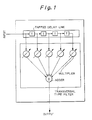
- FIG. 1 shows a typical construction of a transversal type adaptive filter which is conventionally used for equalizing waveforms of received signals.
- the transversal type adaptive filter comprises: a tapped delay line holding a time series of data which is sampled from a received signal which is to be equalized; adaptive multipliers which multiply the time series of data by respective weight coefficients; and an adder which calculates a sum of the outputs of the multipliers.
- the weight coefficients are adaptively determined to realize an equalization of the received signal.
- the waveform equalizer using the transversal type adaptive filter cannot eliminate the non-linear distorsion in the received signal.
- An object of the present invention is to provide a waveform equalizer which can adaptively respond to time-dependently varying distorsion including non-linear distorsion in a waveform of a received signal, and can realize high-speed, highly precise equalization of the signal.
- a waveform equalizer for equalizing a distorted signal, comprising: a sampling unit for sampling a level of the distorted signal at a predetermined rate; a time series generating unit for serially receiving the sampled level and outputting in parallel a predetermined number of the levels which have been last received; and an equalization neural network unit for receiving the outputs of the time series generating unit, and generating an equalized signal of the distorted signal based on the outputs of the time series generating unit using a set of equalization network weights which are preset thereto.
- a detector and waveform equalizer for detecting and equalizing a modulated and distorted signal, comprising: a sampling unit for sampling a level of the modulated and distorted signal at a predetermined rate; a time series generating unit for serially receiving the sampled level and outputting in parallel a predetermined number of the levels which have been last received; and a demodulation/equalization neural network unit for receiving the outputs of the time series generating unit, and generating a demodulated and equalized signal of the modulated and distorted signal based on the outputs of the time series generating unit using a set of demodulation/equalization network weights which are preset therein.
- a waveform equalizer comprising: in addition to the construction of the first or second aspect of the present invention; a distortion characteristic detecting unit for detecting a distortion characteristic of the distorted signal, an equalization network weight holding unit for holding a plurality of sets of equalization network weights each for being set in the equalization neural network unit; and a selector unit for selecting one of the plurality of sets of equalization network weights according to the distortion characteristic which is detected in the distortion characteristic detecting unit, and supplying the selected set to the equalization neural network unit to set the selected set therein.
- a waveform equalizer comprising: in addition to the construction of the third aspect of the present invention; an optimum equalization network weight obtaining unit for obtaining an optimum set of the equalization network weights for each distortion characteristic so that the equalization neural network unit outputs a best equalized signal for a distorted signal having that distortion characteristic when the optimum set of the equalization network weights is preset in the equalization neural network unit, and supplying the obtained set to the equalization network weight holding unit so that the equalization network weight holding unit stores therein the set of equalization network weights obtained for each of the distortion characteristics.
- a waveform equalizer comprising the same construction as the fourth aspect of the present invention, and the above optimum equalization network weight obtaining unit comprising: a model distorted signal generating unit for generating a plurality of model distorted signals each having a certain distortion characteristic, and supplying the model distorted signals to the equalization neural network unit; an equalization network weight setting unit for setting a set of equalization network weights in the equalization neural network unit; an output monitoring unit for monitoring the output of the equalization neural network unit; an equalization network weight modifying unit for modifying the set of equalization network weights which are set by the equalization network weight setting unit in the equalization neural network unit; a learning control unit for controlling the equalization network weight setting unit and the equalization network weight modifying unit based on the output of the equalization neural network unit to obtain the optimum set of the equalization network weights; and a presetting unit for presetting the obtained optimum set of the equalization network weights in the equalization neural network unit.
- the above operation may be carried out by using a simulated equalization neural network unit instead of the above equalization neural network unit.
- the simulated equalization neural network unit receives the above model distorted signals which are to be applied to the equalization neural network unit, and simulates the operation of the equalization neural network unit, in the above operation in the fifth aspect of the present invention.
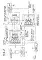
- FIG. 2 is a diagram showing the construction of the first embodiment of the present invention.
- reference numeral 10 denotes a signal sampler unit
- 20 denotes an equalizer unit
- 21 and 41 each denote a tapped delay line
- 22 denotes an equalization neural network
- 30 denotes an equalization network weights control unit
- 31 denotes an equalization network weights storage
- 32 denotes an equalization network weights selector
- 40 denotes a signal characteristics measuring unit
- 42 denotes a detection neural network
- 43 denotes a network weights setting circuit
- 50 denotes a learning controller
- 60 denotes a learning data storage unit
- 80 denotes a clock extracting circuit.
- an input signal which may include distortion and is to be equalized is sampled at a predetermined rate.
- the input signal which may contain distortion may be referred to as a distorted signal.
- the sampled level of the input signal is serially supplied to the tapped delay line 21 in the equalizer unit 20, and the tapped delay line 41 in the signal characteristics measuring unit 40.
- the tapped delay lines 21 and 41 respectively realize the aforementioned time series generating unit, and serially successively receive the sampled levels and outputs in parallel a predetermined number (five in Fig. 2) of the sampled levels which have been last received, to the equalization neural network 22 and the detection neural network 42, respectively.
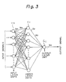
- Figure 3 is a block diagram showing input-output connections between input layer units and hidden layer units, and between the hidden layer units and the output layer units in a three layer unit neural network.
- Each of the equalization neural network 22 and the detection neural network 42 has a construction, for example, as shown in Fig. 3.
- the input layer units in each of the equalization neural network 22 and the detection neural network 42 receive the outputs of the corresponding tapped delay line 21 or 41, each of the hidden layer units inputs the values received at a predetermined combination of the input layer units and outputs a value which is a function of the inputs thereof, and each of the output layer units inputs the outputs of a predetermined combination of the hidden layer units and outputs a value which is a function of the inputs thereof.
- the network weights W ih and W ji are respectively net in the hidden layer units and the output layer units, and each of the hidden layer units and the output layer unit comprises a linear combination unit for obtaining a linear combination of the inputs thereof using the set of the equalization network weights W ih and W ji , and a non-linear function unit for obtaining a non-linear function of the linear combination.
- Each of the hidden layer units and the output layer unit in the neural network can be realized by an analog neuroprocessor, for example, as shown in Fig. 4.
- the analog neuroprocessor of Fig. 4 comprises an analog data processing block 101, a weight data loading block 102, and a control block 103.
- the analog data processing block 101 comprises a multiplying digital to analog converter 104, an adder 105, and a Sigmoid function converter 106.
- the above-mentioned (equalization or detection) network weights are supplied to the multiplying digital to analog converter 104 through the weight data loading block 102.
- the analog input signals are all or a part of the parallel outputs of tapped delay line 21 or 41 in the equalizer unit 20 and the tapped delay line 41 in the signal characteristics measuring unit 40.
- the network weights W i1 , W i2 , ... W in are serially supplied to the multiplying digital to analog converter 104 in the analog neuroprocessor which is used for a hidden layer unit 1′-h, and analog input signals yph corresponding to the network weights W i1 , W i2 , ...
- W in are serially supplied to the multiplying digital to analog converter 104 so that the inputs of the analog input signals yph respectively coincide with the inputs of the corresponding network weights W i1 , W i2 , ... W in .
- the multiplying digital to analog converter 104 serially outputs an analog signal having an amplitude y ph ⁇ W ih which is proportional to the multiplication of respective pairs of amplitudes of the above analog input signals and the corresponding network weights.
- the adder 105 serially receives the above analog output signals from the multiplying digital to analog converter 104, and accumulates the received signals to obtain a signal having an amplitude which is proportional to the linear combination ⁇ y ph ⁇ W ih .
- the Sigmoid function converter 106 transforms the output of the adder 105 in accordance with the Sigmoid function.
- the Sigmoid function is a non-linear function which is continuous and has a gradient equal to or more than zero.
- the analog output of the Sigmoid function converter 106 is output from the analog processing unit 101 of the analog neuroprocessor of Fig. 4, under the control of the control block 103.
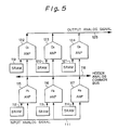
- Figure 5 is a block diagram of an example of a three layer unit neural network using the analog neuroprocessors.
- reference numeral 111 denotes an input bus
- 112 to 114, and 119 to 121 each denote a static RAM
- 115 to 117 each denote an analog neuroprocessor for a hidden layer unit
- 118 denotes an intermediate bus
- 122 to 124 each denote an analog neuroprocessor for an output layer unit
- 125 denotes an output layer unit.
- the static RAMs 112 to 114 and 119 to 121 are respectively provided for the analog neuroprocessors 115 to 117 and 122 to 124, to hold the network weights therein and supply the network weights to the corresponding analog neuroprocessors.
- the transfer of the outputs from the tapped delay line 21 or 41 to the respective analog neuroprocessors 115 to 117 in the hidden layer through the input bus 111; the transfer of the outputs from the analog neuroprocessors 115 to 117 in the hidden layer to the respective analog neuroprocessors 122 to 124 in the output layer through the intermediate bus 118; and the transfer of the outputs of the analog neuroprocessors 122 to 124 in the output layer, are respectively carried out in a time sharing manner. It is known that a transformation including a non-linear transformation can be realized by a neural network as above.
- the analog neuroprocessor is commercially available as a semi-conductor chip from Fujitsu Limited.
- a recurrent network may be used instead of the hierarchical network as shown in Figure 6 as an example.
- the recurrent network is disclosed in "Encoding Sequential Structure in Simple Recurrent Networks" by Servan-Schreiber, Axel Cleeremans, and James L. McClelland, CMU Technical Report CMU-CU-88-183, 1988. It is known that recurrent networks may be treated as equivalent to hierarchical networks.
- the equalization neural network 22 receives the outputs of the time series generating unit, and equalizes the distorted signal to generate an equalized signal, based on the outputs of the tapped delay line 21 using a set of equalization network weights which are preset therein. That is, the equalizer unit 20 containing the equalization neural network 22 operates as a waveform equalizer for the above-mentioned distorted signal when an optimum bet of the equalization network weights are set therein an explained later.
- the signal characteristics measuring unit 40 detects distortion characteristics of the distorted signal when an optimum set of the detection network weights are set therein as explained later.
- the detection neural network 42 has three outputs, which respectively output values indicating an amplitude distortion, a delay distortion, and a phase distortion, in this example.
- the equalization network weights storage 31 holds a plurality of optimum sets of equalization network weights corresponding to a plurality of possible distortion characteristics, each for being set in the equalization neural network 22, and the equalization network weights selector 32 selects one of the plurality of sets of equalization network weights according to the distortion characteristic (actually, a combination of the amplitude distortion, the delay distortion, and the phase distortion), which is detected in the distortion characteristic measuring unit 40, and supplies the selected set to the equalization neural network 22 to set the selected set therein.
- the equalization network weights selector 32 comprises a writing control circuit for the SRAMs as shown in Fig. 5 in the equalization neural network 22.
- the equalization network weights selector 32 comprises a reading/writing control circuit for the RAM, and the output of the detection neural network 42 is used as an address signal for reading the content of the RAM.
- the clock extracting unit 80 extracts a clock (timing) signal from the output (equalized) signal of the equalization unit 20. The clock signal is supplied to the equalization network weights selector 32 to provide a timing of the selection.
- the learning controller 50 obtains an optimum set of the equalization network weights for each distortion characteristic (each combination of values of the amplitude distortion, the delay distortion, and the phase distortion) so that the equalization neural network 22 outputs a best equalized signal for a distorted signal having the distortion characteristic when the optimum set of the equalization network weights is preset in the equalization neural network 22, and supplies the obtained set to the equalization network weights storage 31 so that the equalization network storage 31 stores therein the set of equalization network weights obtained for each of the distortion characteristics (each of the combinations of values of the amplitude distortions, the delay distortions, and the phase distortions).
- the equalization network weights storage 31 is a RAM, the above obtained set of the equalization network weights is written in the RAM through the above reading/writing control circuit.
- the above functions of the learning controller 50 for obtaining and supplying the optimum set of the equalization network weights through following units is realized by a software program which contains the following units: a unit for storing a model signal which is not distorted; a unit for generating a plurality of model distorted signals being respectively generated from the model signal by distorting the model signal according to a plurality of types of distortion characteristics, and supplying the model distorted signals to the equalization neural network; a unit for setting a set of equalization network weights to the equalization neural network; a unit for monitoring the output of the equalization neural network; a unit for modifying the set of equalization network weights which are set by the unit for setting the set of equalization network weights to the equalization neural network unit; a unit for controlling the unit for setting the set of equalization network weights and the unit for modifying the set of equalization network weights based on successive outputs of the equalization neural network unit so that a waveform which is made by the successive outputs of the equalization neural network unit accords to
- the above operation may be carried out by using a simulated equalization neural network unit instead of the above real equalization neural network 22.
- the simulated equalization neural network unit (by a software) receives the above model distorted signals to the equalization neural network unit, and simulates the operation of the equalization neural network 22.
- the learning controller 50 obtains an optimum set of the detection network weights which is common to all distortion characteristics (all combinations of values of the amplitude distortions, the delay distortions, and the phase distortions) so that the detection neural network 42 outputs the distortion characteristics corresponding to the distorted signals when the distorted signals after sampled by the signal sampler 10, are received by the signal characteristics measuring unit 40 when the obtained set is preset to the detection neural network 42; and presets the obtained set to the detection neural network 42.
- the above functions of the learning controller 50 for obtaining and supplying the optimum set of the detection network weights is realized by a software program which contains the following units: a unit for generating a plurality of model distorted signals each having a certain distortion characteristic, and supplying the model distorted signals to the detection neural network 42; a unit for setting a set of detection network weights to the detection neural network 42; a unit for monitoring the output of the detection neural network 42; a unit for modifying the set of detection network weights which are set in the above unit for setting the set of the detection network weights in the detection neural network 42; a unit for controlling the above unit for setting the detection network weights and the unit for modifying the detection network weights, based on the output of the detection neural network 42 to obtain the optimum set of the detection network weights; and a unit for presetting the obtained optimum set of the detection network weights in the detection neural network 42.
- the presetting is effected, for example, in the SRAMs as shown in Fig. 5.
- Any distortion including non-linear distortion can be detected as distortion values by using the neural network 42.
- the above operation may be carried out by using a simulated detection neural network unit instead of the above real detection neural network 42.
- the simulated detection neural network unit (by software) receives the above model distorted signals which are to be applied to the detection neural network 42, and simulates the operation of the detection neural network 42.
- Figures 7 and 8 are diagrams showing an example of a frame format of the input signal.
- a predetermined training data is included after a synchronization pattern SYNC, and before a real message.
- a predetermined training data is inserted intervening the real message.
- the training data is the same data as the aforementioned model distorted signal which is used for obtaining the optimum set of the detection network weights.
- the detection neural network 42 After each frame is received and sampled in the signal sampler unit 10, the sampled training data is supplied through the tapped delay line 41 to the detection neural network 42. Receiving the training data signal, the detection neural network 42 outputs the values of the amplitude distortion, the delay distortion, and the phase distortion from the three output layer units thereof.
- the equalization neural network 22 eliminates the above distortion from its input signal when the set of the equalization network weights corresponding to the distortion characteristics is set thereto. Therefore, when the real message portion of the above frame is supplied through the tapped delay line 21 to the equalization neural network 22, the real message portion of the above frame is equalized. As mentioned before, any distortion including non-linear distortion can be eliminated by using the neural network 22.
- each frame of the distorted signal sampled in the sampler unit 10 is once held in a buffer memory (not shown), and then the training data portion in the frame is first read from the buffer memory to be supplied to the detection neural network 42 as explained above, and the distortion characteristic values are determined from the distortion in the training data portion at the outputs of the detection neural network 42. Then, a set of equalization network weights corresponding to the combination of the supplied distortion characteristic values, are set in the equalization neural network 22. After that, the real message portion of the above frame is read out of the buffer memory to be supplied through the tapped delay line 21 to the equalization neural network 22, and the real message portion of the above frame is equalized.
- the training data portion can be first supplied to the signal characteristics measuring unit 40 before the real massage portion is supplied to the equalization unit 20 even when the frame format of Fig. 8 is used.
- the frame format of Fig. 8 is advantageous because the maximum time difference from the training data portion to the farthest portion of the real message portion in each frame in Fig. 8 is smaller than Fig. 7, and therefore, the maximum difference of the distortion characteristic in the training data portion and the real message portion in Fig. 8 is smaller than Fig. 7.
- Figure 9 is a diagram showing the construction of the second embodiment of the present invention.
- Fig. 9 shows the construction of the demodulation and equalization apparatus for demodulating and equalizing a received signal which is modulated by the quadrature phase shift keying (QPSK) by delay detection.
- QPSK quadrature phase shift keying
- reference numeral 20a denotes an equalizer unit, 23 and 24 each denote an equalizer, 30a denotes an equalization network weights control unit, 31a denotes an equalization network weights storage, 32a denotes an equalization network weights selector, 40a denotes a signal characteristics measuring unit, 41a, 41a′ and 41a ⁇ each denote a tapped delay line, 42a, 42a′ and 42a ⁇ each denote a detection neural network, 43 denotes a network weights setting circuit, 70 denotes a demodulator unit, 71 denotes an band pass filter, 72 denotes a limiter, 73 denotes a delay detection circuit, 74 and 76 each denote a low pass filter, 75 and 77 each denote an analog to digital converter, and 80a denotes a clock extracting circuit.
- the frequency range of the received signal which is modulated by the quadrature phase shift deying (QPSK) is limited the carrier frequency of the modulated signal by the band pass filter 71. Then, the output signal of the band pass filter 71 is transformed to a rectangular form by the limiter 72, and the I-channel and the Q-channel of the received signal is obtained by the delay detection circuit 73. The I-channel and the Q-channel are then sampled and converted to digital forms in the analog to digital converters 75 and 77 after the higher harmonic components are eliminated by the low pass filters 74 and 76, respectively. The digital sampled signals of the I-channel and the Q-channel are supplied to first and second equalization units 23 and 24, respectively. In addition, the I-channel signal is supplied to the signal characteristics measuring unit 40a.
- QPSK quadrature phase shift deying
- the existence of the limiter 72 and the delay detection circuit 73 will cause a non-linear distortion in the received signal.
- the signal characteristics measuring unit 40a comprises a plurality of detection neural network units 42a, 42a′ and 42a ⁇ which respectively receive the outputs of the tapped delay lines 41a, 41a′ and 41a ⁇ in the distortion characteristic detecting unit 40a, and generate a value indicating one of the distortion characteristics of the distorted signal based on the outputs of the corresponding one of the tapped delay lines 41a, 41a′ and 41a ⁇ using a set of detection network weights which are preset therein.
- the set of the detection network weights are determined and preset in a similar way to the first embodiment, although the learning controller 50 is not shown in Fig. 9.
- each of the plurality of detection neural network units 42a, 42a′ and 42a ⁇ outputs one of the above distortion characteristics, the amplitude distortion, the delay distortion, and the phase distortion.
- each of the plurality of detection neural network units 42a, 42a′ and 42a ⁇ outputs one of the above distortion characteristics, the amplitude distortion, the delay distortion, and the phase distortion.
- only one tapped delay line may be provided commonly to the plurality of detection neural network units 42a, 42a′ and 42a ⁇ .
- the equalization network weights storage 31a stores all the optimum sets of the equalization network weights which are to be set in the first and second equalization units 23 and 24, where the optimum sets are determined by the learning controller 50, and are stored by the equalization network weights storage 32a as in the first embodiment.
- the equalization network weights selector 32a receives the above outputs of the plurality of detection neural network units 42a, 42a′ and 42a ⁇ , and reads and sets one of the plurality of sets of the equalization network weights in the first and second equalization units 23 and 24. Therefore, the above I-channel and the Q-channel signals are respectively equalized through the first and second equalization units 23 and 24.
- the clock extracting unit 80a extracts a timing signal (clock) from the equalized I-channel signal to supply a timing of its operation.
- the function of the delay detection in the demodulation unit 70 may be included in the equalization unit 20a. That is, the first and second equalization units 23 and 24 each can operate as a demodulator at the same time as an equalizer.
- FIG. 10 is a diagram showing the construction of the third embodiment of the present invention.
- Fig. 10 shows the construction of the signal characteristics measuring unit 40b in the third embodiment of the present invention.
- reference numeral 10b denotes a signal sampler unit
- 40b denotes a signal characteristics measuring unit
- 41b and 41b′ each denote a tapped delay line
- 42b and 42b′ each denote a detection neural network
- 43b denotes a network weights setting circuit
- 44b denotes a zone selector unit
- 45b and 45b′ each denote a range selector unit.
- the signal characteristics measuring unit 40b comprises a plurality of detection neural networks 42b and 42b′.
- Each of the plurality of detection neural networks 42b and 42b′ receives the outputs of the tapped delay lines 41b and 41b′ in the distortion characteristic detecting unit 40b, generates and outputs values respectively indicating the distortion characteristics (the amplitude distortion, the delay distortion, and the phase distortion) of the distorted signal, when each of the amounts of the distortion characteristics which are contained in the distorted signal, is within a part, which is assigned to the detection neural network, of the whole range of the distortion characteristic to be detected, and generates and outputs a predetermined value (for example, the maximum value of the output range of the detection neural network units 42b and 42b′) when an amount of the detection characteristic which is contained in the distorted signal, is out of the part assigned to the detection neural network, based on the outputs of the tapped delay line in the signal characteristics measuring unit 40b using a set of detection network weights which are preset therein.
- each of the plurality of detection neural network units 42b and 42b′ outputs a value indicating one of the above distortion characteristics, the amplitude distortion, the delay distortion, and the phase distortion.
- each of the plurality of detection neural network units 42b and 42b′ outputs a value indicating one of the above distortion characteristics, the amplitude distortion, the delay distortion, and the phase distortion.
- only one tapped delay line may be provided commonly to the plurality of detection neural network units 42b and 42b′.
- the plurality of range selector units 45b and 45b′ are each provided for one of the distortion characteristics (for example, the amplitude distortion) which are detected by the signal characteristics measuring unit 40b.
- Each of the plurality of range selector units 45b and 45b′ receives the outputs of the plurality of detection neural network units 42b and 42b′ regarding one of the of distortion characteristics, and selects the output of one of the plurality of detection neural network units 42b and 42b′.
- Figure 11 is a diagram showing the construction of each of the plurality of range selector units 45b and 45b′. As shown in Fig. 11, each range selector unit comprise a selector 142 and a selector controller 141.
- the selector controller 141 in each range selector unit receives the outputs of the plurality of detection neural network units 42b and 42b′ regarding the corresponding one of the distortion characteristics, and then controls the corresponding selector 142 based on the received outputs of the plurality of detection neural network units 42b and 42b′, so that the corresponding selector selects the output of one of the detection neural network units 42b and 42b′ which does not output the predetermined value, and outputs the above predetermined value (for example, the maximum value of the output range of the detection neural network units 42b and 42b′) when all of the outputs of the detection neural network units 42b and 42b′ regarding the corresponding one of the distortion characteristics are equal to the predetermined value (the maximum value).
- the predetermined value for example, the maximum value of the output range of the detection neural network units 42b and 42b′
- the above selector controller 141 sends information on the above selection to the equalization network weights storage 32b in the equalization network weights control unit 30b. Receiving the information together with the output of the selector 141, the equalization network weights storage 32b can recognize the real amount of the distortion characteristic, and select and read the corresponding optimum set of the network weights.
- Figure 12 is a diagram showing the construction of the fourth embodiment of the present invention.
- Fig. 12 shows the construction of the signal characteristics measuring unit 40c in the fourth embodiment of the present invention.
- reference numeral 40c denotes a signal characteristics measuring unit
- 41c-1 to 41c-4 each denote a tapped delay line
- 42c-1 to 42c-4 each denote a detection neural network
- 43c denotes a network weights setting circuit
- 44c denotes a zone selector unit.
- the signal characteristics measuring unit 40c detects only two distortion characteristics, the amplitude distortion and the delay distortion.
- the signal characteristics measuring unit 40c comprises a plurality of detection neural networks 42c-1 to 42c-4.
- Each of the plurality of detection neural networks 42c-1 to 42c-4 receives the outputs of the tapped delay lines 41c-1 to 41c-4 in the distortion characteristic detecting unit 40c, generates and outputs a value respectively indicating a distortion characteristic (the amplitude distortion, the delay distortion, and the phase distortion) of the distorted signal, when an amount of the distortion characteristic which is contained in the distorted signal, is within a part, which is assigned to the detection neural network, of the whole range of the distortion characteristic to be detected, and generates and outputs a predetermined value (for example, the maximum value of the output range of the detection neural network units 42c-1 to 42c-4) when the amount of the distortion characteristic is out of the part assigned to the detection neural network, based on the outputs of the tapped delay line in the signal characteristics measuring unit 40c using a set of detection network weights which are preset therein.
- a predetermined value for example, the maximum value
- the detection neural network 42c-1 outputs a value indicating the amplitude distortion when the amplitude distortion to be detected is not more than the center value of the total range of the amplitude distortion to be detected, and outputs the maximum value of the output range of the detection neural network 42c-1 when the amount of the amplitude distortion which is contained in the distorted signal, is more than the center value of the total range of the amplitude distortion to be detected.
- the detection neural network 42c-2 outputs the value indicating the amplitude distortion when the amount of the amplitude distortion which is contained in the distorted signal, is not less than the center value of the total range of the amplitude distortion to be detected, and outputs the maximum value of the output range of the detection neural network 42c-2 when the amount of the amplitude distortion is less than the center value of the total range of the amplitude distortion to be detected.
- the detection neural network 42c-3 outputs the value indicating the delay distortion when the amount of the delay distortion is not more than the center value of the total range of the delay distortion to be detected, and outputs the maximum value of the output range of the detection neural network 42c-3 when the amount of the delay distortion is more than the center value of the total range of the delay distortion to be detected.
- the detection neural network 42c-4 outputs the value indicating the delay distortion when the amount of the delay distortion is not less than the center value of the total range of the delay distortion to be detected, and outputs the maximum value of the output range of the detection neural network 42c-4 when the amount of the delay distortion is less than the center value of the total range of the delay distortion to be detected. Therefore, each of the above values respectively indicating the amplitude distortion and the delay distortion can be output in the output range substantially twice the output range as the total ranges of the amplitude distortion or the delay distortion is output from one detection neural network.
- the zone selector unit 45c has the same construction as the above-mentioned third embodiment except that only two distortion characteristics are shown in the fourth embodiment.
- Table 1 shows the range assignment for the amplitude distortion and the delay distortion, where the range 0 to 1.0 is assigned to each of the detection neural network units 42c-1 to 42c-4.
- A, B, C, and D each denote a zone which is determined by a combination of the ranges of the amplitude distortion and the delay distortion.
- each of the above values respectively indicating the amplitude distortion and the delay distortion can be output in the output range substantially twice the output range as the total ranges of the amplitude distortion or the delay distortion is output from one detection neural network.
- the set of the detection network weights are determined and preset in a similar way to the first embodiment, although the learning controller 50 is not shown in Fig. 12. Further, instead of providing the plurality of tapped delay lines 41c-1 to 41c-4 for the plurality of detection neural network units 42c-1 to 42c-4, only one tapped delay line may be provided commonly to the plurality of detection neural network units 42c-1 to 42c-4.
- the whole output range of each detection neural network is used for indicating only a part of the total range of the value of a distortion characteristic, so the precision of the distortion characteristics is improved.
- the aforementioned model distorted signals each having a certain distortion characteristic are generated based on a two-wave interference model of a signal on a transmission line.
- a signal which is received at the receiver is approximated by a superimposition of a direct non-distorted wave and a reflected wave which contains distortion such as an amplitude distortion, a delay distortion, and a phase distortion.
- a modulated signal i.e., I(t)coswct + Q(t)sinwct is transmitted from a sender side
- the reflected wave in the I-channel is expressed an A ⁇ (I(t- ⁇ )cos ⁇ a (t- ⁇ ) + Q(t- ⁇ )sin ⁇ c (t- ⁇ )), where A denotes the amplitude distortion, ⁇ denotes the delay distortion which is normalized as 0 ⁇ ⁇ ⁇ 1, and ⁇ denotes the phase distortion which is normalized as 0 ⁇ ⁇ ⁇ 1.
- a predetermined successive data pattern for example, "010” is received on the I-channel, waveforms of demodulated signals (corresponding to the input of the equalization unit 20 of Fig. 2) corresponding to the reception of the pattern "010” which contain distortion corresponding to various values for the amplitude distortion A, the delay distortion ⁇ , and the phase distortion ⁇ , are generated by computer simulations, and the waveforms of the portion "10" in the above pattern "010” is extracted for use as learning signals (the model distorted signals).
- the first bit “0” is provided only for stabilizing the waveforms corresponding to the following bits "10", and therefore, is discarded after the above simulation.
- the above pattern "10" with the preceding bit "0” is predetermined to be the same as the aforementioned training data, i.e., the training data also contains the pattern "010".
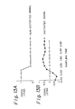
- Figure 13 is a diagram showing waveforms of the non-distorted signal corresponding to the pattern "10" and an example of a model distorted signal corresponding to the non-distorted signal
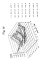
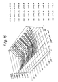
- Figures 14 and 15 are each a diagram showing the waveforms of the distorted signals which are obtained as above for the data pattern "10" and the various combinations of values of the amplitude distortions A and the delay distortions ⁇ .
- the value of the amplitude distortion A is varied from 0.1 to 0.9, and the value of the delay distortion ⁇ is fixed to 0.8. It is assumed that the signal levels are inverted through the demodulation in the simulations.
- seven samples of signal levels are shown for each simulation case, where the sampling rate is four times the Baud rate of the signal.
- the waveform data and the corresponding combinations of the distortion characteristic values are stored in the learning data storage unit 60 (Fig. 2).
- the model simulated signals have been prepared.
- the index p is used for indicating different input signals (corresponding to different model distorted signals containing different distortion characteristics)
- h is used for different input layer units
- i is used for different hidden layer units
- j is used for indicating generaly different output layer units (although only one output layer unit is shown in Fig. 3).
- ⁇ and ⁇ each denote a constant, and t denotes a number of learning cycles.
- ⁇ pi y pi ⁇ (1-y pi ) ⁇ ⁇ pj ⁇ W ji (t-1) is calculated.
- a correction of the network weight between the input layer and the hidden layer is calculted as
- W ji (t) W ji (t-1) + ⁇ W ji (t), and
- W ih (t) W ih (t-1) + ⁇ Wih (t), to obtain an optimum set of the network weights W ji and W ih which leads to the above target (the aforementioned optimum) values.
- the above operation back propagation method can be used for obtaining both the equalization network weights and the detection network weights.
- the learning controller 50 presets the above-obtained optimum network weights in the detection neural network.
- the neural network is realized by software using a digital signal processor
- the obtained network weights are stored in a predetermined region of a RAM which is used by the digital signal processor.
- the learning controller 50 obtains the optimum set of the equalization network weights for each of the plurality of model distorted signals, and stores the obtained set in the equalization network weights storage 32 for each distortion characteristic corresponding to the model distorted signal.
- the signal characteristics measuring units 40, 40a, and 40b in which the optimum sets of the network weights are preset, respectively output the values of the distortion characteristics which the distorted training signal contain, as explained before.
- Tables 3 and 4 show results of simulations which have been carried out for verifying the credibility of the signal characteristics measuring unit 40c in Fig. 11.
- the simulations are carried out for smaller and larger ranges of the amplitude distortion and the delay distortion.
- Table 3 shows the possibility of the outputs for the delay distortion t with an error not more than 0.05%
- Table 4 shows the possibility of the outputs for the amplitude distortion A with an error not more than 0.05%.
- Tables 3 and 4 the above case where the input signals are respectively the above 210 model distorted signals; the above case where the input signals are respectively the above 288 model distorted signals; the case where the input signals are the 105 signals other than 210 model distorted signals; and the case where the input signals are the 144 signals other than the 288 model distorted signals are shown.
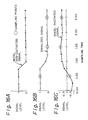
- Figure 16 is a diagram showing waveforms of the non-distorted signal corresponding to the pattern "10", an example of a model distorted signal corresponding to the non-distorted signal, and an equalized signal of the model distorted signal by simulation, where the amplitude distortion A is set to 0.1, and the delay distortion t is set to 0.1.
- Table 5 shows results (error rates) of simulations which have been carried out for verifying the credibility of the equalization unit 23 in Fig. 9.
- the simulations are carried out without the signal characteristics measuring unit 40a and the equalization network weights control unit 30a. That is, the optimum sets of the network weights are correctly set in the equalization unit 23 in the simulations.
- the output signals are sampled at the sampling points shown in Fig. 16 by circles, are digitized by discriminating the signals using a threshold level of 0.5, and are respectively compared with the non-distorted signal.
- Table 6 shows results (error rates) of simulations which have been carried out without using the equalization unit, and is provided for comparison with the above results using the equalization unit.
- equalized signals are digitized by discriminating the signals using a threshold level of 0, and are respectively compared with the non-distorted signal.
- Table 7 shows results (error rates) of simulations which have been carried out for verifying the credibility of the equalization unit 23 in Fig. 9.
- the optimum set of the network weights is obtained in the same way as the results of Table 5.
- the simulations are carried out so that the signal characteristics measuring unit 40a and the equalization network weights control unit 30a cooperate with the equalization unit 23.
- distorted signals corresponding to the pattern "10" and different from the above model distorted signals are input into the equalization unit 23, and corresponding outputs are compared with the non-distorted signal.
- the output signals are sampled at the sampling points shown in Fig. 16 by circles, are digitized by discriminating the signals using a threshold level of 0.5, and are respectively compared with the non-distorted signal. From the results of Tables 6 and 7, it is understood that the signal characteristics measuring unit 40a and the equalization network weights control unit 30a effectively cooperate with the equalization unit 23.
Landscapes
- Engineering & Computer Science (AREA)
- Physics & Mathematics (AREA)
- Artificial Intelligence (AREA)
- Evolutionary Computation (AREA)
- Theoretical Computer Science (AREA)
- Biophysics (AREA)
- Molecular Biology (AREA)
- Health & Medical Sciences (AREA)
- Life Sciences & Earth Sciences (AREA)
- Biomedical Technology (AREA)
- Computer Networks & Wireless Communication (AREA)
- Computational Linguistics (AREA)
- Data Mining & Analysis (AREA)
- General Health & Medical Sciences (AREA)
- Signal Processing (AREA)
- Computing Systems (AREA)
- General Engineering & Computer Science (AREA)
- General Physics & Mathematics (AREA)
- Mathematical Physics (AREA)
- Software Systems (AREA)
- Power Engineering (AREA)
- Cable Transmission Systems, Equalization Of Radio And Reduction Of Echo (AREA)
- Filters That Use Time-Delay Elements (AREA)
Abstract
Description
- The present invention relates to a waveform equalizer using a neural network, and a system for supervising and controlling the equalizer.
- In the field of data communications, signals suffer distortion in their waveforms during transmission thereof, and highly precise equalization of the signals is required when the signals are received to prevent an error. The distortion is often non-linear. In addition, in particular, in the field of radio communications and mobile communications, the distortion may vary time-dependently. Since the Baud rate in recent data communication is increasing, a very high speed response is required to eliminate the distortion. Thus, a waveform equalizer is required to adaptively respond to time-dependently varying distortion including non-linear distortion in a waveform of a received signal with very high speed, to realize a highly precise equalization of the signal.
- Figure 1 shows a typical construction of a transversal type adaptive filter which is conventionally used for equalizing waveforms of received signals. The transversal type adaptive filter comprises: a tapped delay line holding a time series of data which is sampled from a received signal which is to be equalized; adaptive multipliers which multiply the time series of data by respective weight coefficients; and an adder which calculates a sum of the outputs of the multipliers. The weight coefficients are adaptively determined to realize an equalization of the received signal. However, the waveform equalizer using the transversal type adaptive filter cannot eliminate the non-linear distorsion in the received signal.
- An object of the present invention is to provide a waveform equalizer which can adaptively respond to time-dependently varying distorsion including non-linear distorsion in a waveform of a received signal, and can realize high-speed, highly precise equalization of the signal.
- According to the first aspect of the present invention, there is provided a waveform equalizer for equalizing a distorted signal, comprising: a sampling unit for sampling a level of the distorted signal at a predetermined rate; a time series generating unit for serially receiving the sampled level and outputting in parallel a predetermined number of the levels which have been last received; and an equalization neural network unit for receiving the outputs of the time series generating unit, and generating an equalized signal of the distorted signal based on the outputs of the time series generating unit using a set of equalization network weights which are preset thereto.
- According to the second aspect of the present invention, there is provided a detector and waveform equalizer for detecting and equalizing a modulated and distorted signal, comprising: a sampling unit for sampling a level of the modulated and distorted signal at a predetermined rate; a time series generating unit for serially receiving the sampled level and outputting in parallel a predetermined number of the levels which have been last received; and a demodulation/equalization neural network unit for receiving the outputs of the time series generating unit, and generating a demodulated and equalized signal of the modulated and distorted signal based on the outputs of the time series generating unit using a set of demodulation/equalization network weights which are preset therein.
- According to the third aspect of the present invention, there is provided a waveform equalizer comprising: in addition to the construction of the first or second aspect of the present invention; a distortion characteristic detecting unit for detecting a distortion characteristic of the distorted signal, an equalization network weight holding unit for holding a plurality of sets of equalization network weights each for being set in the equalization neural network unit; and a selector unit for selecting one of the plurality of sets of equalization network weights according to the distortion characteristic which is detected in the distortion characteristic detecting unit, and supplying the selected set to the equalization neural network unit to set the selected set therein.
- According to the fourth aspect of the present invention, there is provided a waveform equalizer comprising: in addition to the construction of the third aspect of the present invention; an optimum equalization network weight obtaining unit for obtaining an optimum set of the equalization network weights for each distortion characteristic so that the equalization neural network unit outputs a best equalized signal for a distorted signal having that distortion characteristic when the optimum set of the equalization network weights is preset in the equalization neural network unit, and supplying the obtained set to the equalization network weight holding unit so that the equalization network weight holding unit stores therein the set of equalization network weights obtained for each of the distortion characteristics.
- According to the fifth aspect of the present invention, there is provided a waveform equalizer comprising the same construction as the fourth aspect of the present invention, and the above optimum equalization network weight obtaining unit comprising: a model distorted signal generating unit for generating a plurality of model distorted signals each having a certain distortion characteristic, and supplying the model distorted signals to the equalization neural network unit; an equalization network weight setting unit for setting a set of equalization network weights in the equalization neural network unit; an output monitoring unit for monitoring the output of the equalization neural network unit; an equalization network weight modifying unit for modifying the set of equalization network weights which are set by the equalization network weight setting unit in the equalization neural network unit; a learning control unit for controlling the equalization network weight setting unit and the equalization network weight modifying unit based on the output of the equalization neural network unit to obtain the optimum set of the equalization network weights; and a presetting unit for presetting the obtained optimum set of the equalization network weights in the equalization neural network unit.
- The above operation may be carried out by using a simulated equalization neural network unit instead of the above equalization neural network unit. The simulated equalization neural network unit receives the above model distorted signals which are to be applied to the equalization neural network unit, and simulates the operation of the equalization neural network unit, in the above operation in the fifth aspect of the present invention.
- In the drawings:
- Figure 1 is a diagram showing a typical construction of a transversal type adaptive filter which is conventionally used for equalizing waveforms of received signals;
- Figure 2 is a diagram showing the construction of the first embodiment of the present invention;
- Figure 3 is a block diagram showing input-output connections between input layer units, hidden layer units, and output layer units in a three layer unit neural network;
- Figure 4 is a block diagram of an analog neuroprocessor;
- Figure 5 is a block diagram of an example of three layer unit neural network using the analog neuroprocessors;
- Figure 6 is a block diagram of an example of recurrent network which may be used instead of the hierarchical network;
- Figures 7 and 8 are diagrams showing an example of a frame format of the input signal;
- Figure 9 is a diagram showing the construction of the second embodiment of the present invention;
- Figure 10 is a diagram showing the construction of the third embodiment of the present invention;
- Figure 11 is a diagram showing the construction of the range selector unit in the construction of Fig. 10;
- Figure 12 is a diagram showing the construction of the fourth embodiment of the present invention;
- Figure 13 is a diagram showing waveforms of the non-distorted signal corresponding to the pattern "10" and an example of a model distorted signal corresponding to the non-distorted signal;
- Figures 14 and 15 are diagrams showing the waveforms of the distorted signals which are obtained for the data pattern "10" and the various combinations of values of the amplitude distortions A and the delay distortions τ; and
- Figure 16 is a diagram showing waveforms of the non-distorted signal corresponding the the pattern "10", an example of a model distorted signal corresponding to the non-distorted signal, and an equalized signal of the model distorted signal by simulation
-
- Figure 2 is a diagram showing the construction of the first embodiment of the present invention. In Fig. 2,
reference numeral 10 denotes a signal sampler unit, 20 denotes an equalizer unit, 21 and 41 each denote a tapped delay line, 22 denotes an equalization neural network, 30 denotes an equalization network weights control unit, 31 denotes an equalization network weights storage, 32 denotes an equalization network weights selector, 40 denotes a signal characteristics measuring unit, 42 denotes a detection neural network, 43 denotes a network weights setting circuit, 50 denotes a learning controller, 60 denotes a learning data storage unit, and 80 denotes a clock extracting circuit. - In the
signal sampler unit 10, an input signal which may include distortion and is to be equalized, is sampled at a predetermined rate. Hereinafter, the input signal which may contain distortion may be referred to as a distorted signal. The sampled level of the input signal is serially supplied to the tappeddelay line 21 in theequalizer unit 20, and the tappeddelay line 41 in the signalcharacteristics measuring unit 40. The tappeddelay lines neural network 22 and the detectionneural network 42, respectively. - Figure 3 is a block diagram showing input-output connections between input layer units and hidden layer units, and between the hidden layer units and the output layer units in a three layer unit neural network. Each of the equalization
neural network 22 and the detectionneural network 42 has a construction, for example, as shown in Fig. 3. As shown in Fig. 3, theneural network hidden layer units 1′-i (i=1, 2, ...), and at least oneoutput layer unit 1˝-j (j=1, 2, ...). The input layer units in each of the equalizationneural network 22 and the detectionneural network 42 receive the outputs of the corresponding tappeddelay line - Each of the hidden layer units and the output layer unit in the neural network can be realized by an analog neuroprocessor, for example, as shown in Fig. 4. The analog neuroprocessor of Fig. 4 comprises an analog
data processing block 101, a weightdata loading block 102, and acontrol block 103. The analogdata processing block 101 comprises a multiplying digital toanalog converter 104, anadder 105, and a Sigmoidfunction converter 106. The multiplying digital toanalog converter 104 and theadder 105 calculate a linear combination of its serial input signals yph or ypi (p, h, i=1, 2, ...) thereof using the set of the network weights Wih or Wji. The above-mentioned (equalization or detection) network weights are supplied to the multiplying digital toanalog converter 104 through the weightdata loading block 102. The analog input signals are all or a part of the parallel outputs of tappeddelay line equalizer unit 20 and the tappeddelay line 41 in the signalcharacteristics measuring unit 40. For example, the network weights Wi1, Wi2, ... Win, are serially supplied to the multiplying digital toanalog converter 104 in the analog neuroprocessor which is used for ahidden layer unit 1′-h, and analog input signals yph corresponding to the network weights Wi1, Wi2, ... Win are serially supplied to the multiplying digital toanalog converter 104 so that the inputs of the analog input signals yph respectively coincide with the inputs of the corresponding network weights Wi1, Wi2, ... Win. The multiplying digital toanalog converter 104 serially outputs an analog signal having an amplitude yph·Wih which is proportional to the multiplication of respective pairs of amplitudes of the above analog input signals and the corresponding network weights. Theadder 105 serially receives the above analog output signals from the multiplying digital toanalog converter 104, and accumulates the received signals to obtain a signal having an amplitude which is proportional to the linear combination Σyph·Wih. TheSigmoid function converter 106 transforms the output of theadder 105 in accordance with the Sigmoid function. The Sigmoid function is a non-linear function which is continuous and has a gradient equal to or more than zero. The analog output of the Sigmoidfunction converter 106 is output from theanalog processing unit 101 of the analog neuroprocessor of Fig. 4, under the control of thecontrol block 103. - Figure 5 is a block diagram of an example of a three layer unit neural network using the analog neuroprocessors. In Fig. 5,
reference numeral 111 denotes an input bus, 112 to 114, and 119 to 121 each denote a static RAM, 115 to 117 each denote an analog neuroprocessor for a hidden layer unit, 118 denotes an intermediate bus, 122 to 124 each denote an analog neuroprocessor for an output layer unit, and 125 denotes an output layer unit. - In the example of Fig. 5, the static RAMs 112 to 114 and 119 to 121 are respectively provided for the
analog neuroprocessors 115 to 117 and 122 to 124, to hold the network weights therein and supply the network weights to the corresponding analog neuroprocessors. The transfer of the outputs from the tappeddelay line respective analog neuroprocessors 115 to 117 in the hidden layer through theinput bus 111; the transfer of the outputs from theanalog neuroprocessors 115 to 117 in the hidden layer to therespective analog neuroprocessors 122 to 124 in the output layer through theintermediate bus 118; and the transfer of the outputs of theanalog neuroprocessors 122 to 124 in the output layer, are respectively carried out in a time sharing manner. It is known that a transformation including a non-linear transformation can be realized by a neural network as above. The analog neuroprocessor is commercially available as a semi-conductor chip from Fujitsu Limited. - Otherwise, all the above functions which are realized by the analog neuroprocessors, can be realized by software using a digital signal processor(s). In this case, signals are supplied from the
signal sampler unit 10 in a digital form to the tappeddelay lines delay lines - Although the hierarchical network is used in the above example, a recurrent network may be used instead of the hierarchical network as shown in Figure 6 as an example. The recurrent network is disclosed in "Encoding Sequential Structure in Simple Recurrent Networks" by Servan-Schreiber, Axel Cleeremans, and James L. McClelland, CMU Technical Report CMU-CU-88-183, 1988. It is known that recurrent networks may be treated as equivalent to hierarchical networks.
- Returning to Fig. 2, the equalization
neural network 22 receives the outputs of the time series generating unit, and equalizes the distorted signal to generate an equalized signal, based on the outputs of the tappeddelay line 21 using a set of equalization network weights which are preset therein. That is, theequalizer unit 20 containing the equalizationneural network 22 operates as a waveform equalizer for the above-mentioned distorted signal when an optimum bet of the equalization network weights are set therein an explained later. - The signal
characteristics measuring unit 40 detects distortion characteristics of the distorted signal when an optimum set of the detection network weights are set therein as explained later. As shown in Fig. 2, the detectionneural network 42 has three outputs, which respectively output values indicating an amplitude distortion, a delay distortion, and a phase distortion, in this example. - The equalization
network weights storage 31 holds a plurality of optimum sets of equalization network weights corresponding to a plurality of possible distortion characteristics, each for being set in the equalizationneural network 22, and the equalizationnetwork weights selector 32 selects one of the plurality of sets of equalization network weights according to the distortion characteristic (actually, a combination of the amplitude distortion, the delay distortion, and the phase distortion), which is detected in the distortioncharacteristic measuring unit 40, and supplies the selected set to the equalizationneural network 22 to set the selected set therein. The equalizationnetwork weights selector 32 comprises a writing control circuit for the SRAMs as shown in Fig. 5 in the equalizationneural network 22. When the equalizationnetwork weights storage 31 is realized by a RAM, the equalizationnetwork weights selector 32 comprises a reading/writing control circuit for the RAM, and the output of the detectionneural network 42 is used as an address signal for reading the content of the RAM. Theclock extracting unit 80 extracts a clock (timing) signal from the output (equalized) signal of theequalization unit 20. The clock signal is supplied to the equalizationnetwork weights selector 32 to provide a timing of the selection. - The learning
controller 50 obtains an optimum set of the equalization network weights for each distortion characteristic (each combination of values of the amplitude distortion, the delay distortion, and the phase distortion) so that the equalizationneural network 22 outputs a best equalized signal for a distorted signal having the distortion characteristic when the optimum set of the equalization network weights is preset in the equalizationneural network 22, and supplies the obtained set to the equalizationnetwork weights storage 31 so that theequalization network storage 31 stores therein the set of equalization network weights obtained for each of the distortion characteristics (each of the combinations of values of the amplitude distortions, the delay distortions, and the phase distortions). When the equalizationnetwork weights storage 31 is a RAM, the above obtained set of the equalization network weights is written in the RAM through the above reading/writing control circuit. - The above functions of the learning
controller 50 for obtaining and supplying the optimum set of the equalization network weights through following units is realized by a software program which contains the following units:
a unit for storing a model signal which is not distorted;
a unit for generating a plurality of model distorted signals being respectively generated from the model signal by distorting the model signal according to a plurality of types of distortion characteristics, and supplying the model distorted signals to the equalization neural network;
a unit for setting a set of equalization network weights to the equalization neural network;
a unit for monitoring the output of the equalization neural network;
a unit for modifying the set of equalization network weights which are set by the unit for setting the set of equalization network weights to the equalization neural network unit;
a unit for controlling the unit for setting the set of equalization network weights and the unit for modifying the set of equalization network weights based on successive outputs of the equalization neural network unit so that a waveform which is made by the successive outputs of the equalization neural network unit accords to the waveform of the model signal, to obtain the optimum set of the equalization network weights for each of the plurality of model distorted signals; and
a unit for controlling an operation of storing the obtained optimum set of the equalization network weights for each of the plurality of model distorted signals, in the equalizationnetwork weights storage 31. - The above operation may be carried out by using a simulated equalization neural network unit instead of the above real equalization
neural network 22. The simulated equalization neural network unit (by a software) receives the above model distorted signals to the equalization neural network unit, and simulates the operation of the equalizationneural network 22. - Similarly, the learning
controller 50 obtains an optimum set of the detection network weights which is common to all distortion characteristics (all combinations of values of the amplitude distortions, the delay distortions, and the phase distortions) so that the detectionneural network 42 outputs the distortion characteristics corresponding to the distorted signals when the distorted signals after sampled by thesignal sampler 10, are received by the signalcharacteristics measuring unit 40 when the obtained set is preset to the detectionneural network 42; and presets the obtained set to the detectionneural network 42. - The above functions of the learning
controller 50 for obtaining and supplying the optimum set of the detection network weights is realized by a software program which contains the following units:
a unit for generating a plurality of model distorted signals each having a certain distortion characteristic, and supplying the model distorted signals to the detectionneural network 42;
a unit for setting a set of detection network weights to the detectionneural network 42;
a unit for monitoring the output of the detectionneural network 42;
a unit for modifying the set of detection network weights which are set in the above unit for setting the set of the detection network weights in the detectionneural network 42;
a unit for controlling the above unit for setting the detection network weights and the unit for modifying the detection network weights, based on the output of the detectionneural network 42 to obtain the optimum set of the detection network weights; and
a unit for presetting the obtained optimum set of the detection network weights in the detectionneural network 42. The presetting is effected, for example, in the SRAMs as shown in Fig. 5. - Any distortion including non-linear distortion can be detected as distortion values by using the
neural network 42. - The above operation may be carried out by using a simulated detection neural network unit instead of the above real detection
neural network 42. The simulated detection neural network unit (by software) receives the above model distorted signals which are to be applied to the detectionneural network 42, and simulates the operation of the detectionneural network 42. - The details of an example of the above operations of the learning
controller 50, are explained later. - Figures 7 and 8 are diagrams showing an example of a frame format of the input signal. In the frame format of Fig. 7, a predetermined training data is included after a synchronization pattern SYNC, and before a real message. On the other hand, in the frame format of Fig. 8, a predetermined training data is inserted intervening the real message. The training data is the same data as the aforementioned model distorted signal which is used for obtaining the optimum set of the detection network weights.
- First, it is assumed that the above setting of the optimum set of detection network weights in the detection
neural network 42, and the storing of the plurality of optimum sets of equalization network weights are completed. In the case the frame format of Fig. 7 is used, after each frame is received and sampled in thesignal sampler unit 10, the sampled training data is supplied through the tappeddelay line 41 to the detectionneural network 42. Receiving the training data signal, the detectionneural network 42 outputs the values of the amplitude distortion, the delay distortion, and the phase distortion from the three output layer units thereof. These outputs are supplied to the equalizationnetwork weights selector 32, and than the equalizationnetwork weights selector 32 reads from the equalizationnetwork weights storage 31 a set of equalization network weights corresponding to the combination of the supplied values of the amplitude distortion, the delay distortion, and the phase distortion, and sets the set of the equalization network weights in the equalizationneural network 22. The equalizationneural network 22 eliminates the above distortion from its input signal when the set of the equalization network weights corresponding to the distortion characteristics is set thereto. Therefore, when the real message portion of the above frame is supplied through the tappeddelay line 21 to the equalizationneural network 22, the real message portion of the above frame is equalized. As mentioned before, any distortion including non-linear distortion can be eliminated by using theneural network 22. - In the case where the functions of Fig. 2 are realized by the digital signal processor, each frame of the distorted signal sampled in the
sampler unit 10 is once held in a buffer memory (not shown), and then the training data portion in the frame is first read from the buffer memory to be supplied to the detectionneural network 42 as explained above, and the distortion characteristic values are determined from the distortion in the training data portion at the outputs of the detectionneural network 42. Then, a set of equalization network weights corresponding to the combination of the supplied distortion characteristic values, are set in the equalizationneural network 22. After that, the real message portion of the above frame is read out of the buffer memory to be supplied through the tappeddelay line 21 to the equalizationneural network 22, and the real message portion of the above frame is equalized. Therefore, in the case where the functions of fig. 2 are realized by the digital signal processor, since the sampled values of each frame are once held in the buffer memory, the training data portion can be first supplied to the signalcharacteristics measuring unit 40 before the real massage portion is supplied to theequalization unit 20 even when the frame format of Fig. 8 is used. As understood by comparing the frame formats of Figs. 7 and 8, the frame format of Fig. 8 is advantageous because the maximum time difference from the training data portion to the farthest portion of the real message portion in each frame in Fig. 8 is smaller than Fig. 7, and therefore, the maximum difference of the distortion characteristic in the training data portion and the real message portion in Fig. 8 is smaller than Fig. 7. - Figure 9 is a diagram showing the construction of the second embodiment of the present invention. Fig. 9 shows the construction of the demodulation and equalization apparatus for demodulating and equalizing a received signal which is modulated by the quadrature phase shift keying (QPSK) by delay detection. In the construction of Fig. 9,
reference numeral 20a denotes an equalizer unit, 23 and 24 each denote an equalizer, 30a denotes an equalization network weights control unit, 31a denotes an equalization network weights storage, 32a denotes an equalization network weights selector, 40a denotes a signal characteristics measuring unit, 41a, 41a′ and 41a˝ each denote a tapped delay line, 42a, 42a′ and 42a˝ each denote a detection neural network, 43 denotes a network weights setting circuit, 70 denotes a demodulator unit, 71 denotes an band pass filter, 72 denotes a limiter, 73 denotes a delay detection circuit, 74 and 76 each denote a low pass filter, 75 and 77 each denote an analog to digital converter, and 80a denotes a clock extracting circuit. The frequency range of the received signal which is modulated by the quadrature phase shift deying (QPSK) is limited the carrier frequency of the modulated signal by theband pass filter 71. Then, the output signal of theband pass filter 71 is transformed to a rectangular form by thelimiter 72, and the I-channel and the Q-channel of the received signal is obtained by thedelay detection circuit 73. The I-channel and the Q-channel are then sampled and converted to digital forms in the analog todigital converters second equalization units - In the above construction of the
modulation unit 70, the existence of thelimiter 72 and thedelay detection circuit 73 will cause a non-linear distortion in the received signal. - As shown in Fig. 9, the signal characteristics measuring unit 40a comprises a plurality of detection neural network units 42a, 42a′ and 42a˝ which respectively receive the outputs of the tapped
delay lines delay lines controller 50 is not shown in Fig. 9. For example, each of the plurality of detection neural network units 42a, 42a′ and 42a˝ outputs one of the above distortion characteristics, the amplitude distortion, the delay distortion, and the phase distortion. Further, instead of providing the plurality of tappeddelay lines - The equalization
network weights storage 31a stores all the optimum sets of the equalization network weights which are to be set in the first andsecond equalization units controller 50, and are stored by the equalizationnetwork weights storage 32a as in the first embodiment. - The equalization
network weights selector 32a receives the above outputs of the plurality of detection neural network units 42a, 42a′ and 42a˝, and reads and sets one of the plurality of sets of the equalization network weights in the first andsecond equalization units second equalization units clock extracting unit 80a extracts a timing signal (clock) from the equalized I-channel signal to supply a timing of its operation. - Further, the function of the delay detection in the
demodulation unit 70 may be included in theequalization unit 20a. That is, the first andsecond equalization units - Figure 10 is a diagram showing the construction of the third embodiment of the present invention. Fig. 10 shows the construction of the signal
characteristics measuring unit 40b in the third embodiment of the present invention. In the construction of Fig. 10,reference numeral 10b denotes a signal sampler unit, 40b denotes a signal characteristics measuring unit, 41b and 41b′ each denote a tapped delay line, 42b and 42b′ each denote a detection neural network, 43b denotes a network weights setting circuit, and 44b denotes a zone selector unit, and 45b and 45b′ each denote a range selector unit. - As shown in Fig. 10, the signal
characteristics measuring unit 40b comprises a plurality of detectionneural networks neural networks delay lines characteristic detecting unit 40b, generates and outputs values respectively indicating the distortion characteristics (the amplitude distortion, the delay distortion, and the phase distortion) of the distorted signal, when each of the amounts of the distortion characteristics which are contained in the distorted signal, is within a part, which is assigned to the detection neural network, of the whole range of the distortion characteristic to be detected, and generates and outputs a predetermined value (for example, the maximum value of the output range of the detectionneural network units characteristics measuring unit 40b using a set of detection network weights which are preset therein. The set of the detection network weights are determined and preset in a similar way to the first embodiment, although the learningcontroller 50 is not shown in Fig. 10. For example, each of the plurality of detectionneural network units delay lines neural network units neural network units - The plurality of
range selector units characteristics measuring unit 40b. Each of the plurality ofrange selector units neural network units neural network units range selector units selector 142 and aselector controller 141. - The
selector controller 141 in each range selector unit receives the outputs of the plurality of detectionneural network units corresponding selector 142 based on the received outputs of the plurality of detectionneural network units neural network units neural network units neural network units - The
above selector controller 141 sends information on the above selection to the equalization network weights storage 32b in the equalization network weights control unit 30b. Receiving the information together with the output of theselector 141, the equalization network weights storage 32b can recognize the real amount of the distortion characteristic, and select and read the corresponding optimum set of the network weights. - According to the above construction of Figs. 10 and 11, the whole output range of each detection neural network is used for indicating only a part of the total range of the value of a distortion characteristic, the precision of the distortion characteristics is improved.
-
- Figure 12 is a diagram showing the construction of the fourth embodiment of the present invention. Fig. 12 shows the construction of the signal
characteristics measuring unit 40c in the fourth embodiment of the present invention. In the construction of Fig. 12,reference numeral 40c denotes a signal characteristics measuring unit, 41c-1 to 41c-4 each denote a tapped delay line, 42c-1 to 42c-4 each denote a detection neural network, 43c denotes a network weights setting circuit, and 44c denotes a zone selector unit. In Fig. 12, for simplicity of the explanation, it is assumed that the signalcharacteristics measuring unit 40c detects only two distortion characteristics, the amplitude distortion and the delay distortion. - As shown in Fig. 12, the signal
characteristics measuring unit 40c comprises a plurality of detectionneural networks 42c-1 to 42c-4. Each of the plurality of detectionneural networks 42c-1 to 42c-4 receives the outputs of the tappeddelay lines 41c-1 to 41c-4 in the distortioncharacteristic detecting unit 40c, generates and outputs a value respectively indicating a distortion characteristic (the amplitude distortion, the delay distortion, and the phase distortion) of the distorted signal, when an amount of the distortion characteristic which is contained in the distorted signal, is within a part, which is assigned to the detection neural network, of the whole range of the distortion characteristic to be detected, and generates and outputs a predetermined value (for example, the maximum value of the output range of the detectionneural network units 42c-1 to 42c-4) when the amount of the distortion characteristic is out of the part assigned to the detection neural network, based on the outputs of the tapped delay line in the signalcharacteristics measuring unit 40c using a set of detection network weights which are preset therein. - For example, the detection
neural network 42c-1 outputs a value indicating the amplitude distortion when the amplitude distortion to be detected is not more than the center value of the total range of the amplitude distortion to be detected, and outputs the maximum value of the output range of the detectionneural network 42c-1 when the amount of the amplitude distortion which is contained in the distorted signal, is more than the center value of the total range of the amplitude distortion to be detected. The detectionneural network 42c-2 outputs the value indicating the amplitude distortion when the amount of the amplitude distortion which is contained in the distorted signal, is not less than the center value of the total range of the amplitude distortion to be detected, and outputs the maximum value of the output range of the detectionneural network 42c-2 when the amount of the amplitude distortion is less than the center value of the total range of the amplitude distortion to be detected. The detectionneural network 42c-3 outputs the value indicating the delay distortion when the amount of the delay distortion is not more than the center value of the total range of the delay distortion to be detected, and outputs the maximum value of the output range of the detectionneural network 42c-3 when the amount of the delay distortion is more than the center value of the total range of the delay distortion to be detected. The detectionneural network 42c-4 outputs the value indicating the delay distortion when the amount of the delay distortion is not less than the center value of the total range of the delay distortion to be detected, and outputs the maximum value of the output range of the detectionneural network 42c-4 when the amount of the delay distortion is less than the center value of the total range of the delay distortion to be detected. Therefore, each of the above values respectively indicating the amplitude distortion and the delay distortion can be output in the output range substantially twice the output range as the total ranges of the amplitude distortion or the delay distortion is output from one detection neural network. - The zone selector unit 45c has the same construction as the above-mentioned third embodiment except that only two distortion characteristics are shown in the fourth embodiment.


- Table 1 shows the range assignment for the amplitude distortion and the delay distortion, where the
range 0 to 1.0 is assigned to each of the detectionneural network units 42c-1 to 42c-4. In Table 1, A, B, C, and D each denote a zone which is determined by a combination of the ranges of the amplitude distortion and the delay distortion. Further, as shown in Table 2, in each zone, each of the above values respectively indicating the amplitude distortion and the delay distortion can be output in the output range substantially twice the output range as the total ranges of the amplitude distortion or the delay distortion is output from one detection neural network. - The set of the detection network weights are determined and preset in a similar way to the first embodiment, although the learning
controller 50 is not shown in Fig. 12. Further, instead of providing the plurality of tappeddelay lines 41c-1 to 41c-4 for the plurality of detectionneural network units 42c-1 to 42c-4, only one tapped delay line may be provided commonly to the plurality of detectionneural network units 42c-1 to 42c-4. - According to the above construction of Figs. 10 and 11, the whole output range of each detection neural network is used for indicating only a part of the total range of the value of a distortion characteristic, so the precision of the distortion characteristics is improved.
- Before the operation of the learning
controller 50 for obtaining the optimum set of the network weights, the aforementioned model distorted signals are obtained as explained below. - The aforementioned model distorted signals each having a certain distortion characteristic, are generated based on a two-wave interference model of a signal on a transmission line. According to the two-wave interference model, a signal which is received at the receiver is approximated by a superimposition of a direct non-distorted wave and a reflected wave which contains distortion such as an amplitude distortion, a delay distortion, and a phase distortion. For example, when the transmitted signal is modulated by the quadrature phase shift keying (QPSK), a modulated signal, i.e., I(t)coswct + Q(t)sinwct is transmitted from a sender side, the reflected wave in the I-channel is expressed an

- Based on the above model, it is supposed that a predetermined successive data pattern, for example, "010" is received on the I-channel, waveforms of demodulated signals (corresponding to the input of the
equalization unit 20 of Fig. 2) corresponding to the reception of the pattern "010" which contain distortion corresponding to various values for the amplitude distortion A, the delay distortion τ, and the phase distortion φ, are generated by computer simulations, and the waveforms of the portion "10" in the above pattern "010" is extracted for use as learning signals (the model distorted signals). The first bit "0" is provided only for stabilizing the waveforms corresponding to the following bits "10", and therefore, is discarded after the above simulation. The above pattern "10" with the preceding bit "0" is predetermined to be the same as the aforementioned training data, i.e., the training data also contains the pattern "010". - Figure 13 is a diagram showing waveforms of the non-distorted signal corresponding to the pattern "10" and an example of a model distorted signal corresponding to the non-distorted signal, and Figures 14 and 15 are each a diagram showing the waveforms of the distorted signals which are obtained as above for the data pattern "10" and the various combinations of values of the amplitude distortions A and the delay distortions τ. In Fig. 14, the value of the amplitude distortion A is fixed to A=0, and the values of the delay distortion τ is varied from 0.1 to 0.8. In Fig. 15, the value of the amplitude distortion A is varied from 0.1 to 0.9, and the value of the delay distortion τ is fixed to 0.8. It is assumed that the signal levels are inverted through the demodulation in the simulations. In the examples of Figs. 13 and 14, seven samples of signal levels are shown for each simulation case, where the sampling rate is four times the Baud rate of the signal.
- The waveform data and the corresponding combinations of the distortion characteristic values are stored in the learning data storage unit 60 (Fig. 2). Thus, the model simulated signals have been prepared.
- The details of an example of the functions of the learning
controller 50 for obtaining the optimum set of the network weights are explained below. For the example, the aforementioned back propagation method is explained. The explanation is made based on the construction of the hierarchical network shown in Fig. 3. - In Fig. 3, yph (p, h=1, 2, ...) denotes an input signal to the hierarchical network, and ypj (p, j=1, 2, ...) denotes an output signal of the hierarchical network, where the index p is used for indicating different input signals (corresponding to different model distorted signals containing different distortion characteristics), h is used for different input layer units, i is used for different hidden layer units, and j is used for indicating generaly different output layer units (although only one output layer unit is shown in Fig. 3). When a taget value (the above-mentioned model non-distorted signal, or an amount of a distortion characteristic, for example, an amount of the ampliture distortion A) of the output signal ypj is denoted by dpj (p, j=1, 2, ...), a difference ypj-dpj between the output signal ypj and the target value dpj is calculated, and then, a value αpj = ypj·(1-ypj)·(dpj-ypj) is calculated. Next, a correction of the network weight between the hidden layer and the output layer is calculated as

where ε and ζ each denote a constant, and t denotes a number of learning cycles. In addition, a value βpi = ypi·(1-ypi)·Σ αpj·Wji(t-1) is calculated.
Next, a correction of the network weight between the input layer and the hidden layer is calculted as
- Thus, using the above correction values ΔWji(t) and ΔWih(t), the network weight values are repeatedly modified as
- Wji(t) = Wji(t-1) + ΔWji(t), and
- Wih(t) = Wih(t-1) + ΔWih(t),
to obtain an optimum set of the network weights Wji and Wih which leads to the above target (the aforementioned optimum) values. The above operation back propagation method can be used for obtaining both the equalization network weights and the detection network weights. - In the case of obtaining the detection network weights, the learning
controller 50 presets the above-obtained optimum network weights in the detection neural network. When the neural network is realized by software using a digital signal processor, the obtained network weights are stored in a predetermined region of a RAM which is used by the digital signal processor. In the case of obtaining the equalization network weights, the learningcontroller 50 obtains the optimum set of the equalization network weights for each of the plurality of model distorted signals, and stores the obtained set in the equalizationnetwork weights storage 32 for each distortion characteristic corresponding to the model distorted signal. - In operation, when a distorted training signal corresponding to the same pattern as the model simulated signal is input, the signal
characteristics measuring units 

- Tables 3 and 4 show results of simulations which have been carried out for verifying the credibility of the signal
characteristics measuring unit 40c in Fig. 11. In Tables 3 and 4, the simulations are carried out for smaller and larger ranges of the amplitude distortion and the delay distortion. For the smaller range, thirty-five basic model distorted signals are prepared for seven points of the amplitude distortion between A=0.4 to 1.0, and five points of the delay distortion between 0.4 to 0.8, and six types of bit patterns before and after the model pattern "010" are assumed for the input signal, and therefore, 6X35=210 types of the model distorted signals are generated as input signals to obtain the optimum set of the network weights to be set to the detectionneural network 42c. For the larger range, forty-eight basic model distorted signals are prepared for eight points of the amplitude distortion between A=0.2 to 1.0, and six points of the delay distortion between 0.2 to 0.8, and six types of bit patterns before and after the model pattern "010" are assumed for the input signal, and therefore, 6X48=288 types of the model distorted signals are generated as input signals to obtain the optimum set of the network weights to be set in the detectionneural network 42c. - In the case of the smaller ranges, then, the above 210 types of the model distorted signals are input into the signal
characteristics measuring unit 40c, and it is determined whether or not the desired distortion characteristic values are output from the signalcharacteristics measuring unit 40c within the error of 0.05%, and within the error of 0.1%. Further, three types of bit patterns before and after the model pattern "010", other than the above 210 types are assumed, and therefore, 3X35=105 types of the model distorted signals are generated as input signals to the signalcharacteristics measuring unit 40c. - In the case of the above larger ranges, then, the above 288 types of the model distorted signals are input into the signal
characteristics measuring unit 40c, and it is determined whether or not the desired distortion characteristic values are output from the signalcharacteristics measuring unit 40c within the error of 0.05%, and within the error of 0.1%. Further, three types of bit patterns before and after the model pattern "010", other than the above 210 types are assumed, and therefore, 3X48=144 types of the model distorted signals are generated as input signals to the signalcharacteristics measuring unit 40c. - Table 3 shows the possibility of the outputs for the delay distortion t with an error not more than 0.05%, and Table 4 shows the possibility of the outputs for the amplitude distortion A with an error not more than 0.05%. In Tables 3 and 4, the above case where the input signals are respectively the above 210 model distorted signals; the above case where the input signals are respectively the above 288 model distorted signals; the case where the input signals are the 105 signals other than 210 model distorted signals; and the case where the input signals are the 144 signals other than the 288 model distorted signals are shown.
- Figure 16 is a diagram showing waveforms of the non-distorted signal corresponding to the pattern "10", an example of a model distorted signal corresponding to the non-distorted signal, and an equalized signal of the model distorted signal by simulation, where the amplitude distortion A is set to 0.1, and the delay distortion t is set to 0.1.

- Table 5 shows results (error rates) of simulations which have been carried out for verifying the credibility of the
equalization unit 23 in Fig. 9. In the above simulations, the optimum set of the network weights is obtained by supplying eighty model distorted signals for ten points of the amplitude distortion between A=0.1 to 1.0, and eight points of the delay distortion between 0.1 to 0.8. Then, distorted signals corresponding to the pattern "10" and different from the above model distorted signals are input into theequalization unit 23, and corresponding outputs are compared with the non-distorted signal. The simulations are carried out without the signal characteristics measuring unit 40a and the equalization network weights controlunit 30a. That is, the optimum sets of the network weights are correctly set in theequalization unit 23 in the simulations. The output signals are sampled at the sampling points shown in Fig. 16 by circles, are digitized by discriminating the signals using a threshold level of 0.5, and are respectively compared with the non-distorted signal.
- Table 6 shows results (error rates) of simulations which have been carried out without using the equalization unit, and is provided for comparison with the above results using the equalization unit. In the simulations for Table 6, equalized signals are digitized by discriminating the signals using a threshold level of 0, and are respectively compared with the non-distorted signal.

- Table 7 shows results (error rates) of simulations which have been carried out for verifying the credibility of the
equalization unit 23 in Fig. 9. In the above simulations, the optimum set of the network weights is obtained in the same way as the results of Table 5. The simulations are carried out so that the signal characteristics measuring unit 40a and the equalization network weights controlunit 30a cooperate with theequalization unit 23. Then, distorted signals corresponding to the pattern "10" and different from the above model distorted signals are input into theequalization unit 23, and corresponding outputs are compared with the non-distorted signal. The output signals are sampled at the sampling points shown in Fig. 16 by circles, are digitized by discriminating the signals using a threshold level of 0.5, and are respectively compared with the non-distorted signal. From the results of Tables 6 and 7, it is understood that the signal characteristics measuring unit 40a and the equalization network weights controlunit 30a effectively cooperate with theequalization unit 23.
Claims (32)
- A waveform equalizer for equalizing a distorted signal, comprising:
a sampling means (10) for sampling a level of said distorted signal at a predetermined rate;
a time series generating means (21) for serially receiving said sampled level and outputting in parallel a predetermined number of the levels which have been last received; and
an equalization neural network means (22) for receiving said outputs of said time series generating means (21), and generating an equalized signal of said distorted signal based on said outputs of said time series generating means (21) using a set of equalization network weights which are preset therein. - A waveform equalizer according to claim 1, wherein said equalization neural network means (22) is a hierarchical network comprising:
a predetermined number of input layer units (1-h),
a plurality of hidden layer units (1′-i), and
an output layer unit (1˝-j);
said input layer units (1-h) receiving said outputs of said time series generating means (21), each of said hidden layer units (1′-i) inputting the received values at a predetermined combination of the input layer units (1-h) and outputting a value which is a function of the inputs thereof, and each of said output layer unit (1˝-j)s inputting the outputs of a predetermined combination of the hidden layer units (1′-i) and outputting a value which is a function of the inputs thereof;
said equalization network weights are respectively set in the hidden layer units (1′-i) and the output layer units (1˝-j);
each of said hidden layer units (1′-i) and said output layer units (1˝-j) comprising a linear combination means (104, 105) for obtaining a linear combination of the inputs thereof using said set of the equalization network weights, and a non-linear function means (106) for obtaining a non-linear function of the linear combination. - A waveform equalizer according to claim 1 or 2, further comprising:
a distortion characteristic detecting means (40) for detecting a distortion characteristic of said distorted signal;
an equalization network weight holding means (31) for holding a plurality of sets of equalization network weights each for being set in said equalization neural network means (22); and
an equalization network weight holding means (32) for selecting one of said plurality of sets of equalization network weights according to the distortion characteristic which is detected in said distortion characteristic detecting means (40), and supplying the selected set to said equalization neural network means (22) to set the selected set therein. - A waveform equalizer according to claim 3, further comprising an optimum equalization network weight obtaining means (50) for obtaining an optimum set of the equalization network weights for each distortion characteristic so that said equalization neural network means (22) outputs a best equalized signal for a distorted signal having the distortion characteristic when the optimum set of the equalization network weights is preset in the equalization neural network means (22), and supplying the obtained set to said equalization network weight holding means (31) so that the equalization network weight holding means (31) stores therein the set of equalization network weights obtained for each of the distortion characteristics.
- A waveform equalizer according to claim 4, wherein said optimum equalization network weight obtaining means (50) comprises:
a model non-distorted signal storing means (60) for storing a model signal which is not distorted;
a model distorted signal generating means for generating a plurality of model distorted signals being respectively generated from said model signal by distorting the model signal according to a plurality of types of distortion characteristics, and supplying the model distorted signals to said equalization neural network means (22);
an equalization network weight setting means for setting a set of equalization network weights in said equalization neural network means (22);
an output monitoring means for monitoring the output of said equalization neural network means (22);
an equalization network weight modifying means for modifying said set of equalization network weights which are set by said equalization network weight setting means in said equalization neural network means (22);
a learning control means for controlling said equalization network weight setting means and said equalization network weight modifying means based on successive outputs of said equalization neural network means (22) so that a waveform which is made by the successive outputs of the equalization neural network means (22) accords to the waveform of said model signal, to obtain said optimum set of the equalization network weights for each of said plurality of model distorted signals; and
a memorizing means (112 - 121) for memorizing the obtained optimum set of the equalization network weights for each of said plurality of model distorted signals. - A waveform equalizer according to claim 4, wherein said optimum equalization network weight obtaining means (50) comprises:
a model non-distorted signal storing means (60) for storing a model signal which is not distorted;
a simulated equalization neural network means (22) for receiving model distorted signals, and simulating the operation of said equalization neural network means (22);
a model distorted signal generating means for generating a plurality of model distorted signals being respectively generated from said model signal by distorting the model signal according to a plurality of types of distortion characteristics, and supplying the model distorted signals to said simulated equalization neural network means (22);
an equalization network weight setting means for setting a set of equalization network weights in said simulated equalization neural network means (22);
an output monitoring means for monitoring the output of said simulated equalization neural network means (22);
an equalization network weight modifying means for modifying said set of equalization network weights which are set by said equalization network weight setting means in said simulated equalization neural network means (22);
a learning control means for controlling said equalization network weight setting means and said equalization network weight modifying means based on successive outputs of said simulated equalization neural network means (22) so that a waveform which is made by the successive outputs of the simulated equalization neural network means (22) accords to the waveform of said model signal, to obtain said optimum set of the equalization network weights for each of said plurality of model distorted signals; and
a memorizing means (112 - 121) for memorizing the obtained optimum set of the equalization network weights for each of said plurality of model distorted signals. - A waveform equalizer according to claim 5 or 6, wherein said optimum equalization network weight obtaining means (50) controls the equalization network weight setting means and said equalization network weight modifying means in accordance with a back propagation method.
- A waveform equalizer according to any one of claim 3 to 7, wherein said distortion characteristic detecting means (40) comprises:
a time series generating means (41) for serially receiving said sampled level and outputting in parallel a predetermined number of the levels which have been last received;
a detection neural network means (42) for receiving said outputs of said time series generating means (41) in the distortion characteristic detecting means (40), and generating a distortion characteristic value of said distorted signal based on said outputs of said time series generating means (41) in the distortion characteristic detecting means (40) using a set of detection network weights which are preset therein. - A waveform equalizer according to claim 8, wherein said generation of the distortion characteristic value is carried out during a reception of a predetermined training signal.
- A waveform equalizer according to claim 9, wherein said detection neural network means (42) is a hierarchical network comprising:
a predetermined number of input layer units (1-h),
a plurality of hidden layer units (1′-i), and
at least one output layer unit (1˝-j);
said input layer units (1-h) receiving said outputs of said time series generating means (41) in the distortion characteristic detecting means (40), each of said hidden layer units (1′-i) inputting the received values at a predetermined combination of the input layer units (1-h) and outputting a value which is a function of the inputs thereof, and each of said output layer unit (1˝-j) inputting the outputs of a predetermined combination of the hidden layer units (1′-i) and outputting a value which is a function of the inputs thereof, and outputting said distortion characteristic value;
said detection network weights are respectively set in the hidden layer units (1′-i) and the output layer unit (1˝-j);
each of said hidden layer units (1′-i) and each output layer unit (1˝-j) comprising a linear combination means (104, 105) for obtaining a linear combination of the inputs thereof using said set of the detection network weights, and a non-linear function means (106) for obtaining a non-linear function of the linear combination. - A waveform equalizer according to claim 8, 9 or 10, further comprising:
an optimum detection network weight obtaining means (50) for obtaining an optimum set of the detection network weights which is common to all distortion characteristics so that said detection neural network means (42) outputs the distortion characteristics corresponding to the distorted signals when said distorted signals after being sampled by the sampling means (10), arc received by the distortion characteristic detecting means (40) when the obtained set is preset in the detection neural network means (42); and
a detection network weight presetting means for presetting the obtained set in said detection neural network means (42). - A waveform equalizer according to claim 11, wherein said optimum detection network weight obtaining means (50) comprises:
a model distorted signal generating means for generating a plurality of model distorted signals each having a certain distortion characteristic, and supplying the model distorted signals to said detection neural network means (42);
a detection network weight setting means for setting a set of detection network weights in said detection neural network means (42);
an output monitoring means for monitoring the output of said detection neural network means (42);
a detection network weight modifying means for modifying said set of detection network weights which are set by said detection network weight setting means in said detection neural network means (42);
a learning control means for controlling said detection network weight setting means and said detection network weight modifying means based on the output of said detection neural network means (42) to obtain said optimum set of the detection network weights; and
a presetting means for presetting the obtained optimum set of the detection network weights in said detection neural network means (42). - A waveform equalizer according to claim 11, wherein said optimum detection network weight obtaining means (50) comprises:
a model distorted signal generating means for generating a plurality of model distorted signals each having a certain distortion characteristic;
a simulated detection neural network means (42) for receiving the model distorted signals, and simulating the operation of said detection neural network means (42);
a detection network weight setting means for setting a set of detection network weights in said simulated detection neural network means (42);
an output monitoring means for monitoring the output of said simulated detection neural network means (42);
a detection network weight modifying means for modifying said set of detection network weights which are set by said detection network weight setting means in said simulated detection neural network means (42);
a learning control means for controlling said detection network weight setting means and said detection network weight modifying means based on the output of said simulated detection neural network means (42) to obtain said optimum set of the detection network weights; and
a presetting means for presetting the obtained optimum set of the detection network weights in said detection neural network means (42). - A waveform equalizer according to claim 12 or 13, wherein said learning control means controls the detection network weight setting means and said detection network weight modifying means in accordance with a back propagation method.
- A waveform equalizer according to any one of claims 3 to 14, in which the distortion characteristic detecting means (40) include means for detecting a plurality of distortion characteristics of the distorted signal.
- A waveform equalizer according to claim 15 , wherein said distortion characteristic contains an amplitude distortion, a delay distortion, and a phase distortion.
- A waveform equalizer according to claim 15 or 16, when dependent directly or indirectly on claim 8, wherein said distortion characteristic detecting means (40a) includes:
a plurality of the said detection neural network means (42a, 42a′, 42a˝), each of the plurality of neural networks generating a value indicating a respective one of said distortion characteristics. - A waveform equalizer according to claim 17, wherein said plurality of detection neural network means (42c-1, 42c-2, 42c-3, 42c-4) each receive said outputs of said time series generating means (41c-1, 41c-2, 41c-3, 41c-4) in the distortion characteristic detecting means (40c), generate and output a value indicating one of said distortion characteristics of said distorted signal, when an amount of the distortion characteristic which is contained in said distorted signal, is within a part, which is assigned to the detection neural network means (42c-1, 42c-2, 42c-3, 42c-4), of the whole range of the distortion characteristic to be detected, and generate and output a predetermined value when said amount of the distortion characteristic is out of said part assigned to the detection neural network means (42c-1, 42c-2, 42c-3, 42c-4), based on said outputs of said time series generating means (41c-1, 41c-2, 41c-3, 41c-4) in the distortion characteristic detecting means (40c) using a set of detection network weights which are preset therein.
- A waveform equalizer according to claim 18, further comprising:
a plurality of neural network selector means (142), each being provided for one of said distortion characteristics which are detected by said distortion characteristic detecting means (40c), each for receiving the outputs of the plurality of distortion characteristic detecting means (40c) regarding one of the of distortion characteristics, and selecting the output of one of the plurality of distortion characteristic detecting means (40c); and
a plurality of selector control means (141), each being provided for one of said plurality of neural network selector means (142), each for receiving the outputs of the plurality of distortion charateristic detecting means (40c) regarding the corresponding one of the distortion one of the plurality of neural network selector means (142) based on the received outputs of the plurality of distortion characteristic detecting means (40c), so that the corresponding neural network selector means (142) selects the output of one of said neural network selector means (142) which does not output said predetermined value, and outputs the maximum value of the output range of said detection neural network means (42c-1, 42c-2, 42c-3, 42c-4) when all of the outputs of the plurality of distortion characteristic detecting means (40c) regarding the corresponding one of the distortion characteristics are equal to the maximum value. - A waveform equalizer according to claim 19, wherein said selector control means (141) sends information on said selection to said equalization network weight holding means (32), and
said equalization network weight holding means (32) receives said information together with said output of the neural network selector means (142), and selects the corresponding optimum set of the network weights based on the information and the output of the neural network selector means (142). - A waveform equalizer according to claim 15 or 16, wherein said distortion characteristic detecting means (40b) comprises:
a time series generating means (41b, 41b′) for serially receiving said sampled level and outputting in parallel a predetermined number of the levels which have been last received;
a plurality of the said detection neural network means (42b, 42b′) each for receiving said outputs of said time series generating means (41b, 41b′) in the distortion characteristic detecting means (40b), generating and outputting values respectively indicating said distortion characteristics of said distorted signal, when each of amounts indicating the distortion characteristics which are contained in said distorted signal, is within a part, which is assigned to the detection neural network means (42b, 42b′), of the whole range of the distortion characteristic to be detected, and generating and outputting a predetermined value when said value indicating the detection characteristic is out of said part assigned to the detection neural network means (42b, 42b′), based on said outputs of said time series generating means (41b, 41b′) in the distortion characteristic detecting means (40b) using a set of detection network weights which are preset therein. - A waveform equalizer according to claim 21, further comprising:
a plurality of neural network selector means (142), each being provided for one of said distortion characteristics which are detected by said distortion characteristic detecting means (40b), each for receiving the outputs of the distortion characteristic detecting means (40b) regarding one of the of distortion characteristics, and selecting the output of one of the plurality of detection neural network means (42b, 42b′); and
a plurality of selector control means (141), each being provided for one of said plurality of neural network selector means (142), each for receiving the outputs of distortion characteristic detecting means (40b) regarding the corresponding one of the distortion characteristics, and the controlling the corresponding one of the plurality of neural network selector means (142) based on the received outputs of the distortion characteristic detecting means (40b) regarding the corresponding on of the distortion characteristics, so that the corresponding neural network selector means (142) selects the output of one of said neural network means which does not output said predetermined value, and outputs the predetermined value of the output range of said detection neural network means (42b, 42b′) when all of the outputs of the distortion characteristic detecting means regarding the corresponding one of the distortion characteristics are equal to the predetermined value. - A waveform equalizer according to claim 22, wherein said selector control means (141) sends information on said selection to said equalization network weight holding means (32), and
said equalization network weight holding means (32) receives said information together with said output of the neural network selector means (142), and selects the corresponding optimum set of the network weights based on the information and the output of the neural network selector means (142). - A waveform equalizer according to claim 22 or 23, wherein said predetermined value is a maximum value of an output range of said detection neural network means (42b, 42b′).
- A waveform equalizer according to claim 22, 23 or 24 wherein said generation of the distortion characteristic values is carried out during a reception of a predetermined training signal.
- A waveform equalizer according to any one of claims 22 to 25, further comprising:
an optimlum detection network weight obtaining means (50) for obtaining an optimum set of the detection network weights which is common to all distortion characteristics so that said plurality of detection neural network means (42b, 42b′) output the distortion characteristics corresponding to the distorted signals when said distorted signals are after being sampled by the sampling means (10), are received by the distortion characteristic detecting means when the obtained set is preset in the plurality of detection neural network means (42b, 42b′); and
a detection network weight presetting means for presetting the obtained set in said plurality of detection neural network means (42b, 42b′). - A detector and waveform equalizer for detecting and equalizing a modulated and distorted signal, comprising:
a sampling means (10) for sampling a level of said modulated and distorted signal at a predetermined rate;
a time series generating means (21) for serially receiving said sampled level and outputting in parallel a predetermined number of the levels which have been last received; and
a demodulation/equalization neural network means for receiving said outputs of said time series generating means (21), and generating a demodulated and equalized signal of said modulated and distorted signal based on said outputs of said time series generating means (21) using a set of demodulation/equalization network weights which are preset therein. - A distortion characteristic detector for detecting a distortion characteristic of a distorted signal, comprising:
a time series generating means (41) for serially receiving successively sampled levels of said distorted signal and outputting in parallel a predetermined number of the levels which have been last received;
a detection neural network means (42) for receiving said outputs of said time series generating means (41), and generating a distortion characteristic value of said distorted signal based on the outputs of said time series generating means (41) using a set of detection network weights which are preset therein. - A detector according to claim 28, including a plurality of the said neural network means (42a, 42a′, 42a"), each of the said means generating a value indicating one of a plurality of distortion characteristics of said distorted signal.
- A detector according to claim 28, including a plurality of the said detection neural network means (42), each generating and outputting values respectively indicating said distortion characteristics of said distorted signal, when each of the amounts of the distortion characteristics which are contained in said distorted signal, is within a part, which is assigned to the detection neural network means, of the whole range of the distortion characteristic to be detected, and generating and outputting a predetermined value when said value indicating the detection characteristic is out of said part assigned to the detection neural network means, based on said outputs of said time series generating means (41) using a set of detection network weights which are preset therein.
- A distortion characteristic detector according to claim 30, further comprising:
a plurality of neural network selector means (142), each being provided for one of said distortion characteristics, each for receiving the outputs of the plurality of detection neural network means regarding one of the of distortion characteristics, and selecting the output of one of the plurality of detection neural network means; and
a plurality of selector control means (141), each being provided for one of said plurality of neural network selector means (142), each for receiving the outputs of the plurality of detection neural network means regarding the corresponding one of the distortion characteristics, and the controlling the corresponding one of the plurality of neural network selector means (142) based on the received outputs of the plurality of detection neural network means regarding the corresponding one of the distortion characteristics, so that the selected one of said neural network selector means (142) outputs the value indicating the distortion characteristic which is within said assigned part of the range, and outputs the maximum value of the output range of said detection neural network means when all of the outputs of the plurality of detection neural network means regarding the corresponding one of the distortion characteristics are equal to the maximum value. - A waveform equalizer according to claim 31, wherein said selector control means (141) sends information on said selection to said equalization network weight holding means (32), and
said equalization network weight holding means (32) receives said information together with said output of the neural network selector means (142), and selects the corresponding optimum set of the network weights based on the information and the output of the neural network selector means (142).
Applications Claiming Priority (8)
| Application Number | Priority Date | Filing Date | Title |
|---|---|---|---|
| JP2111194A JPH048019A (en) | 1990-04-26 | 1990-04-26 | Demodulator |
| JP111194/90 | 1990-04-26 | ||
| JP115478/90 | 1990-05-01 | ||
| JP2115478A JP2763379B2 (en) | 1990-05-01 | 1990-05-01 | Signal characteristics measurement equipment |
| JP115477/90 | 1990-05-01 | ||
| JP11547790A JPH0413316A (en) | 1990-05-01 | 1990-05-01 | Control processing system for equalizer |
| JP115479/90 | 1990-05-01 | ||
| JP2115479A JP2763380B2 (en) | 1990-05-01 | 1990-05-01 | Signal characteristics measurement equipment |
Publications (3)
| Publication Number | Publication Date |
|---|---|
| EP0454445A2 true EP0454445A2 (en) | 1991-10-30 |
| EP0454445A3 EP0454445A3 (en) | 1992-09-30 |
| EP0454445B1 EP0454445B1 (en) | 1996-07-03 |
Family
ID=27469887
Family Applications (1)
| Application Number | Title | Priority Date | Filing Date |
|---|---|---|---|
| EP91303700A Expired - Lifetime EP0454445B1 (en) | 1990-04-26 | 1991-04-24 | Waveform equalizer using a neural network |
Country Status (3)
| Country | Link |
|---|---|
| US (1) | US5272723A (en) |
| EP (1) | EP0454445B1 (en) |
| DE (1) | DE69120594T2 (en) |
Cited By (6)
| Publication number | Priority date | Publication date | Assignee | Title |
|---|---|---|---|---|
| EP0496677A2 (en) * | 1991-01-23 | 1992-07-29 | Fujitsu Limited | Adaptive equalizers |
| EP0585991A1 (en) * | 1992-08-06 | 1994-03-09 | Koninklijke Philips Electronics N.V. | Arrangement for reproducing a digital signal from a record carrier, comprising a variable equalizer |
| US5504633A (en) * | 1992-08-06 | 1996-04-02 | U.S. Philips Corporation | Apparatus, having a variable equalizer, for reproducing a digital signal from a record carrier |
| EP0752702A1 (en) * | 1995-07-07 | 1997-01-08 | Hewlett-Packard Company | Artificial neural network read channel |
| GB2351885A (en) * | 1999-06-26 | 2001-01-10 | Axeon Ltd | Neural network for real-time channel equalisation |
| WO2018160465A1 (en) | 2017-03-01 | 2018-09-07 | Intel Corporation | Neural network-based systems for high speed data links |
Families Citing this family (38)
| Publication number | Priority date | Publication date | Assignee | Title |
|---|---|---|---|---|
| JPH0683792A (en) * | 1991-06-12 | 1994-03-25 | Hitachi Ltd | Device for learning neural network and method for displaying learning pattern of neural network |
| US5630019A (en) * | 1992-05-23 | 1997-05-13 | Kabushiki Kaisha Topcon | Waveform evaluating apparatus using neural network |
| US5343404A (en) * | 1992-11-12 | 1994-08-30 | Maritec Corp. | Precision digital multimeter and waveform synthesizer for multi-signals with distorted waveforms embedded in noise |
| US5802505A (en) * | 1993-04-13 | 1998-09-01 | Matsushita Electric Industrial Co., Ltd. | Waveform signal equalizing method and apparatus and signal recording and reproducing apparatus |
| US5517585A (en) * | 1993-05-05 | 1996-05-14 | Liberty Technologies, Inc. | System and method for stable analysis of sampled transients arbitrarily aligned with their sample points |
| US5799114A (en) * | 1993-05-05 | 1998-08-25 | Liberty Technologies, Inc. | System and method for stable analysis of sampled transients arbitrarily aligned with their sample points |
| US5517667A (en) * | 1993-06-14 | 1996-05-14 | Motorola, Inc. | Neural network that does not require repetitive training |
| US5504780A (en) * | 1994-01-06 | 1996-04-02 | Bell Communications Research Inc. | Adaptive equalizer using self-learning neural network |
| US5532950A (en) * | 1994-04-25 | 1996-07-02 | Wadia Digital Corporation | Dynamic digital filter using neural networks |
| DE4415811A1 (en) * | 1994-05-05 | 1995-11-09 | Thomson Brandt Gmbh | Method for equalizing distorted data signals |
| US5642341A (en) * | 1994-09-20 | 1997-06-24 | Ricoh Corporation | CD ROM apparatus for improved tracking and signal sensing |
| JP3764269B2 (en) | 1998-03-20 | 2006-04-05 | 株式会社東芝 | Disk storage |
| US6933856B2 (en) * | 2001-08-02 | 2005-08-23 | Halliburton Energy Services, Inc. | Adaptive acoustic transmitter controller apparatus and method |
| GB2393825B (en) * | 2001-08-02 | 2006-02-15 | Halliburton Energy Serv Inc | Adaptive acoustic transmitter controller apparatus and method |
| US7245680B2 (en) * | 2003-06-04 | 2007-07-17 | Honeywell Federal Manufacturing & Technologiex, Llc | Method of differential-phase/absolute-amplitude QAM |
| US8223827B2 (en) * | 2004-05-05 | 2012-07-17 | Agere Systems Inc. | Method and apparatus for generating filter tap weights and biases for signal dependent branch metric computation |
| US8111986B1 (en) * | 2004-12-22 | 2012-02-07 | Clariphy Communications, Inc. | Testing of transmitters for communication links by software simulation of reference channel and/or reference receiver |
| US7643752B2 (en) * | 2004-12-22 | 2010-01-05 | Clariphy Communications, Inc. | Testing of transmitters for communication links by software simulation of reference channel and/or reference receiver |
| US7853149B2 (en) * | 2005-03-08 | 2010-12-14 | Clariphy Communications, Inc. | Transmitter frequency peaking for optical fiber channels |
| US7664394B2 (en) | 2005-06-30 | 2010-02-16 | Clariphy Communications, Inc. | Testing of receivers with separate linear O/E module and host used in communication links |
| US8254781B2 (en) | 2005-06-30 | 2012-08-28 | Clariphy Communications, Inc. | Testing of receivers with separate linear O/E module and host used in communication links |
| US8775341B1 (en) | 2010-10-26 | 2014-07-08 | Michael Lamport Commons | Intelligent control with hierarchical stacked neural networks |
| US9015093B1 (en) | 2010-10-26 | 2015-04-21 | Michael Lamport Commons | Intelligent control with hierarchical stacked neural networks |
| US9490995B1 (en) * | 2012-11-01 | 2016-11-08 | Juniper Networks, Inc. | Simulation system for network devices in a network |
| US20150249554A1 (en) * | 2013-06-21 | 2015-09-03 | Dhadesugoor Vaman | Adaptive demodulation method and apparatus using an artificial neural network to improve data recovery in high speed channels |
| US20160072543A1 (en) | 2014-09-10 | 2016-03-10 | Qualcomm Incorporated | Methods and Systems for Multi-Model, Multi-Layer Perceptron Based Non-Linear Interference Management in Multi-Technology Communication Devices |
| US11507807B2 (en) | 2016-09-27 | 2022-11-22 | Panasonic Intellectual Property Management Co., Ltd. | Audio signal processing device, audio signal processing method, and control program |
| US11050494B2 (en) * | 2018-08-17 | 2021-06-29 | Electronics And Telecommunications Research Institute | Signal-multiplexing apparatus and method based on machine learning |
| WO2021054118A1 (en) * | 2019-09-18 | 2021-03-25 | 日本電気株式会社 | Parameter determining device, signal transmitting device, parameter determining method, signal transmitting method, and recording medium |
| CN112598107A (en) * | 2019-10-01 | 2021-04-02 | 创鑫智慧股份有限公司 | Data processing system and data processing method thereof |
| US11804233B2 (en) * | 2019-11-15 | 2023-10-31 | Qualcomm Incorporated | Linearization of non-linearly transformed signals |
| TWI733305B (en) * | 2020-01-10 | 2021-07-11 | 瑞昱半導體股份有限公司 | Integrated circuit and artificial neural network-based method for adjusting current |
| US20220247648A1 (en) * | 2021-02-03 | 2022-08-04 | Tektronix, Inc. | Eye classes separator with overlay, and composite, and dynamic eye-trigger for humans and machine learning |
| US11923895B2 (en) | 2021-03-24 | 2024-03-05 | Tektronix, Inc. | Optical transmitter tuning using machine learning and reference parameters |
| US11923896B2 (en) | 2021-03-24 | 2024-03-05 | Tektronix, Inc. | Optical transceiver tuning using machine learning |
| US11907090B2 (en) | 2021-08-12 | 2024-02-20 | Tektronix, Inc. | Machine learning for taps to accelerate TDECQ and other measurements |
| US11940889B2 (en) | 2021-08-12 | 2024-03-26 | Tektronix, Inc. | Combined TDECQ measurement and transmitter tuning using machine learning |
| WO2024170050A1 (en) * | 2023-02-13 | 2024-08-22 | Huawei Technologies Co., Ltd. | Device and method for performing communication channel equalization in a plurality of channel scenarios using a neural network-based equalizer |
Citations (1)
| Publication number | Priority date | Publication date | Assignee | Title |
|---|---|---|---|---|
| EP0052362A1 (en) * | 1980-11-17 | 1982-05-26 | Nec Corporation | Fast start-up system for transversal equalizers |
Family Cites Families (5)
| Publication number | Priority date | Publication date | Assignee | Title |
|---|---|---|---|---|
| US3649916A (en) * | 1970-11-18 | 1972-03-14 | Hughes Aircraft Co | Automatic equalizer for communication channels |
| US4044381A (en) * | 1974-06-03 | 1977-08-23 | Hitachi, Ltd. | Automatic waveform equalizing system for television receiver |
| US4825448A (en) * | 1986-08-07 | 1989-04-25 | International Mobile Machines Corporation | Subscriber unit for wireless digital telephone system |
| JP2531699B2 (en) * | 1987-09-08 | 1996-09-04 | 株式会社日立製作所 | Waveform equalization method and device |
| US5115452A (en) * | 1990-08-02 | 1992-05-19 | At&T Bell Laboratories | Phase jitter correction arrangement |
-
1991
- 1991-04-24 DE DE69120594T patent/DE69120594T2/en not_active Expired - Fee Related
- 1991-04-24 EP EP91303700A patent/EP0454445B1/en not_active Expired - Lifetime
- 1991-04-26 US US07/691,871 patent/US5272723A/en not_active Expired - Fee Related
Patent Citations (1)
| Publication number | Priority date | Publication date | Assignee | Title |
|---|---|---|---|---|
| EP0052362A1 (en) * | 1980-11-17 | 1982-05-26 | Nec Corporation | Fast start-up system for transversal equalizers |
Non-Patent Citations (5)
| Title |
|---|
| IEEE INTERNATIONAL CONFERENCE ON ACOUSTIC, SPEECH AND SIGNAL PROCESSING (ICASSP-89, GLASGOW) vol. 2, 23 May 1989, IEEE, NEW YORK, US pages 1183 - 1186; GIBSON G. J. ET AL.: 'MULTILAYER PERCEPTRON STRUCTURES APPLIED TO ADAPTIVE EQUALISERS FOR DATA COMMUNICATIONS' * |
| IEEE INTERNATIONAL CONFERENCE ON ACOUSTIC, SPEECH AND SIGNAL PROCESSING (ICASSP-89, GLASGOW) vol. 4, 23 May 1989, IEEE, NEW YORK, US pages 2368 - 2371; GARCIA-GOMEZ R. ET AL.: 'ADAPTIVE RECEIVERS FOR REMOVING LINEAR AND NON-LINEAR INTERSYMBOL INTERFERENCE BY MEAN OF TIME DELAY NEURAL NETS (AR-TDNN)' * |
| IEEE INTERNATIONAL CONFERENCE ON COMMUNICATIONS (ICC '90) vol. 2, 15 April 1990, IEEE, NEW YORK, US pages 419 - 423; DE VECIANA G. ET AL.: 'NEURAL NET BASED CONTINUOUS PHASE MODULATION RECEIVERS' * |
| IEEE INTERNATIONAL CONFERENCE ON NEURAL NETWORKS vol. 1, 24 July 1988, IEEE, NEW YORK, US pages 263 - 270; WILLIAMS R. J.: 'ON THE USE OF BACKPROPAGATION IN ASSOCIATIVE REINFORCEMENT LEARNING' * |
| IEEE INTERNATIONAL CONFERENCE ON NEURAL NETWORKS vol. 1, 24 July 1988, IEEE, NEW YORK, US pages 401 - 408; WINTER R., WIDROW B.: 'MADALINE RULE II: A TRAINING ALGORITHM FOR NEURAL NETWORKS' * |
Cited By (10)
| Publication number | Priority date | Publication date | Assignee | Title |
|---|---|---|---|---|
| EP0496677A2 (en) * | 1991-01-23 | 1992-07-29 | Fujitsu Limited | Adaptive equalizers |
| EP0496677A3 (en) * | 1991-01-23 | 1992-09-23 | Fujitsu Limited | Adaptive equalizers |
| US5434883A (en) * | 1991-01-23 | 1995-07-18 | Fujitsu Limited | Adaptive equalizers |
| EP0585991A1 (en) * | 1992-08-06 | 1994-03-09 | Koninklijke Philips Electronics N.V. | Arrangement for reproducing a digital signal from a record carrier, comprising a variable equalizer |
| US5504633A (en) * | 1992-08-06 | 1996-04-02 | U.S. Philips Corporation | Apparatus, having a variable equalizer, for reproducing a digital signal from a record carrier |
| EP0752702A1 (en) * | 1995-07-07 | 1997-01-08 | Hewlett-Packard Company | Artificial neural network read channel |
| US5699487A (en) * | 1995-07-07 | 1997-12-16 | Hewlett-Packard Company | Artificial neural network read channel |
| GB2351885A (en) * | 1999-06-26 | 2001-01-10 | Axeon Ltd | Neural network for real-time channel equalisation |
| WO2018160465A1 (en) | 2017-03-01 | 2018-09-07 | Intel Corporation | Neural network-based systems for high speed data links |
| EP3590239A4 (en) * | 2017-03-01 | 2021-01-06 | INTEL Corporation | Neural network-based systems for high speed data links |
Also Published As
| Publication number | Publication date |
|---|---|
| EP0454445A3 (en) | 1992-09-30 |
| DE69120594D1 (en) | 1996-08-08 |
| US5272723A (en) | 1993-12-21 |
| EP0454445B1 (en) | 1996-07-03 |
| DE69120594T2 (en) | 1997-01-09 |
Similar Documents
| Publication | Publication Date | Title |
|---|---|---|
| US5272723A (en) | Waveform equalizer using a neural network | |
| CA1258296A (en) | Decision feedback equalizer with a pattern detector | |
| EP0332290A2 (en) | Equaliser for radio receiver | |
| US4097807A (en) | Automatic equalizing method and system | |
| JPH0125250B2 (en) | ||
| GB1535445A (en) | Digital data receiver | |
| AU615864B2 (en) | Demodulator with composite transversal equalizer and eye detection clock synchronizer | |
| US4327440A (en) | Signal detector for use in digital communication | |
| JPH035683B2 (en) | ||
| US4539689A (en) | Fast learn digital adaptive equalizer | |
| JP3898415B2 (en) | Automatic equalization circuit | |
| US20020027952A1 (en) | Method for automatic equalization for use in demodulating a digital multilevel modulation signal and automatic equalization circuit and receiver circuit using the method | |
| US4035625A (en) | Method and apparatus for performing binary equalization in voice-band phase-modulation modems | |
| JP2000049881A (en) | Communication system | |
| CA1157917A (en) | Fast learn digital adaptive equalizer | |
| RU2267230C1 (en) | Digital device for demodulation of discontinuous signals in multi-beam communication channel | |
| CA1162254A (en) | Method and apparatus for detecting the carrier only signal in an equaliser | |
| EP0792050A2 (en) | Distribution of reference symbols in a frame | |
| JPH0548391A (en) | Adaptive equalizer | |
| SU1113891A1 (en) | Device for adaptive receiving of digital signals | |
| SU832733A1 (en) | Digital adaptive signal corrector | |
| CA1159908A (en) | Apparatus and method for adjusting the timing of a sampling signal | |
| JP2511157B2 (en) | Automatic equalizer | |
| JPS5860858A (en) | Data transmitting, receiving, and demodulating device | |
| JPS6165538A (en) | Automatic equalizer |
Legal Events
| Date | Code | Title | Description |
|---|---|---|---|
| PUAI | Public reference made under article 153(3) epc to a published international application that has entered the european phase |
Free format text: ORIGINAL CODE: 0009012 |
|
| AK | Designated contracting states |
Kind code of ref document: A2 Designated state(s): DE FR GB |
|
| RIN1 | Information on inventor provided before grant (corrected) |
Inventor name: TAKANO, TAKESHI Inventor name: FUKUDA, EISUKE Inventor name: OHISHI, YASUYUKI Inventor name: ASAKAWA, KAZUO Inventor name: KAWABATA, KAZUO Inventor name: KIMOTO, TAKASHI |
|
| PUAL | Search report despatched |
Free format text: ORIGINAL CODE: 0009013 |
|
| AK | Designated contracting states |
Kind code of ref document: A3 Designated state(s): DE FR GB |
|
| 17P | Request for examination filed |
Effective date: 19921028 |
|
| 17Q | First examination report despatched |
Effective date: 19941108 |
|
| GRAH | Despatch of communication of intention to grant a patent |
Free format text: ORIGINAL CODE: EPIDOS IGRA |
|
| GRAH | Despatch of communication of intention to grant a patent |
Free format text: ORIGINAL CODE: EPIDOS IGRA |
|
| GRAA | (expected) grant |
Free format text: ORIGINAL CODE: 0009210 |
|
| AK | Designated contracting states |
Kind code of ref document: B1 Designated state(s): DE FR GB |
|
| PG25 | Lapsed in a contracting state [announced via postgrant information from national office to epo] |
Ref country code: FR Free format text: THE PATENT HAS BEEN ANNULLED BY A DECISION OF A NATIONAL AUTHORITY Effective date: 19960703 |
|
| REF | Corresponds to: |
Ref document number: 69120594 Country of ref document: DE Date of ref document: 19960808 |
|
| EN | Fr: translation not filed | ||
| PLBE | No opposition filed within time limit |
Free format text: ORIGINAL CODE: 0009261 |
|
| STAA | Information on the status of an ep patent application or granted ep patent |
Free format text: STATUS: NO OPPOSITION FILED WITHIN TIME LIMIT |
|
| 26N | No opposition filed | ||
| REG | Reference to a national code |
Ref country code: GB Ref legal event code: IF02 |
|
| PGFP | Annual fee paid to national office [announced via postgrant information from national office to epo] |
Ref country code: GB Payment date: 20030423 Year of fee payment: 13 |
|
| PGFP | Annual fee paid to national office [announced via postgrant information from national office to epo] |
Ref country code: DE Payment date: 20030502 Year of fee payment: 13 |
|
| PG25 | Lapsed in a contracting state [announced via postgrant information from national office to epo] |
Ref country code: GB Free format text: LAPSE BECAUSE OF NON-PAYMENT OF DUE FEES Effective date: 20040424 |
|
| PG25 | Lapsed in a contracting state [announced via postgrant information from national office to epo] |
Ref country code: DE Free format text: LAPSE BECAUSE OF NON-PAYMENT OF DUE FEES Effective date: 20041103 |
|
| GBPC | Gb: european patent ceased through non-payment of renewal fee |
Effective date: 20040424 |