EP0454202B1 - Apparatus for wrapping a food-stuff wrapper around a food-stuff core - Google Patents
Apparatus for wrapping a food-stuff wrapper around a food-stuff core Download PDFInfo
- Publication number
- EP0454202B1 EP0454202B1 EP19910200806 EP91200806A EP0454202B1 EP 0454202 B1 EP0454202 B1 EP 0454202B1 EP 19910200806 EP19910200806 EP 19910200806 EP 91200806 A EP91200806 A EP 91200806A EP 0454202 B1 EP0454202 B1 EP 0454202B1
- Authority
- EP
- European Patent Office
- Prior art keywords
- conveyor belt
- wrapper
- roller
- reversing
- core
- Prior art date
- Legal status (The legal status is an assumption and is not a legal conclusion. Google has not performed a legal analysis and makes no representation as to the accuracy of the status listed.)
- Expired - Lifetime
Links
Images

Classifications
-
- A—HUMAN NECESSITIES
- A22—BUTCHERING; MEAT TREATMENT; PROCESSING POULTRY OR FISH
- A22C—PROCESSING MEAT, POULTRY, OR FISH
- A22C7/00—Apparatus for pounding, forming, or pressing meat, sausage-meat, or meat products
-
- A—HUMAN NECESSITIES
- A21—BAKING; EDIBLE DOUGHS
- A21C—MACHINES OR EQUIPMENT FOR MAKING OR PROCESSING DOUGHS; HANDLING BAKED ARTICLES MADE FROM DOUGH
- A21C9/00—Other apparatus for handling dough or dough pieces
- A21C9/06—Apparatus for filling pieces of dough such as doughnuts
- A21C9/063—Applying a folding, wrapping, rolling action
Definitions
- the invention relates to an apparatus for wrapping a wrapper in the form of a slice- shaped or sheet-shaped food product about a substantially cylindrical core consisting of another food product, the apparatus comprising an endless conveyor belt being movable over guide rollers and reversing rollers for conveying the wrapper and the core disposed thereon.
- US-A-3,735,694 discloses the aforementioned features.
- the particular object of the invention is to mechanically produce beef-olives, i.e. a core of food product such as minced meat, in a wrapper in the form of a slice-shaped or sheet-shaped food product, such as a meat product.
- a conveyor belt for mechanically arranging a wrapper about a core in order to produce beef-olives is already known, but in these methods the wrapper is rolled. This rolling requires sufficient friction between the wrapper and the conveyor belt, but this friction may be insufficient due to e.g. ice deposition on the conveyor belt, originating from the frozen wrapper.
- the conveyor belt may provide insufficient grip on the wrapper due to moisture deposition.
- the wrapper may be too stiff for rolling.
- the wrapper may consist of a slice of meat sliced from a lump of meat formed by compressing chunks of meat, so that the slice of meat lacks natural cohesion and may fall apart into pieces.
- the invention provides an apparatus of the type referred to above, in which a first frame with at least one first guide roller mounted thereon can be swivelled from a normal position, in which the conveyor belt is substantially stretched and extends past the first guide roller and a first pair of reversing rollers, to a position in which the first guide roller is disposed over a portion of the conveyor belt that precedes the first pair of reversing rollers, and back to said normal position, a second frame with at least one second guide roller mounted thereon being simultaneously swivelled from a normal position in which the second guide roller is located under a portion of the conveyor belt that extends from a second reversing roller, to a position in which the conveyor belt is substantially stretched and extends past the second guide roller and the second reversing roller, and back to said normal position.
- the invented apparatus is characterized in that at least the first pair of reversing rollers, the two frames each with their guide rollers and the second reversing roller are disposed such that during the simultaneous swivelling of the two frames from their normal positions to their swivelled positions and when the frames have reached their swivelled positions, the tension in the conveyor belt remains at least substantially equal to the tension in the conveyor belt when the frames are in their normal positions.
- Another important embodiment of the invented apparatus is characterized in that the diameter of the first pair of reversing rollers is adapted to the diameter of the food core plus the thickness of the food wrapper to such an extent, that the wrapper can be wrapped about the core sufficiently tight.
- the invented apparatus shown in the drawing serves to wrap a wrapper 1 about a core 2.
- the core 2 may be a substantiall cylindrical body of e.g. minced meat, while the wrapping is slice-shaped or sheet-shaped and e.g. consists of meat.
- the core may also initially be a small heap of food product which is formed into a cylinder during wrapping.
- the core of minced meat and the slice of meat wrapped about it together form a beef-olive. It is clear, however, that the core and the wrapper may consist of other food products with which the invented apparatus is applied.
- the drawn embodiment of the invented apparatus comprises an endless conveyor belt 3 of which only the right-hand side has been represented in the accompanying drawing as the invention is exclusively directed to that particular end.
- the conveyor belt 3 extends to the right over a carrier roller 12, followed by third and first guide rollers 6 and 5, respectively, mounted on a first frame 13, and also underneath a first pair of reversing rollers 7, an end roll 11, fourth and second guide rollers 8 and 9, respectively, mounted on a second frame 14, and finally a second reversing roller 10.
- Both frames 13 and 14 can be simultaneously swivelled upwards from their positions as shown in figure 1 to their positions as shown in figure 4, figure 3 showing an intermediate position during swivelling, for clarity's sake.
- the two frames 13 and 14 are swivelled back to their normal positions as shown in figure 5, which positions are identical to those shown in figure 1. It is possible to couple frames 13 and 14 mechanically.
- the finished end product i.e. the core 2 with the wrapper 1 wrapped about it, is transferred by the conveyor belt 3, after the frames 13 and 14 have been swivelled back to their normal positions as shown in figure 5, to the discharge conveyor 4 which is disposed opposite the end roll 11 of the conveyor belt 3 for that purpose.
- first frame 13 can be swivelled about the shaft of the first pair of reversing rollers 7 and the second frame 14 can then preferably be swivelled about the shaft of the second reversing roller 10.
- the means that allow the frames 13 and 14 to swivel are not a part of the invention but may e.g. be an assembly of piston and cylinder.
- the conveyor belt 3 forms a loop from the carrier roller 12 via the first pair of reversing rollers 7 up to the first guide roller 5.
- the second frame 14 shortens the track of the conveyor belt 3 to the same extent as said track is simultaneously lengthened by the loop in the conveyor belt 3 when the first frame 13 is swivelled upwards, the tension in the conveyor belt 3 remains substantially the same during swivelling the frames, in the upwards position of the frames as shown in figure 4, and when the frames 13 and 14 are in their normal positions as shown in figure 1.
- the wrapper 1 is not subjected to stretch, so that the wrapper is not pulled apart into pieces. This is relevant in cases where the wrapper 1 consists of a slice of meat formed by compressing chunks of meat or else is sliced from a lump of meat formed by compressing chunks of meat, so that the slice of meat can easily fall apart into pieces on account of the lack of natural cohesion.
- the tightness with which the wrapper is wrapped about the core 2 can be adjusted to the desired extent.
- the wrapper 1 As the wrapper 1 remains almost entirely in contact with the conveyor belt 3 during wrapping, the wrapper will less easily be shifted with respect to the conveyor belt 3 than would be the case if the wrapper were rolled about the core 2.
- the conveyor belt can optionally be in motion either continuously or intermittently, the intermittent motion thus relating to the stages of the wrapping process.
Description
- The invention relates to an apparatus for wrapping a wrapper in the form of a slice- shaped or sheet-shaped food product about a substantially cylindrical core consisting of another food product, the apparatus comprising an endless conveyor belt being movable over guide rollers and reversing rollers for conveying the wrapper and the core disposed thereon. US-A-3,735,694 discloses the aforementioned features.
- The particular object of the invention is to mechanically produce beef-olives, i.e. a core of food product such as minced meat, in a wrapper in the form of a slice-shaped or sheet-shaped food product, such as a meat product. The application of a conveyor belt for mechanically arranging a wrapper about a core in order to produce beef-olives is already known, but in these methods the wrapper is rolled. This rolling requires sufficient friction between the wrapper and the conveyor belt, but this friction may be insufficient due to e.g. ice deposition on the conveyor belt, originating from the frozen wrapper. Moreover, the conveyor belt may provide insufficient grip on the wrapper due to moisture deposition. Also, the wrapper may be too stiff for rolling. Finally the wrapper may consist of a slice of meat sliced from a lump of meat formed by compressing chunks of meat, so that the slice of meat lacks natural cohesion and may fall apart into pieces.
- In order to remove these problems, the invention provides an apparatus of the type referred to above, in which a first frame with at least one first guide roller mounted thereon can be swivelled from a normal position, in which the conveyor belt is substantially stretched and extends past the first guide roller and a first pair of reversing rollers, to a position in which the first guide roller is disposed over a portion of the conveyor belt that precedes the first pair of reversing rollers, and back to said normal position, a second frame with at least one second guide roller mounted thereon being simultaneously swivelled from a normal position in which the second guide roller is located under a portion of the conveyor belt that extends from a second reversing roller, to a position in which the conveyor belt is substantially stretched and extends past the second guide roller and the second reversing roller, and back to said normal position.
- Preferably the invented apparatus is characterized in that at least the first pair of reversing rollers, the two frames each with their guide rollers and the second reversing roller are disposed such that during the simultaneous swivelling of the two frames from their normal positions to their swivelled positions and when the frames have reached their swivelled positions, the tension in the conveyor belt remains at least substantially equal to the tension in the conveyor belt when the frames are in their normal positions.
- Another important embodiment of the invented apparatus is characterized in that the diameter of the first pair of reversing rollers is adapted to the diameter of the food core plus the thickness of the food wrapper to such an extent, that the wrapper can be wrapped about the core sufficiently tight.
- The
remaining claims - The invention will be further elucidated in the following description to the accompanying drawings of a preferred embodiment of the invented apparatus.
- In these drawings:
- figure 1 shows a schematic side view of the invented apparatus in the position prior to wrapping a wrapper about the core;
- figure 2 shows a top view of the apparatus with a core and a wrapper as shown in figure 1;
- figure 3 shows a view as shown in figure 1, each of the frames being, however, in a position between the starting position as shown in figure 1 and the wrapping position in figure 4;
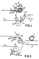
- figure 4 shows a side view as shown in figures 1 and 3, each of the two frames being, however, in the position in which the wrapper is wrapped about the core;
- figure 5 shows a view as shown in figures 1, 3 and 4, each of the two frames having been swivelled back to the position as shown in figure 1 since wrapping the wrapper about the core has been completed.
- The invented apparatus shown in the drawing serves to wrap a
wrapper 1 about acore 2. Thecore 2 may be a substantiall cylindrical body of e.g. minced meat, while the wrapping is slice-shaped or sheet-shaped and e.g. consists of meat. However, the core may also initially be a small heap of food product which is formed into a cylinder during wrapping. The core of minced meat and the slice of meat wrapped about it together form a beef-olive. It is clear, however, that the core and the wrapper may consist of other food products with which the invented apparatus is applied. - The drawn embodiment of the invented apparatus comprises an
endless conveyor belt 3 of which only the right-hand side has been represented in the accompanying drawing as the invention is exclusively directed to that particular end. - As shown in figure 1, the
conveyor belt 3 extends to the right over acarrier roller 12, followed by third andfirst guide rollers first frame 13, and also underneath a first pair ofreversing rollers 7, anend roll 11, fourth and second guide rollers 8 and 9, respectively, mounted on asecond frame 14, and finally asecond reversing roller 10. - Both
frames wrapper 1 about thecore 2 in the manner as shown in figure 4 has been completed, the twoframes frames - The finished end product, i.e. the
core 2 with thewrapper 1 wrapped about it, is transferred by theconveyor belt 3, after theframes end roll 11 of theconveyor belt 3 for that purpose. - Preferably the
first frame 13 can be swivelled about the shaft of the first pair ofreversing rollers 7 and thesecond frame 14 can then preferably be swivelled about the shaft of thesecond reversing roller 10. The means that allow theframes - With the
frames conveyor belt 3 forms a loop from thecarrier roller 12 via the first pair ofreversing rollers 7 up to thefirst guide roller 5. As by swivelling upwards, thesecond frame 14 shortens the track of theconveyor belt 3 to the same extent as said track is simultaneously lengthened by the loop in theconveyor belt 3 when thefirst frame 13 is swivelled upwards, the tension in theconveyor belt 3 remains substantially the same during swivelling the frames, in the upwards position of the frames as shown in figure 4, and when theframes - On account of this substantially unaffected tension in the
conveyor belt 3, thewrapper 1 is not subjected to stretch, so that the wrapper is not pulled apart into pieces. This is relevant in cases where thewrapper 1 consists of a slice of meat formed by compressing chunks of meat or else is sliced from a lump of meat formed by compressing chunks of meat, so that the slice of meat can easily fall apart into pieces on account of the lack of natural cohesion. - On account of the correct tension in the
conveyor belt 3 and the correct ratio between the diameter of the first pair ofreversing rollers 7 on the one hand and the diameter of thecore 2 plus the thickness of thewrapper 1 on the other hand, the tightness with which the wrapper is wrapped about thecore 2 can be adjusted to the desired extent. - As the
wrapper 1 remains almost entirely in contact with theconveyor belt 3 during wrapping, the wrapper will less easily be shifted with respect to theconveyor belt 3 than would be the case if the wrapper were rolled about thecore 2. - The conveyor belt can optionally be in motion either continuously or intermittently, the intermittent motion thus relating to the stages of the wrapping process.
Claims (7)
- Apparatus for wrapping a wrapper (1) in the form of a slice-shaped or sheet-shaped food product about a substantially cylindrical core (2) consisting of another food product, the apparatus comprising an endless conveyor belt (3) being movable over guide rollers and reversing rollers for conveying the wrapper (1) and the core (2) disposed thereon, characterized in that a first frame (13) with at least one first guide roller (5) mounted thereon can be swivelled from a normal position, in which the conveyor belt (3) is substantially stretched and extends past the first guide roller (5) and a first pair of reversing rollers (7), to a position in which the first guide roller (5) is disposed over a portion of the conveyor belt (3) that precedes the first pair of reversing rollers (7), and back to said normal position, a second frame (14) with at least one second guide roller (9) mounted thereon being simultaneously swivelled from a normal position in which the second guide roller (9) is located under a portion of the conveyor belt (3) that extends from a second reversing roller (10), to a position in which the conveyor belt (3) is substantially stretched and extends past the second guide roller (9) and the second reversing roller (10), and back to said normal position.
- Apparatus according to claim 1, characterized in that at least the first pair of reversing rollers (7), the two frames (13, 14) each with their guide rollers (5, 6, and 8, 9) and the second reversing roller (10) are disposed such that during the simultaneous swivelling of the two frames from their normal positions to their swivelled positions and when the frames (13, 14) have reached their swivelled positions, the tension in the conveyor belt (3) remains at least substantially equal to the tension in the conveyor belt when the frames (13, 14) are in their normal positions.
- Apparauts according to claim 1 or 2, characterized in that the first frame (13) comprises a third guide roller (6) for guiding the conveyor belt (3) past the first pair of reversing rollers (7) when the frame (13) is in its swivelled position.
- Apparatus according to any one of the preceding claims, characterized in that the second frame (14) comprises a fourth guide roller (8) for guiding the conveyor belt (3) past the second reversing roller (10) when the frame (14) is in its normal position.
- Apparatus according to any one of the preceding claims, characterized by an end roller (11) for the conveyor belt (3), said end roller being disposed opposite the end of a discharge conveyor (4) in such a way that when the two frames (13, 14) are in their normal positions, the conveyor belt (3) transfers the finished food product (1, 2) to the discharge conveyor (4).
- Apparatus according to any one of the preceding claims, characterized in that the diameter of the first pair of reversing rollers (7) is adapted to the diameter of the food core (2) plus the thickness of the food wrapper (1) to such an extent, that the wrapper (1) can be wrapped about the core (2) sufficiently tight.
- Apparatus according to any one of the preceding claims, characterized in that during supplying, wrapping and discharging, the conveyor belt (3) can optionally either be continuously or, adapted to the stages of the wrapping process, intermittently in motion.
Applications Claiming Priority (2)
| Application Number | Priority Date | Filing Date | Title |
|---|---|---|---|
| NL9001023 | 1990-04-27 | ||
| NL9001023A NL9001023A (en) | 1990-04-27 | 1990-04-27 | APPARATUS FOR WRAPPING A FOOD COVER AROUND A FOOD NUCLEAR. |
Publications (2)
| Publication Number | Publication Date |
|---|---|
| EP0454202A1 EP0454202A1 (en) | 1991-10-30 |
| EP0454202B1 true EP0454202B1 (en) | 1994-07-06 |
Family
ID=19857026
Family Applications (1)
| Application Number | Title | Priority Date | Filing Date |
|---|---|---|---|
| EP19910200806 Expired - Lifetime EP0454202B1 (en) | 1990-04-27 | 1991-04-05 | Apparatus for wrapping a food-stuff wrapper around a food-stuff core |
Country Status (3)
| Country | Link |
|---|---|
| EP (1) | EP0454202B1 (en) |
| DE (1) | DE69102733T2 (en) |
| NL (1) | NL9001023A (en) |
Families Citing this family (8)
| Publication number | Priority date | Publication date | Assignee | Title |
|---|---|---|---|---|
| EP0770330B1 (en) * | 1995-10-23 | 2001-06-27 | Unilever N.V. | Method and device for rolling a planar piece of material |
| AT409442B (en) * | 2000-02-15 | 2002-08-26 | Koller Roman Ing | Equipment manufacturing e.g. bacon-wrapped sausages is based on parallel conveyor bands, with curved spring bows reaching up between them |
| ITVR20010057A1 (en) * | 2001-05-10 | 2002-11-10 | Doge Food Proc Machinery Srl | LINE OF TREATMENT OF ROLLED FOOD PRODUCTS PARTICULARLY FOR THE OBTAINING OF CROISSANTS |
| ATE360994T1 (en) * | 2004-05-11 | 2007-05-15 | Rene Senn Ag | APPARATUS AND METHOD FOR ROLLING FLAT FOOD PRODUCTS |
| US8568195B1 (en) | 2008-01-15 | 2013-10-29 | Times Three Clothier, LLC | Multi-fabric garment |
| ITCN20120014A1 (en) * | 2012-10-26 | 2014-04-27 | Elcat S R L | MODULE FOR THE ROLL-UP OF FOOD-MADE FOODS |
| ITVI20130053A1 (en) * | 2013-02-28 | 2014-08-29 | Essica Srl | MACHINE FOR THE PRODUCTION OF FOOD PRODUCTS |
| CN108338388B (en) * | 2018-05-14 | 2023-05-12 | 佛山市顺德区屏荣食品发展有限公司 | Food is with rolling up system machine |
Family Cites Families (8)
| Publication number | Priority date | Publication date | Assignee | Title |
|---|---|---|---|---|
| NL29743C (en) * | 1900-01-01 | |||
| NL32938C (en) * | 1900-01-01 | |||
| DE591450C (en) * | 1928-08-30 | 1934-01-22 | Johannes Philippus Peters | Roll-up device for dough slices |
| DE1278272B (en) * | 1964-02-05 | 1968-09-19 | Nordischer Maschinenbau | Method and device for making rolls from slices of meat or fish fillet |
| US3735694A (en) * | 1970-09-04 | 1973-05-29 | Formax Inc | Rolling machine for stuffed meat {37 birds{38 {0 and other rolled articles |
| DE2718383C3 (en) * | 1977-04-26 | 1979-12-06 | Seewer Ag Maschinenfabrik, Burgdorf, Bern (Schweiz) | Dough strip winding device on a dough rolling mill |
| NL175024C (en) * | 1978-05-26 | 1984-09-17 | Bamach Bv | METHOD, COVERING AND APPARATUS FOR MANUFACTURING A FOOD PRODUCT, SUCH AS A SLAB FIN. |
| FR2611576B1 (en) * | 1987-02-26 | 1990-03-23 | Boca Ouest | METHOD AND DEVICE FOR FORMING SOFT AND STICKY PRODUCTS |
-
1990
- 1990-04-27 NL NL9001023A patent/NL9001023A/en not_active Application Discontinuation
-
1991
- 1991-04-05 DE DE1991602733 patent/DE69102733T2/en not_active Expired - Fee Related
- 1991-04-05 EP EP19910200806 patent/EP0454202B1/en not_active Expired - Lifetime
Also Published As
| Publication number | Publication date |
|---|---|
| NL9001023A (en) | 1991-11-18 |
| DE69102733D1 (en) | 1994-08-11 |
| EP0454202A1 (en) | 1991-10-30 |
| DE69102733T2 (en) | 1995-01-05 |
Similar Documents
| Publication | Publication Date | Title |
|---|---|---|
| CA1300549C (en) | Conveyors | |
| US5281120A (en) | Apparatus for producing croissants with fillings | |
| US4056346A (en) | Apparatus for processing dough | |
| US4483242A (en) | Automated food processing equipment | |
| EP0039755B1 (en) | Method and device for the production of thin slices of frozen meat | |
| EP0454202B1 (en) | Apparatus for wrapping a food-stuff wrapper around a food-stuff core | |
| US4904491A (en) | Method for producing dough for bread or pastry | |
| CA1240197A (en) | Method and apparatus for producing laminated products | |
| US5440974A (en) | Croissant dough-piece bending apparatus | |
| ES2139836T3 (en) | PROCEDURE AND APPARATUS FOR CONFORMING PIECES OF BREAD MASS IN THE FORM OF AN EXTENDED BAR. | |
| US3038418A (en) | Dough twisting machine | |
| US3677171A (en) | Apparatus for cooking strips of meat | |
| FI84423B (en) | FOERFARANDE OCH ANORDNING FOER RULLNING AV DELVIS VIKTA DEGPLATTOR. | |
| CA2070028A1 (en) | Apparatus for forming dough | |
| US5330776A (en) | Method and apparatus for preparation of rolled products | |
| JPH0343036A (en) | Dough drawing method and device therefor | |
| US4410080A (en) | Delivery device for a freezing plant | |
| EP0962142A2 (en) | Apparatus for feeding machines for making bread or the like | |
| GB2243281A (en) | Method for folding food product | |
| JP2972118B2 (en) | Rolled rice cooker | |
| JPS6041106Y2 (en) | Wrapping device for confectionery dough, etc. | |
| JPS5596085A (en) | Device for forming frying ingredient | |
| JPS6041114Y2 (en) | Shaping device in paste product manufacturing machine | |
| JPH084486B2 (en) | Rolled food manufacturing equipment | |
| ES2009978A6 (en) | Machine for making puff pastry palmiers |
Legal Events
| Date | Code | Title | Description |
|---|---|---|---|
| PUAI | Public reference made under article 153(3) epc to a published international application that has entered the european phase |
Free format text: ORIGINAL CODE: 0009012 |
|
| AK | Designated contracting states |
Kind code of ref document: A1 Designated state(s): BE DE FR GB NL |
|
| 17P | Request for examination filed |
Effective date: 19911007 |
|
| 17Q | First examination report despatched |
Effective date: 19930903 |
|
| GRAA | (expected) grant |
Free format text: ORIGINAL CODE: 0009210 |
|
| AK | Designated contracting states |
Kind code of ref document: B1 Designated state(s): BE DE FR GB NL |
|
| REF | Corresponds to: |
Ref document number: 69102733 Country of ref document: DE Date of ref document: 19940811 |
|
| ET | Fr: translation filed | ||
| PLBE | No opposition filed within time limit |
Free format text: ORIGINAL CODE: 0009261 |
|
| STAA | Information on the status of an ep patent application or granted ep patent |
Free format text: STATUS: NO OPPOSITION FILED WITHIN TIME LIMIT |
|
| 26N | No opposition filed | ||
| REG | Reference to a national code |
Ref country code: GB Ref legal event code: IF02 |
|
| PGFP | Annual fee paid to national office [announced via postgrant information from national office to epo] |
Ref country code: BE Payment date: 20030320 Year of fee payment: 13 |
|
| PGFP | Annual fee paid to national office [announced via postgrant information from national office to epo] |
Ref country code: GB Payment date: 20030402 Year of fee payment: 13 |
|
| PGFP | Annual fee paid to national office [announced via postgrant information from national office to epo] |
Ref country code: FR Payment date: 20030428 Year of fee payment: 13 |
|
| PGFP | Annual fee paid to national office [announced via postgrant information from national office to epo] |
Ref country code: DE Payment date: 20030620 Year of fee payment: 13 |
|
| PG25 | Lapsed in a contracting state [announced via postgrant information from national office to epo] |
Ref country code: GB Free format text: LAPSE BECAUSE OF NON-PAYMENT OF DUE FEES Effective date: 20040405 |
|
| PG25 | Lapsed in a contracting state [announced via postgrant information from national office to epo] |
Ref country code: BE Free format text: LAPSE BECAUSE OF NON-PAYMENT OF DUE FEES Effective date: 20040430 |
|
| BERE | Be: lapsed |
Owner name: *BAMACH B.V. Effective date: 20040430 |
|
| PG25 | Lapsed in a contracting state [announced via postgrant information from national office to epo] |
Ref country code: DE Free format text: LAPSE BECAUSE OF NON-PAYMENT OF DUE FEES Effective date: 20041103 |
|
| GBPC | Gb: european patent ceased through non-payment of renewal fee | ||
| PG25 | Lapsed in a contracting state [announced via postgrant information from national office to epo] |
Ref country code: FR Free format text: LAPSE BECAUSE OF NON-PAYMENT OF DUE FEES Effective date: 20041231 |
|
| REG | Reference to a national code |
Ref country code: FR Ref legal event code: ST |
|
| PGFP | Annual fee paid to national office [announced via postgrant information from national office to epo] |
Ref country code: NL Payment date: 20050430 Year of fee payment: 15 |
|
| PG25 | Lapsed in a contracting state [announced via postgrant information from national office to epo] |
Ref country code: NL Free format text: LAPSE BECAUSE OF NON-PAYMENT OF DUE FEES Effective date: 20061101 |
|
| NLV4 | Nl: lapsed or anulled due to non-payment of the annual fee |
Effective date: 20061101 |