EP0453828A2 - Verbessertes Datenkomprimierungssystem und -verfahren - Google Patents
Verbessertes Datenkomprimierungssystem und -verfahren Download PDFInfo
- Publication number
- EP0453828A2 EP0453828A2 EP91105251A EP91105251A EP0453828A2 EP 0453828 A2 EP0453828 A2 EP 0453828A2 EP 91105251 A EP91105251 A EP 91105251A EP 91105251 A EP91105251 A EP 91105251A EP 0453828 A2 EP0453828 A2 EP 0453828A2
- Authority
- EP
- European Patent Office
- Prior art keywords
- blocks
- classification
- icon
- circuit
- image
- Prior art date
- Legal status (The legal status is an assumption and is not a legal conclusion. Google has not performed a legal analysis and makes no representation as to the accuracy of the status listed.)
- Granted
Links
Images

Classifications
-
- H—ELECTRICITY
- H04—ELECTRIC COMMUNICATION TECHNIQUE
- H04N—PICTORIAL COMMUNICATION, e.g. TELEVISION
- H04N7/00—Television systems
- H04N7/12—Systems in which the television signal is transmitted via one channel or a plurality of parallel channels, the bandwidth of each channel being less than the bandwidth of the television signal
-
- H—ELECTRICITY
- H04—ELECTRIC COMMUNICATION TECHNIQUE
- H04N—PICTORIAL COMMUNICATION, e.g. TELEVISION
- H04N1/00—Scanning, transmission or reproduction of documents or the like, e.g. facsimile transmission; Details thereof
- H04N1/41—Bandwidth or redundancy reduction
- H04N1/411—Bandwidth or redundancy reduction for the transmission or storage or reproduction of two-tone pictures, e.g. black and white pictures
-
- G—PHYSICS
- G06—COMPUTING OR CALCULATING; COUNTING
- G06T—IMAGE DATA PROCESSING OR GENERATION, IN GENERAL
- G06T9/00—Image coding
- G06T9/001—Model-based coding, e.g. wire frame
Definitions
- the field of the invention relates generally to data compression, and more particularly, to data compression for images.
- Image data compression techniques are typically used to reduce the storage requirements for image data bases, reduce the bandwidth required to transmit images, or to facilitate image analysis.
- Conventional image compression techniques include bit string encoding schemes, including linear predictive coding or vector quantization algorithms, spatial filters including low-pass filter gradient filtering and median filtering, or temporal processing schemes including change detection algorithms. None of these conventional image data compression techniques simultaneously possess the following characteristics: they do not implement relatively simple processing for image compression, (2) they do not provide for highly compressed image representations that can he easily de-compressed into good fidelity images, and (3) they do not use a format that provides for automated image analysis.
- the present invention provides for an improvement in image data compression, using relatively simple processing to significantly reduce the amount of data needed to represent an image and to preserve the important features of the image.
- the advantages of the invention are achieved by partitioning an image into relatively small independent blocks of pixels, by matching and classifying each block with an orthogonal icon, and by extracting attributes associated with the icon.
- An output table of these orthogonal icons and attributes represents a data compressed image.
- a wide range of spatial frequency features are preserved with good fidelity by the orthogonal icons and related attributes.
- Data compression of up to 50 times reduction in the amount of data necessary to represent an image has been achieved while preserving the pertinent features of the image.
- the use of an optimum set of orthogonal icons and an optimum set of attributes for each icon further improves data compression and fidelity.
- a preferred embodiment of a data compression system comprises an input memory employed to store an image, and a partitioning circuit is coupled to the input memory that is adapted to partition the image into a plurality of blocks.
- a principal axes processor is coupled to the partitioning circuit and is adapted to generate a principal axis angle parameter for each of the plurality of blocks.
- a projection processor is coupled to the partitioning processor and generating a projected signal for each of the plurality of blocks in response to the principal axis angle for the corresponding block.
- a curve fit processor is coupled to the projection processor and is adapted to generate a curve fitted signal for each of the plurality of blocks in response to the projected signal for the corresponding block.
- a classification processor is coupled to the curve fit processor and is adapted to generate a classification parameter for each of the plurality of blocks in response to the curve fitted signal for the corresponding block.
- An output memory is coupled to the principal axes processor and to the classification processor for storing the principal axis angle parameter and the classification parameter for each of the plurality of blocks as a data compressed image.
- Another feature is an apparatus and method for extracting of an orthogonal icon and related attributes representing a block of pixels.
- Another feature is an apparatus and method for extracting a set of orthogonal icons and related attributes that is particularly suitable for representing orthogonal features of images.
- Another feature is an apparatus and method for independently processing respective blocks of a plurality of blocks of pixels.
- Another feature is an apparatus and method for parallel processing of multiple blocks of pixels.
- FIG. 1 A data compression system in accordance with the principles of the present invention is shown in Fig. 1.
- An address generator 111 is connected to an image memory 110, which in turn is connected to data compression processor arrangement 102 in accordance with the present invention.
- the data compression processor arrangement 102 comprises a principal axis processor 114 that is connected to a projection processor 118, that is connected to a pulse fitting processor 122, that is connected to a classification processor 126.
- the image memory 110 is also coupled to the projection processor 118.
- the classification processor 126 is connected to a compressed data memory 134.
- the image memory 110 and the data compressed memory 134 are implemented as different portions of the same memory and the processors 114, 118, 122, and 126 are implemented as time shared operations partitioned between several stored program processors.
- the image memory 110 operating under control of addresses 112 generated by the address generator 111, is implemented as a two dimensional memory map for storing a two dimensional image having 1,000 rows by 1,000 columns of pixels (1,000,000 pixels).
- the stored image is partitioned by the address generator 111 into 10,000 blocks arranged in a two dimensional memory map array of 100 rows by 100 columns of blocks with each block having a two dimensional array of 10 rows by 10 columns of pixels.
- the block partitioning is implicit in the accessing of each 10 by 10 array of pixels in response to block partition addresses generated by the address generator 111.
- the address generator 111 performs the function of a partitioning circuit, generating addresses to access each block of pixels, shown as pixel intensity signals 113, from the image memory 110.
- the image is implicitly partitioned into an array of 100 by 100 blocks which are accessed in a raster scan form of 100 blocks per line of blocks on a line by line basis for each of 100 lines of blocks.
- Each block is identified by a block base address, which is the address of the pixel in the top left corner of the 10 by 10 pixel block.
- an array of 14 by 14 pixels is accessed having a two pixel frame around a block of 10 by 10 pixels.
- the frame permits the block of pixels to be aligned or rotated to facilitate projection along principal axes of the block. Such rotation involves a factor of 1.4 associated with the ratio of the block side to the block diagonal.
- the two pixel frame overlaps between adjacent blocks while the 10 by 10 pixel block does not overlap between adjacent blocks.
- the address generator 111 advances the block base address on a block-by-block basis (ten pixels at a time) for each row. As each row of blocks is accessed, advances, the block base address on a block row by block row basis (ten pixels at a time) to access each row of blocks. For each block, the address generator 111 advances the pixel address in the selected block on a pixel-by-pixel basis (one pixel at a time) for each row of pixels. As each row of pixels is accessed, advances the pixel address on a pixel row by pixel row basis (one pixel at a time) to access each row of pixels.
- Accessing of each block is accomplished by generating the same raster scan sequence of pixel addresses for each block and by indexing the pixel addresses with the block base address for the particular block.
- a block of pixels accessed from the image memory 110 by the address generator 111 is stored in a local buffer memory and processed by the processors 114, 118, 122, and 126. Because the present invention provides for processing of each block of pixels independent of each other block of pixels, the sequence of accessing the blocks from the image memory 110 is not critical and parallel processing of independent blocks is facilitated.
- the principal axis processor 114 processes each block of pixel intensity signals 113 to generate an angle ⁇ representative of the angle of the principal axis of the block, which is the axis of intensity symmetry of the block.
- the projection processor 118 processes each block of pixel intensity signals 113 to generate two orthogonal projected pulse signals 120 by projecting the pixels in the block 113 along the orthogonal principal axes rotated through the rotation angle ⁇ generated by the principal axis processor 114.
- the orthogonal projected pulse signals are simple waveforms comprising ten intervals, each interval being a projection of the ten pixels in a row or in a column of pixels in the block. The magnitude of the waveform for a particular interval is calculated by summing the ten pixel intensities projected onto that interval.
- the pulse fitting processor 122 processes the two orthogonal projected pulse signals 120 generated by the projection processor 118 to generate two ideal pulse signals 124.
- One of a set of ideal pulse signals (flat, single transition, and double transition signals) is selected as best fitting each of the orthogonal signals.
- a least squares fit is used to select the ideal pulse signal assigned to each of the orthogonal projected pulse signal.
- the classification processor 126 processes the two ideal pulse signals 124 to generate a symbol icon 128 and one or more attributes associated with the symbol icon 128.
- a CLASSIFICATION MATRIX is presented below that relates all combinations of the two ideal pulse signals to a particular orthogonal icon.
- the compressed data memory 134 stores the symbol icons and the related attributes generated by the classification processor 126 as a compressed image in the form of a table.
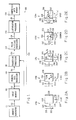
- FIG. 2A shows a flat icon 128a
- Fig. 2B shows an edge icon 128b
- Fig. 2C shows a ribbon icon 128c
- Fig. 2d shows a corner icon 128d
- Fig. 2E shows a spot icon 128e.
- the icons 128 are shown with the principal axes parallel to the axis of the block of data pixels.
- a vertical axis 210 is shown to the left of each block with an arrow pointing downward and having a positive amplitude direction indicated by an arrow 212 orthogonal thereto and a horizontal axis 214 is shown underneath each block of pixels with an arrow pointing rightward and having a positive amplitude direction indicated by an arrow 216 orthogonal thereto.
- the projection of intensity transitions onto the orthogonal axes 210,214 is represented by dashed lines between the block 230 and the projected pulse signal 234 in Fig. 2B.
- the principal axis processor 114 determines the angle ⁇ between the principal axes of the intensity distribution in the block of pixels 230 and the axes of the block of pixels 230 as one of the attributes of the icon 128 and as the axis of projection by the projection processor 118. Then, the projection is rotated through the ⁇ angle so that it is performed along the principal axes. 210,214
- the flat icon 128a (Fig. 2A) is matched to a block of pixels 230 that has no discernible structure or that is roughly uniform or specular in intensity distribution.
- the flat icon 128a does not have any edges and hence projects onto the two flat projected pulse signals 222,224.
- the edge icon 128b (Fig. 2B) is matched to the block of pixels 230 whose dominant structure is a single step transition in intensity.
- the edge icon 128b has a single edge 236 which projects onto a single transition projected pulse signal 234 and onto a flat projected pulse signal 232.
- the ribbon icon 128c (Fig. 2A) is matched to a block of pixels 230 that has no discernible structure or that is roughly uniform or specular in intensity distribution.
- the flat icon 128a does not have any edges and hence projects onto the two flat projected pulse signals 222,224.
- the edge icon 128b (Fig. 2B) is matched to the block of pixels 230 whose dominant structure is a single step transition in intensity.
- the ribbon icon 128c has two edges 246-247 which project onto a double transition projected pulse signal 244 and onto a flat projected pulse signal 242.
- the corner icon 128d (Fig. 2D) is matched to a block of pixels 230 whose dominant structure consists of two orthogonally intersecting step transitions.
- the comer icon 128d has three edges 256-258 where the single edge 258 projects onto a single transition projected pulse signal 252 and where the pair of double edges 256-257 project onto a double transition projected pulse signal 254.
- the spot icon 128e (Fig.
- the spot icon 128e has four edges 266- 269 where the first pair of double edges 268-269 project onto a double transition projected pulse signal 262 and where the second pair of double edges 266-267 project onto a double transition projected pulse signal 264.
- Orthogonal icons 128 have important advantages, particularly in data compressing of images having manufactured objects, such as a vehicle or a structure, in contrast to natural objects, such as a hill or a tree.
- the set of orthogonal icons 128 shown in Figs. 2A-2E have combinations of a flat ideal pulse signal having no transitions, a single transition ideal pulse signal, and a double transition ideal pulse signal.
- the CLASSIFICATION MATRIX having all possible combinations of these three ideal pulse signal types is presented below.
- FIG. 3 Details regarding processing of a block of pixels in accordance with the principles of the present invention is shown in Fig. 3.
- a 10 by 10 block of pixels for example, having an intensity pattern, illustrated by the darkness of the pixel squares in the block, is projected along the principal axes 311,312 that are rotated by an angle ⁇ to be aligned with the intensity pattern of the block.
- the pixels are shown arrayed in rows A to J and columns 0 to 9.
- a pixel is identified by the row and column designation.
- the angle of the principal axis ⁇ is calculated from moment of inertia equations used in the mechanics art.
- the rectangular block is clipped to a circular block to enhance boundary symmetry.
- f(x,y) is the mass per unit area at location (x,y).
- f(x,y) is the intensity per unit area at location (x,y).
- Projection along the principal axes 311-312 to derive the projected pulse signals 315-316 is performed by the projection processor 118.
- the intensity of each of the pixels in a row, as indicated by the arrows 313, are summed to generated projected points on the pulse signal 315 and the intensity of each of the pixels in a column, as indicated by the arrows 314, are summed to generated projected points on the pulse signal 316.
- each of the ten row pixels A0-A9 are summed to generate the amplitude of the leftmost point or interval on the pulse signal 315
- each of the ten row pixels B0-B9 are summed to generate the amplitude of the next point or interval on the pulse signal 315, and so forth for each of the ten rows A-J, generating the pulse signal 315
- each of the ten column pixels A0-J0 are summed to generate the amplitude of the leftmost point or interval on the pulse signal 316
- each of the ten column pixels A1-J1 are summed to generate the amplitude of the next point on the pulse signal 316, and so forth for each of the ten columns 0-9 generating the pulse signal 316.
- Fitting of the projected pulse signals 315-316 to match the ideal pulse signals is performed by the pulse fitting processor 122.
- the raggedness of the pixel intensities in the block 310 is reflected in the raggedness or steps (solid lines) in the projected pulse signals 315-316.
- Each of the projected pulse signals is associated with the best fit ideal pulse signal in preparation for classification.
- the double stepped projected pulse signal 315 is fitted to a single step ideal pulse signal 318 (dashed lines) and the multiple up and down stepped projected pulse signal 316 is fitted to a flat ideal pulse signal 319 (dashed lines). This is performed with a least squares fit calculation performed in the pulse fitting processor 122.
- Classification of the symbolic icons is performed by the classification processor 126.
- the number of transitions in a best fit pulse signal classifies the pulse signal as either a no transition or flat pulse signal, a single transition pulse signal, or a double transition pulse signal.
- Classification of the block as one of the icon types is performed by a table lockup using the best fit classification of the two projected pulse signals as the input to the CLASSIFICATION MATRIX.
- the matrix points in the CLASSIFICATION MATRIX are defined by the icons in Figs. 2A to 2E with the exception of the center matrix point having two single transition pulse signals. Consistent with the method of classifying all of the block conditions with one of the five icons, this center condition is classified as a corner icon because it is related to a corner icon at the edge of a block.
- the selected attributes include the following.
- the orientation angle attribute ⁇ 116 is obtained from the principal axis processor 114.
- the other attributes are extracted from the projected pulse signals.
- the attribute of the average intensity for a flat icon 128a is calculated by averaging the twenty intensity values of the pair of projected pulse signals 222,224 (Fig. 2A).
- the attributes of the position of the edge 236 in the pulse signal 234, the position of the edges 246-247 in the pulse signal 244, the position of the edges 256-257 in the pulse signal 254, the position of the edge 258 in the pulse signal 252, the position of the edges 266-267 in the pulse signal 264, and the position of the edges 268-269 in the pulse signal 262 are available from the least squares fit performed by the pulse fitting processor 122.
- the width and length attributes are calculated by subtracting the two parallel transitions in the pulse signal 244 (Fig. 2C), the pulse signal 254 (Fig. 2D), and the pulse signals 262 and 264 (Fig. 2E).
- the center position attributes are calculated by averaging the position (one half of the sum of the two transition positions) of the two parallel transitions in the pulse signal 244 (Fig. 2C), the pulse signal 254 (Fig. 2D), and the pulse signals 262 and 264 (Fig. 2E).
- the attribute of the average intensity on each side of the edge is calculated by averaging the intensity values of the pulse signal 234 (Fig. 2B) to the right side of the edge and to the left side of the edge.
- the average background intensity attribute is calculated by averaging the intensity outside the corner, the low part of the pulse signal 252 and the high part of the pulse signal 254 in Fig. 2D), or the intensity outside the spot, the high part of the pulse signal 262 and the low part of the pulse signal 264 in Fig. 2E).
- the average corner or spot intensity attribute is calculated by averaging the intensity inside the corner, the high part of the pulse signal 252 and the low part of the pulse signal 254 in Fig. 2D) or the intensity inside the spot, the low part of the pulse signal 262 and the high part of the pulse signal 264 in Fig. 2E).
- the flat icon has a constant average exterior intensity 228.
- the edge icon 128b has two regions 238,239 of different intensities. The position of the edge is defined by an arrow pointing from the center of the edge X0, Y0 toward the center of the block of pixels.
- the exterior intensity 238 is defined as being in the opposite direction relative to the arrow.
- the interior intensity 239 is defined as being in the same direction as the arrow.
- the ribbon icon 128c has an exterior intensity 245,248 split by a ribbon of interior intensity 249. The position of the ribbon is defined by the coordinates X0, Y0 of the center of the inside edge of the ribbon.
- the width of the ribbon is defined as the length of vector 241 that is normal to the two edges and interposed between the two edges.
- the corner icon 128d has an exterior intensity 258 and has a corner region of interior intensity 259. The position of the corner is defined by the coordinates X0, Y0 of the center of the inside edge 258 of the corner. The width of the corner is defined as the length of vector 251 that is normal to the two edges and interposed between the two edges.
- the spot icon 128e has an exterior intensity 268 and has a spot region of interior intensity 269. The position of the spot is defined by the coordinates X0, Y0 of the center of the spot.
- the width of the spot is defined as the magnitude of the edge 267 and the length of the spot is defined as the magnitude of the edge 268.
- the image memory 110 and the compressed memory 134 may be implemented as different memories.
- the processors 114, 118, 122, and 126 may be partitioned to be in separate processors, in different portions of the same processors.
- the arrangement shown in Fig. 1 may be implemented in parallel processing form, in pipeline processing form, or in parallel pipeline processing form, for example.
- the processors 114, 118, 122, and 126 may be implemented by stored program processors, by special purpose hardwired processors, or in other forms.
- Stored program processors may be implemented by microprocessors, by array processors, by RISC processors, for example.
- the present invention identifies and characterizes selected orthogonal features within a digital image.
- the image is partitioned into small blocks of pixels and then, independent of each other, each block is orthogonally matched to a predefined set of orthogonal icons.
- Each icon and its attributes characterizes the intensity and spatial distribution of an orthogonal feature within the related block. Selection of a particular orthogonal icon and deriving the related attributes constitutes data compression for a block.
- Data compression using orthogonal icons is performed by a sequence of processing operations.
- the principal axis angle is computed for the image intensity data within each block of pixels in order to align the axes with the orthogonal features and thus to reduce a three degree-of-freedom feature in a block to a two degree-of-freedom feature.
- the block is projected along the principal axes to generate two single degree-of-freedom projected pulse signals and thus to reduce a two degree-of-freedom aligned feature to a pair of single degree-of-freedom pulse signals.
- the pair of projected pulse signals associated with the block are each fitted to an ideal pulse signal.
- the pair of ideal pulse signals associated with the block are classified as one of a plurality of orthogonal icons, each having one or more attributes, which reduces the pair of single degree-of-freedom ideal pulse signals to point parameters.
- a three degree-of-freedom feature involving a block of 100 pixels, for example, and hence 100 pixel parameters, is reduced to a point feature having as few as two block parameters.
Landscapes
- Engineering & Computer Science (AREA)
- Multimedia (AREA)
- Signal Processing (AREA)
- Physics & Mathematics (AREA)
- General Physics & Mathematics (AREA)
- Theoretical Computer Science (AREA)
- Image Processing (AREA)
- Compression Of Band Width Or Redundancy In Fax (AREA)
- Compression Or Coding Systems Of Tv Signals (AREA)
- Compression, Expansion, Code Conversion, And Decoders (AREA)
- Image Analysis (AREA)
Applications Claiming Priority (2)
| Application Number | Priority Date | Filing Date | Title |
|---|---|---|---|
| US07/514,778 US5109438A (en) | 1990-04-25 | 1990-04-25 | Data compression system and method |
| US514778 | 1990-04-25 |
Publications (3)
| Publication Number | Publication Date |
|---|---|
| EP0453828A2 true EP0453828A2 (de) | 1991-10-30 |
| EP0453828A3 EP0453828A3 (en) | 1992-08-05 |
| EP0453828B1 EP0453828B1 (de) | 1996-10-09 |
Family
ID=24048657
Family Applications (1)
| Application Number | Title | Priority Date | Filing Date |
|---|---|---|---|
| EP91105251A Expired - Lifetime EP0453828B1 (de) | 1990-04-25 | 1991-04-03 | Verbessertes Datenkomprimierungssystem und -verfahren |
Country Status (13)
| Country | Link |
|---|---|
| US (1) | US5109438A (de) |
| EP (1) | EP0453828B1 (de) |
| JP (1) | JPH04229381A (de) |
| KR (1) | KR950009855B1 (de) |
| AU (1) | AU634373B2 (de) |
| CA (1) | CA2039038C (de) |
| DE (1) | DE69122542T2 (de) |
| EG (1) | EG20205A (de) |
| ES (1) | ES2094766T3 (de) |
| GR (1) | GR3022164T3 (de) |
| IL (1) | IL97724A (de) |
| NO (1) | NO911629L (de) |
| TR (1) | TR26116A (de) |
Cited By (1)
| Publication number | Priority date | Publication date | Assignee | Title |
|---|---|---|---|---|
| DE10041037A1 (de) * | 2000-08-22 | 2002-03-14 | Ubicom Ges Fuer Telekommunikat | Bildkodierungsverfahren und Bildkodierer |
Families Citing this family (19)
| Publication number | Priority date | Publication date | Assignee | Title |
|---|---|---|---|---|
| US5790599A (en) * | 1989-01-19 | 1998-08-04 | Redband Technologies, Inc. | Data compression system using source representation |
| US6185324B1 (en) * | 1989-07-12 | 2001-02-06 | Hitachi, Ltd. | Semiconductor failure analysis system |
| JP2941308B2 (ja) | 1989-07-12 | 1999-08-25 | 株式会社日立製作所 | 検査システムおよび電子デバイスの製造方法 |
| GB9006080D0 (en) * | 1990-03-17 | 1990-05-16 | Int Computers Ltd | Progressive encoding |
| CA2049273A1 (en) * | 1990-10-25 | 1992-04-26 | Cindy E. Daniell | Self adaptive hierarchical target identification and recognition neural network |
| FR2670923A1 (fr) * | 1990-12-21 | 1992-06-26 | Philips Lab Electronique | Dispositif de correlation. |
| IL106335A0 (en) * | 1992-08-03 | 1993-12-28 | Redband Technologies Inc | Data compression system using source representation |
| US5502807A (en) * | 1992-09-21 | 1996-03-26 | Tektronix, Inc. | Configurable video sequence viewing and recording system |
| JPH06113147A (ja) * | 1992-09-29 | 1994-04-22 | Canon Inc | ノイズ除去装置 |
| US5610657A (en) * | 1993-09-14 | 1997-03-11 | Envistech Inc. | Video compression using an iterative error data coding method |
| JPH07170521A (ja) * | 1993-12-15 | 1995-07-04 | Canon Inc | 画像処理装置 |
| US5784284A (en) * | 1995-12-29 | 1998-07-21 | Snap-On Tools Company | Technique for plotting a variable-width signal in a fixed-width plot area |
| US6789070B1 (en) * | 2000-06-14 | 2004-09-07 | The United States Of America As Represented By The Secretary Of The Navy | Automatic feature selection system for data containing missing values |
| CN1533660B (zh) * | 2001-07-20 | 2010-12-22 | Nxp股份有限公司 | 识别可变数据速率的方法与装置 |
| US7454068B2 (en) * | 2003-11-12 | 2008-11-18 | International Business Machines Corporation | System and method for providing black white image compression |
| US7515758B2 (en) * | 2004-02-03 | 2009-04-07 | International Business Machines Corporation | Black white image compression having print density control |
| US20060092147A1 (en) * | 2004-11-03 | 2006-05-04 | Roberts Ben D | Pulse width modulation technique and apparatus for a display array |
| US7830552B2 (en) * | 2005-04-15 | 2010-11-09 | International Business Machines Corporation | Black white image scaling having print density control and polarity detection |
| CN114492136B (zh) * | 2022-01-17 | 2025-03-07 | 中科南京移动通信与计算创新研究院 | 雨衰数据的获取方法、设备和存储介质 |
Family Cites Families (16)
| Publication number | Priority date | Publication date | Assignee | Title |
|---|---|---|---|---|
| US3268864A (en) * | 1963-03-18 | 1966-08-23 | Apparatus for feature recognition of symbols | |
| US3980809A (en) * | 1973-07-16 | 1976-09-14 | International Business Machines Corporation | Encoding logic for reduced bandwidth pictorial data transmission system |
| DE2423817A1 (de) * | 1973-07-16 | 1975-02-06 | Ibm | Verfahren und schaltungsanordnungen zur codierung zweidimensionaler bildinformationen |
| US4281312A (en) * | 1975-11-04 | 1981-07-28 | Massachusetts Institute Of Technology | System to effect digital encoding of an image |
| JPS5929020B2 (ja) * | 1977-06-08 | 1984-07-17 | 松下電器産業株式会社 | 2次元ブロック符号化方法 |
| JPS5484416A (en) * | 1977-12-19 | 1979-07-05 | Ricoh Co Ltd | Meothod and device for transmission and reception of telautogram information |
| US4205341A (en) * | 1978-01-24 | 1980-05-27 | Nippon Telegraph And Telephone Public Corporation | Picture signal coding apparatus |
| US4529228A (en) * | 1980-09-02 | 1985-07-16 | Kramer Henry P | Method and apparatus for coding pictorial information for efficient storage, transmission and reproduction |
| JPS5949071A (ja) * | 1982-09-13 | 1984-03-21 | Dainippon Screen Mfg Co Ltd | 図形輪郭デ−タ圧縮方法 |
| US4553171A (en) * | 1984-01-27 | 1985-11-12 | Xerox Corporation | Tile encoding in image printing |
| JPS61159869A (ja) * | 1985-01-08 | 1986-07-19 | Mitsubishi Electric Corp | ベクトル量子化器 |
| JPS6275782A (ja) * | 1985-09-30 | 1987-04-07 | Canon Inc | 画像符号化装置 |
| JPH0824341B2 (ja) * | 1985-10-28 | 1996-03-06 | 株式会社日立製作所 | 画像データ符号化方法 |
| DE3542484A1 (de) * | 1985-11-30 | 1987-07-02 | Ant Nachrichtentech | Verfahren zur erkennung von kantenstrukturen in einem bildsignal |
| US4947447A (en) * | 1986-04-24 | 1990-08-07 | Hitachi, Ltd. | Method for data coding |
| JPS6349925A (ja) * | 1986-08-20 | 1988-03-02 | Takahiro Haniyu | 高速パタ−ンマツチング用ゲ−トアレ−の構成方法 |
-
1990
- 1990-04-25 US US07/514,778 patent/US5109438A/en not_active Expired - Lifetime
-
1991
- 1991-03-26 CA CA002039038A patent/CA2039038C/en not_active Expired - Lifetime
- 1991-03-28 IL IL9772491A patent/IL97724A/en unknown
- 1991-04-03 DE DE69122542T patent/DE69122542T2/de not_active Expired - Fee Related
- 1991-04-03 EP EP91105251A patent/EP0453828B1/de not_active Expired - Lifetime
- 1991-04-03 ES ES91105251T patent/ES2094766T3/es not_active Expired - Lifetime
- 1991-04-10 AU AU74317/91A patent/AU634373B2/en not_active Ceased
- 1991-04-23 EG EG23491A patent/EG20205A/xx active
- 1991-04-24 NO NO91911629A patent/NO911629L/no unknown
- 1991-04-24 KR KR1019910006607A patent/KR950009855B1/ko not_active Expired - Fee Related
- 1991-04-25 JP JP3095326A patent/JPH04229381A/ja active Pending
- 1991-04-29 TR TR91/0506A patent/TR26116A/xx unknown
-
1996
- 1996-12-27 GR GR960403633T patent/GR3022164T3/el unknown
Cited By (1)
| Publication number | Priority date | Publication date | Assignee | Title |
|---|---|---|---|---|
| DE10041037A1 (de) * | 2000-08-22 | 2002-03-14 | Ubicom Ges Fuer Telekommunikat | Bildkodierungsverfahren und Bildkodierer |
Also Published As
| Publication number | Publication date |
|---|---|
| ES2094766T3 (es) | 1997-02-01 |
| GR3022164T3 (en) | 1997-03-31 |
| EP0453828B1 (de) | 1996-10-09 |
| IL97724A (en) | 1994-10-07 |
| AU7431791A (en) | 1991-11-07 |
| KR910019450A (ko) | 1991-11-30 |
| NO911629L (no) | 1991-10-28 |
| DE69122542T2 (de) | 1997-02-13 |
| EP0453828A3 (en) | 1992-08-05 |
| CA2039038C (en) | 1994-10-25 |
| US5109438A (en) | 1992-04-28 |
| JPH04229381A (ja) | 1992-08-18 |
| NO911629D0 (no) | 1991-04-24 |
| CA2039038A1 (en) | 1991-10-26 |
| EG20205A (en) | 1997-10-30 |
| TR26116A (tr) | 1995-02-15 |
| IL97724A0 (en) | 1992-06-21 |
| DE69122542D1 (de) | 1996-11-14 |
| KR950009855B1 (ko) | 1995-08-29 |
| AU634373B2 (en) | 1993-02-18 |
Similar Documents
| Publication | Publication Date | Title |
|---|---|---|
| EP0453828A2 (de) | Verbessertes Datenkomprimierungssystem und -verfahren | |
| EP0453827B1 (de) | Verbessertes Datenkomprimierungssystem und -verfahren | |
| US10776111B2 (en) | Point cloud data method and apparatus | |
| US5592572A (en) | Automated portrait/landscape mode detection on a binary image | |
| US12380669B2 (en) | Method for cargo counting, computer equipment, and storage medium | |
| Eichmann et al. | Topologically invariant texture descriptors | |
| US6853374B2 (en) | Image space display method and apparatus | |
| EP0633550A2 (de) | Verfahren und Vorrichtung zur Bildverarbeitung | |
| Alexandridis et al. | Picture decomposition, tree data-structures, and identifying directional symmetries as node combinations | |
| US4167729A (en) | Apparatus for obtaining multi-spectral signatures | |
| Vlachos et al. | Graph—theoretical approach to colour picture segmentation and contour classification | |
| EP0380720A1 (de) | Verfahren zur Bildverarbeitung | |
| US7075681B1 (en) | System and method for reducing the data volume of images | |
| EP0460967A1 (de) | Hierarchische Operationen auf Randattributdaten für Bildbereiche | |
| DE69032400T2 (de) | Bilddatenverarbeitungssystem und methode | |
| US4435836A (en) | Technique for extracting features from images | |
| JP3075815B2 (ja) | 画像処理装置 | |
| CA1096504A (en) | Method and apparatus for obtaining multi-spectral signatures | |
| JP2532086B2 (ja) | 画像特徴抽出装置 | |
| Ipatov et al. | Creation of image models for evolving objects on dynamically changing scenes | |
| Ince | Digital image processing systems and remote sensing | |
| KR900009121B1 (ko) | 특징 데이타를 고속으로 분류하는 방법과 그 방법을 실현하기 위한 특징 데이타 처리장치 | |
| Bouridane et al. | A Parallel implementation of a novel cubic interpolation technique for visual analysis | |
| JP2914074B2 (ja) | 限定色決定方法および装置 | |
| Risse | Yet another line parametrization for hough transform |
Legal Events
| Date | Code | Title | Description |
|---|---|---|---|
| PUAI | Public reference made under article 153(3) epc to a published international application that has entered the european phase |
Free format text: ORIGINAL CODE: 0009012 |
|
| AK | Designated contracting states |
Kind code of ref document: A2 Designated state(s): CH DE ES FR GB GR IT LI NL SE |
|
| PUAL | Search report despatched |
Free format text: ORIGINAL CODE: 0009013 |
|
| AK | Designated contracting states |
Kind code of ref document: A3 Designated state(s): CH DE ES FR GB GR IT LI NL SE |
|
| 17P | Request for examination filed |
Effective date: 19930129 |
|
| 17Q | First examination report despatched |
Effective date: 19941221 |
|
| GRAH | Despatch of communication of intention to grant a patent |
Free format text: ORIGINAL CODE: EPIDOS IGRA |
|
| GRAH | Despatch of communication of intention to grant a patent |
Free format text: ORIGINAL CODE: EPIDOS IGRA |
|
| GRAA | (expected) grant |
Free format text: ORIGINAL CODE: 0009210 |
|
| AK | Designated contracting states |
Kind code of ref document: B1 Designated state(s): CH DE ES FR GB GR IT LI NL SE |
|
| REG | Reference to a national code |
Ref country code: CH Ref legal event code: NV Representative=s name: ISLER & PEDRAZZINI AG |
|
| REF | Corresponds to: |
Ref document number: 69122542 Country of ref document: DE Date of ref document: 19961114 |
|
| ET | Fr: translation filed | ||
| ITF | It: translation for a ep patent filed | ||
| REG | Reference to a national code |
Ref country code: ES Ref legal event code: FG2A Ref document number: 2094766 Country of ref document: ES Kind code of ref document: T3 |
|
| REG | Reference to a national code |
Ref country code: GR Ref legal event code: FG4A Free format text: 3022164 |
|
| PGFP | Annual fee paid to national office [announced via postgrant information from national office to epo] |
Ref country code: DE Payment date: 19970321 Year of fee payment: 7 |
|
| PGFP | Annual fee paid to national office [announced via postgrant information from national office to epo] |
Ref country code: CH Payment date: 19970324 Year of fee payment: 7 |
|
| PGFP | Annual fee paid to national office [announced via postgrant information from national office to epo] |
Ref country code: NL Payment date: 19970327 Year of fee payment: 7 |
|
| PGFP | Annual fee paid to national office [announced via postgrant information from national office to epo] |
Ref country code: GR Payment date: 19970328 Year of fee payment: 7 |
|
| PGFP | Annual fee paid to national office [announced via postgrant information from national office to epo] |
Ref country code: ES Payment date: 19970417 Year of fee payment: 7 |
|
| PLBE | No opposition filed within time limit |
Free format text: ORIGINAL CODE: 0009261 |
|
| STAA | Information on the status of an ep patent application or granted ep patent |
Free format text: STATUS: NO OPPOSITION FILED WITHIN TIME LIMIT |
|
| 26N | No opposition filed | ||
| PGFP | Annual fee paid to national office [announced via postgrant information from national office to epo] |
Ref country code: SE Payment date: 19980319 Year of fee payment: 8 |
|
| PG25 | Lapsed in a contracting state [announced via postgrant information from national office to epo] |
Ref country code: ES Free format text: LAPSE BECAUSE OF EXPIRATION OF PROTECTION Effective date: 19980404 |
|
| PG25 | Lapsed in a contracting state [announced via postgrant information from national office to epo] |
Ref country code: GR Free format text: LAPSE BECAUSE OF NON-PAYMENT OF DUE FEES Effective date: 19980430 Ref country code: LI Free format text: LAPSE BECAUSE OF NON-PAYMENT OF DUE FEES Effective date: 19980430 Ref country code: CH Free format text: LAPSE BECAUSE OF NON-PAYMENT OF DUE FEES Effective date: 19980430 |
|
| REG | Reference to a national code |
Ref country code: GB Ref legal event code: 732E |
|
| PG25 | Lapsed in a contracting state [announced via postgrant information from national office to epo] |
Ref country code: NL Free format text: LAPSE BECAUSE OF NON-PAYMENT OF DUE FEES Effective date: 19981101 |
|
| REG | Reference to a national code |
Ref country code: CH Ref legal event code: PL |
|
| NLV4 | Nl: lapsed or anulled due to non-payment of the annual fee |
Effective date: 19981101 |
|
| PG25 | Lapsed in a contracting state [announced via postgrant information from national office to epo] |
Ref country code: DE Free format text: LAPSE BECAUSE OF NON-PAYMENT OF DUE FEES Effective date: 19990202 |
|
| PG25 | Lapsed in a contracting state [announced via postgrant information from national office to epo] |
Ref country code: SE Free format text: LAPSE BECAUSE OF NON-PAYMENT OF DUE FEES Effective date: 19990404 |
|
| EUG | Se: european patent has lapsed |
Ref document number: 91105251.2 |
|
| REG | Reference to a national code |
Ref country code: ES Ref legal event code: FD2A Effective date: 20000301 |
|
| REG | Reference to a national code |
Ref country code: FR Ref legal event code: CD Ref country code: FR Ref legal event code: TP Ref country code: FR Ref legal event code: CA |
|
| REG | Reference to a national code |
Ref country code: GB Ref legal event code: IF02 |
|
| PG25 | Lapsed in a contracting state [announced via postgrant information from national office to epo] |
Ref country code: IT Free format text: LAPSE BECAUSE OF NON-PAYMENT OF DUE FEES;WARNING: LAPSES OF ITALIAN PATENTS WITH EFFECTIVE DATE BEFORE 2007 MAY HAVE OCCURRED AT ANY TIME BEFORE 2007. THE CORRECT EFFECTIVE DATE MAY BE DIFFERENT FROM THE ONE RECORDED. Effective date: 20050403 |
|
| PGFP | Annual fee paid to national office [announced via postgrant information from national office to epo] |
Ref country code: FR Payment date: 20100506 Year of fee payment: 20 |
|
| PGFP | Annual fee paid to national office [announced via postgrant information from national office to epo] |
Ref country code: GB Payment date: 20100420 Year of fee payment: 20 |
|
| REG | Reference to a national code |
Ref country code: GB Ref legal event code: PE20 Expiry date: 20110402 |
|
| PG25 | Lapsed in a contracting state [announced via postgrant information from national office to epo] |
Ref country code: GB Free format text: LAPSE BECAUSE OF EXPIRATION OF PROTECTION Effective date: 20110402 |