EP0453467B1 - Wegwerfeinspritznadel für einmalige verwendung sowie verfahren zur herstellung - Google Patents
Wegwerfeinspritznadel für einmalige verwendung sowie verfahren zur herstellung Download PDFInfo
- Publication number
- EP0453467B1 EP0453467B1 EP90901644A EP90901644A EP0453467B1 EP 0453467 B1 EP0453467 B1 EP 0453467B1 EP 90901644 A EP90901644 A EP 90901644A EP 90901644 A EP90901644 A EP 90901644A EP 0453467 B1 EP0453467 B1 EP 0453467B1
- Authority
- EP
- European Patent Office
- Prior art keywords
- piston
- barrel
- rod
- syringe
- manoeuvring
- Prior art date
- Legal status (The legal status is an assumption and is not a legal conclusion. Google has not performed a legal analysis and makes no representation as to the accuracy of the status listed.)
- Expired - Lifetime
Links
Images


Classifications
-
- A—HUMAN NECESSITIES
- A61—MEDICAL OR VETERINARY SCIENCE; HYGIENE
- A61M—DEVICES FOR INTRODUCING MEDIA INTO, OR ONTO, THE BODY; DEVICES FOR TRANSDUCING BODY MEDIA OR FOR TAKING MEDIA FROM THE BODY; DEVICES FOR PRODUCING OR ENDING SLEEP OR STUPOR
- A61M5/00—Devices for bringing media into the body in a subcutaneous, intra-vascular or intramuscular way; Accessories therefor, e.g. filling or cleaning devices, arm-rests
- A61M5/50—Devices for bringing media into the body in a subcutaneous, intra-vascular or intramuscular way; Accessories therefor, e.g. filling or cleaning devices, arm-rests having means for preventing re-use, or for indicating if defective, used, tampered with or unsterile
- A61M2005/5006—Having means for destroying the syringe barrel, e.g. by cutting or piercing
-
- Y—GENERAL TAGGING OF NEW TECHNOLOGICAL DEVELOPMENTS; GENERAL TAGGING OF CROSS-SECTIONAL TECHNOLOGIES SPANNING OVER SEVERAL SECTIONS OF THE IPC; TECHNICAL SUBJECTS COVERED BY FORMER USPC CROSS-REFERENCE ART COLLECTIONS [XRACs] AND DIGESTS
- Y10—TECHNICAL SUBJECTS COVERED BY FORMER USPC
- Y10S—TECHNICAL SUBJECTS COVERED BY FORMER USPC CROSS-REFERENCE ART COLLECTIONS [XRACs] AND DIGESTS
- Y10S128/00—Surgery
- Y10S128/917—Body fluid, devices for protection therefrom, e.g. aids, hepatitus
- Y10S128/919—Syringe, means to protect user
Definitions
- the subject of the present invention is disposable syringes which cannot be reused after a first injection and methods of manufacturing them.
- Disposable syringes are increasingly being used after use to avoid the risk of contamination in the event of the use of a poorly sterilized syringe after first use.
- the stem of these syringes carries projections which abut one after the other on the end of the reservoir and which are broken along an oblique line of least resistance which leaves a point which lines the wall of the reservoir.
- Such syringes cannot be used as empty syringes allowing a dose of liquid to be drawn up by suction.
- the problem to be solved is to provide self-destructing syringes which can be sold empty and which first allow the piston to be pushed into the reservoir to expel the air without scratching the reservoir and then to withdraw the piston backwards to aspirate a liquid without scratching or cutting the wall of the reservoir and then pushing the piston back into the reservoir to inject the dose of liquid contained therein by cutting or scratching or breaking the wall of the reservoir to render the syringe unusable a second time.
- a syringe according to the invention is of the known type comprising a cylindrical reservoir, a piston displaceable inside said reservoir, an operating rod of said piston and a cutting member which lines or cuts or breaks the wall of said reservoir during injection of the liquid contained in said reservoir.
- the solution of the problem posed consists of a syringe in which one end of the operating rod and said piston are connected by means which allow relative axial displacement and one of the two carries at least one flexible finger, which carries at its end one cutting member is free while the other carries a deflection means which cooperates with said flexible finger to deform the latter by pushing outward said cutting member when said end of the operating rod and said piston approach one on the other so that when the operating rod is withdrawn backwards to fill the syringe with the liquid to be injected, said flexible fingers occupy a position in which said overpowering members are erased inside said reservoir and do not not touch the wall thereof and when said piston is pressed into said reservoir by pushing on the operating rod to inject the liquid said flexible fingers extend cartent and said cutting members are pushed outward and cut or scratch the wall of the reservoir which makes the syringe unusable a second time.
- said piston or a end of the operating rod carries one or more inclined ramps relative to the axis of the syringe against which slide said flexible fingers deviating towards the outside when the operating rod and said piston are axially approaching one of the other and disappearing inwards when the operating rod and said piston move away from one another axially.
- each of the flexible fingers is connected to the piston or to one end of said operating rod by an articulated link which pushes said flexible finger outwards when said piston and said operating rod are brought together axially. on the other and which brings said flexible finger inward when said piston and said operating rod move away from each other axially.
- a method of manufacturing a non-reusable syringe according to the invention comprises the following operations:
- the invention results in new disposable syringes which cannot be reused after a first injection.
- the syringes according to the invention have the advantage of being able be delivered unfilled with the plunger pressed into the syringe reservoir, this operation being carried out in the factory by connecting the syringes to a suction means which draws the plunger towards the bottom of the syringe so that the cutting members are erased during this operation and do not risk scratching or cutting the wall of the tank.
- the syringes according to the invention also have the advantage that the cutting members are pushed back radially by a force which is proportional to the axial thrust exerted on the operating rod during injection so that the penetration of the cutting members into the wall of the reservoir is better assured than in known syringes where the knife is pushed radially by a spring exerting a constant thrust.
- the freedom of axial relative movement of the operating rod relative to the piston of the syringe makes it possible to obtain a spacing of the knives towards the outside when the operating rod is pressed but also a clearing of the knives towards the inside when the operating rod moves axially away from the piston, that is to say when the operating rod is pulled to draw liquid or else when the piston is drawn to push it into the syringe so that at during these two operations, the cutting members are not likely to cut or scratch the wall of the tank.
- Figure 1 shows in axial section a disposable syringe according to a first embodiment.
- FIG. 2 represents in partial axial section the same disposable syringe according to the invention in the cutting position.
- FIG. 3 is a cross section along line III III of FIG. 2.
- Figure 4 shows in axial section a second embodiment of disposable syringes according to the invention.
- FIG. 5 represents, in partial axial section, the same variant embodiment as in FIG. 4, under conditions of use identical to those of FIG. 2.
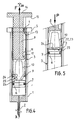
- Figure 6 shows in axial section a third mode of realization of disposable syringes according to the invention.
- FIG. 7 shows in partial axial section the same disposable syringe in the cutting position.
- FIG. 8 represents in partial axial section a fourth embodiment of disposable syringes according to the invention.
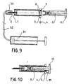
- FIGS 9 and 10 show the implementation of the manufacturing method according to the invention.
- Figures 11, 12 and 13 show three particular embodiments of the cylindrical reservoir of disposable syringes according to the invention.
- Figure 14 is a section along XIV XIV of Figure 11.
- FIG. 15 is a section along XV XV of FIG. 12.
- Figure 16 is a section along XVI XVI of Figure 13.
- a disposable syringe comprises in known manner a cylindrical reservoir 1 of axis XX1 which is provided at one end with a device intended to receive a needle 2 or with an incorporated needle, a rod of maneuver 8 and a piston 6 which slide in said tank.
- Said operating rod typically comprises a groove 11, longitudinal and parallel to the axis, said groove being limited at one end by a disc 15 and at the other end by a stop 12 linked to said operating rod.
- Said reservoir advantageously comprises at one end a flange 5 forming a flange on which is fitted, after positioning of said operating rod in said reservoir, a guide heel 4 which penetrates into said groove.
- Said heel 4 cooperates by its face 13 which forms a stop, with the stop 12 linked to the operating rod, so that when an attempt is made to extract said rod from said reservoir, the stop 12 comes into contact with the stop 13 and therefore prohibits extraction.
- This prohibition prevents the user from removing the cutting elements.
- the wall of said tank comprises at least one zone 3 of least resistance, for example a groove which extends along a generatrix of said cylindrical reservoir substantially over the entire height of said reservoir.
- said piston includes sealing means 7.
- the syringe according to the invention comprises at least one pointed and sharp projection or any other means 9 blunt or cutting or cutting or breaking such as blade, tip or knurl 30 capable of performing grooving, notable and permanent deformation, cutting, perforation or fragmentary rupture of said reservoir so that the latter can no longer cooperate with said piston so as to cause pumping of the fluid, and therefore prevents subsequent use of the syringe for the purpose of injecting said fluid.
- said cutting members are mounted at the free end of flexible fingers 10 which are themselves connected to one or the other of one end of said operating rod or of said piston. .
- the syringe has two flexible fingers.
- said piston comprises at least one deflection surface 16 which is constituted for example by a frustoconical surface as shown in FIGS. 1 and 2, or else by an oblique ramp relative to the XX1 axis, against which the fingers come into contact.
- said deflection surface cooperates with said flexible fingers which occupy a position in which these are erased inside said tank and do not touch the wall thereof.
- said deflection surface cooperates with said flexible fingers to deform them by pushing outward said cutting members when said end of the operating rod and said piston approach each other, following the application of a thrust represented by the arrow P on said operating rod so that said cutting members cut or scratch the wall of said reservoir, which makes the syringe unusable a second time.
- Figures 1 and 2 show that said piston comprises a rod 17 and a bulge 18 which ends in a face 21, that one end of said operating rod comprises a housing 31 limited by a bottom 20, and that said flexible fingers include lugs 19.
- the flexibility of the fingers makes it possible, during assembly of the syringe, to allow the said bulging of the piston to penetrate into the said housing of the operating rod until the said lugs engage behind the said bulging and thus connect the said operating rod and the said piston. such that they retain a freedom of axial relative movement.
- FIG. 2 shows that said axial relative displacement is limited in the direction of approximation between said rod and said piston by the contact of said surface 21 and said bottom 20, so that the spacing of the flexible fingers subsequent to this approximation is thus limit.
- Figure 3 shows that said flexible fingers have bearing faces 22 and 23 located in the immediate vicinity of the cutting members 9, said bearing faces cooperating with the inner wall of said reservoir, thereby limiting the spacing of said cutting members , so that during cutting the cutting members do not protrude outside said tank and cannot injure the user.
- FIGS. 4 and 5 the homologous parts of FIGS. 1 and 2 are represented by the same references.
- FIGS 4 and 5 show another embodiment according to the invention in which said flexible fingers 10 are connected by one end to said operating rod and by the other end to said piston 6 by means of connecting rods 24 articulated at their two ends, the means of connection between said operating rod and said piston thus defined allowing the spacing and erasing of said cutting members corresponding respectively to approximation and to distancing relative of said operating rod and said piston.
- FIGS. 4 and 5 show that said links comprise a substantially rigid central part which itself has a surface 25 which forms an abutment, and two ends of cross section and of rigidity substantially less than the central part, so that said ends of the rod which are linked, for one to said piston, for the other to said flexible finger, can deform and thus constitute a joint.
- FIG. 5 shows that, following the application of a thrust on the operating rod, represented by the arrow P, the forces transmitted by said flexible fingers lead to a deformation of the ends of the rods 24 until the at least one of the stops 22, 23 and 25 produces its effects; this deformation of the ends of the connecting rods causes the cutting members 9 to deflect towards the wall of said tank, so that, when the piston is pressed into said tank, said cutting members cut or scratch said inner wall of said tank.
- FIGS. 6 and 7 show a third embodiment according to the invention.
- the homologous parts of FIGS. 1 and 2 are represented by the same references.
- the piston 6 has a rod 17 and a bulge 18 which can slide in a housing 31 arranged at the end of said operating rod 8 which itself comprises lugs 27 and a bearing face 28 which allows relative axial displacement between the operating rod and the piston.
- At least two deflection surfaces 16 which form two oblique ramps which converge towards one another in the direction of the operating rod.
- a U-shaped elastic pin 38 constitutes a pair of flexible fingers, the ends of which are bent and carry the cutting members 9.
- Said pin is held integral with said operating rod by a connecting means 29 such as pliers, rings or any other equivalent fixing means.
- the deflection surface 16 cooperates with said flexible fingers so that they are erased inside said cylindrical reservoir without touching the wall thereof, when said piston moves away from said rod maneuver.
- FIG. 7 shows that during the injection of the liquid under the action of a push by the user on said operating rod, represented by the arrow P, said deflection surface pushes outwards, due to the approximation of said piston and said operating rod, said cutting members which cut or scratch said wall.
- the deflection surfaces in the form of inclined ramps, can be formed by the bottom of a groove formed in said rod 17, the sides of said groove serving to guide the flexible fingers during the relative movements between said piston and said operating rod.
- FIG. 8 shows an alternative embodiment according to the invention, in which the cutting members are constituted by knobs 30, in particular for the case where said reservoir is made of a brittle material such as glass, plastics of polycarbonate type, which, under the pressure exerted by said knobs according to the same principles as developed for the other embodiments, will undergo a fragmentary rupture or bursting.
- the cutting members are constituted by knobs 30, in particular for the case where said reservoir is made of a brittle material such as glass, plastics of polycarbonate type, which, under the pressure exerted by said knobs according to the same principles as developed for the other embodiments, will undergo a fragmentary rupture or bursting.
- the cylindrical reservoir can be covered externally with a flexible film which forms a jacket preventing the dispersion of the fragments resulting from the rupture.
- the rupture occurs in the zone of least resistance 3 constituted by a groove made in the mass, said groove being filled with a flexible resin which prevents the dispersion of the fragments resulting from the rupture.
- FIG. 9 represents the means used in the process for manufacturing disposable syringes according to the invention, and more particularly in the process which consists in bringing said piston into the bottom of said reservoir without damaging the latter and making it possible to deliver syringes empty and ready to be filled by suction.
- the means comprise at least one pipe 32, equipped with a connection device 33, which device can be fixed on the end of the syringe intended to receive the needles, or directly at the end of the incorporated needle.
- Said pipe is connected to suction means 34 such as a pump for example.
- the four main parts making up the syringe namely said reservoir, said piston, said operating rod, said heel, can be manufactured separately.
- the rod and the piston are integral.
- said piston When said suction means are actuated, said piston is subjected to a force due to the pressure difference existing between its faces, which force causes it to move towards the bottom of said tank; the flexible fingers remain in their erased position during this movement.
- the piston drives the operating rod in its movement.
- said heel 4 is mounted on said flange and place between the collar 5 of the tank and the disc 15 of the end of the operating rod as shown in FIG. 10, a safety spacer 39 in order to avoid in the event of accidental pressing on the operating rod, during the handling, packaging or unpacking of the syringe, this support does not have the effect of cutting or scratching before use the wall of the reservoir, rendering the syringe unusable prematurely.
- Figures 11 to 16 show three other embodiments of a syringe according to the invention in which said reservoir comprises said zone of least resistance 3 which extends along a generatrix of said cylindrical reservoir.
- said wall of said tank has two prominent zones 35 which extend along two generatrices of said tank, on either side of said zone of least resistance 3, and form two beads so that during the cutting of said reservoir by said cutting members, said prominent zones prevent any accidental contact between said cutting members and the user.
- FIGS. 12 and 15 represent another variant in which said wall comprises a single prominent zone, in the form of a tongue 36, which partially covers said zone of least resistance 3.
- FIGS. 13 and 16 represent a variant according to the invention in which said prominent zones 35 situated on either side of said zone 3 meet to form a tongue 37 which entirely covers said zone 3.
- FIGS. 11 to 16 make it possible to avoid any risk of injury to the user by said cutting members.
Landscapes
- Health & Medical Sciences (AREA)
- Vascular Medicine (AREA)
- Engineering & Computer Science (AREA)
- Anesthesiology (AREA)
- Biomedical Technology (AREA)
- Heart & Thoracic Surgery (AREA)
- Hematology (AREA)
- Life Sciences & Earth Sciences (AREA)
- Animal Behavior & Ethology (AREA)
- General Health & Medical Sciences (AREA)
- Public Health (AREA)
- Veterinary Medicine (AREA)
- Infusion, Injection, And Reservoir Apparatuses (AREA)
- Materials For Medical Uses (AREA)
Claims (12)
- Wegwerfspritze zur einmaligen Verwendung, umfassend eine zylindrische Kammer (1), einen innerhalb der besagten Kammer verschiebbaren Kolben (6), einen Betätigungsschaft (8) des besagten Kolbens und eine Schnittvorrichtung (9), die die Wand der besagten Kammer während des Einspritzens der in dieser Kammer enthaltenen Flüssigkeit einritzt oder zerschneidet, dadurch gekennzeichnet, daß ein Ende des besagten Betätigungsschafts und der Kolben durch Vorrichtungen miteinander verbunden sind, die ihre jeweilige Axialbewegung zulassen, wobei einer von beiden mindestens einen beweglichen Finger (10) aufweist, der an seinem freien Ende eine Schnittvorrichtung (9) aufweist, während der andere eine Ablenkvorrichtung (16) aufweist, die mit dem genannten beweglichen Finger zusammen funktioniert, um diesen zu verformen, indem sie die genannte Schnittvorrichtung nach außen drückt, wenn das genannte Ende des Betätigungsschafts und der Kolben aufeinander zulaufen, so daß, wenn man den genannten Kolben in die besagte Kammer drückt, indem man auf den Betätigungsschaft drückt, sich die genannten beweglichen Finger spreizen und die genannten Schnittvorrichtungen die Wand der Kammer zerschneiden oder einritzen, wodurch eine Wiederverwendung der Spritze unmöglich gemacht wird, und, wenn man den Betätigungsschaft zurückzieht, die besagten beweglichen Finger eine Lage einnehmen, in der die besagten Schnittvorrichtungen in das Innere der Kammer eingezogen werden und deren Wand nicht berühren.
- Spritze nach Anspruch 1, dadurch gekennzeichnet, daß der Kolben oder ein Ende des Betätigungsschafts eine oder mehrere bezüglich der Achse der Spritze abgeschrägte Stellen (16) aufweist, gegen die die genannten beweglichen Finger gleiten, wenn sie sich nach außen spreizen, wenn sich Betätigungsschaft und Kolben axial einander annähern, und wenn sie nach innen zurückgehen, wenn der Betätigungsschaft und der Kolben sich axial voneinander entfernen.
- Spritze nach Anspruch 1, dadurch gekennzeichnet, daß entweder der Kolben oder ein Ende des besagten Betätigungsschafts eine konische Fläche aufweisen, die auf die Achse der Spritze zentriert ist, gegen die die genannten beweglichen Finger gleiten, wenn sie sich nach außen spreizen oder nach innen zurückweichen, je nach dem, ob sich der Kolben oder das Ende des Betätigungsschafts einander axial annähern oder voneinander entfernen.
- Spritze nach einem der Ansprüche 1 bis 3, dadurch gekennzeichnet, daß der Kolben durch einen Schaft (17) verlängert ist, der an seinem freien Ende eine Verstärkung (18) aufweist, und daß der Betätigungsschaft Nocken (19, 27) aufweist, die hinter diese Verstärkung fassen und dabei den Betätigungsschaft und den Kolben so verbinden, daß beide eine geringe axiale Bewegungsfreiheit zueinander behalten.
- Spritze nach Anspruch 1, dadurch gekennzeichnet, daß jeder der beweglichen Finger mit dem Kolben oder einem Ende des Betätigungsschafts über ein schwenkbares Zwischenglied (24) verbunden ist, das den besagten beweglichen Finger nach außen drückt, wenn der Kolben und der Betätigungsschaft einander axial annähern, und das den beweglichen Finger nach innen einzieht, wenn der Kolben und der Betätigungsschaft sich axial voneinander entfernen.
- Spritze nach Anspruch 1, bei der die besagte Kammer aus zerbrechlichem Material wie Glas oder Polycarbonat besteht, dadurch gekennzeichnet, daß die Schnittvorrichtungen aus einem Rädchen (30) bestehen, durch dessen Drücken gegen die Innenwand das Brechen der Kammer entlang von Sollbruchstellen erreicht wird.
- Spritze nach Anspruch 1, dadurch gekennzeichnet, daß die Schnittvorrichtungen an einer elastischen Nadel (38) sitzen, die die besagten beweglichen Finger bildet und am Betätigungsschaft befestigt ist.
- Spritze nach den Ansprüchen 1 bis 7, bei der die zylindrische Kammer entlang einer Erzeugenden mindestens eine Sollbruchstelle (3) aufweist, dadurch gekennzeichnet, daß diese Sollbruchstelle (3) von zwei Verdickungen (35) gesäumt ist, die gegenüber der Außenwand der besagten Kammer überstehen.
- Spritze nach den Ansprüchen 1 bis 7, bei der die besagte zylindrische Kammer entlang einer Erzeugenden mindestens eine Sollbruchstelle (3) aufweist, dadurch gekennzeichnet, daß die genannte Stelle (3) zumindest teilweise von einer Zunge (36), (37) bedeckt ist.
- Herstellungsverfahren für eine Wegwerfspritze vom Typ umfassend eine zylindrische Kammer, einen innerhalb der besagten Kammer verschiebbaren Kolben, einen Betätigungsschaft für den besagten Kolben und eine Schnittvorrichtung, die die Wand der besagten Kammer während des Einspritzens der in dieser Kammer enthaltenen Flüssigkeit einritzt oder zerschneidet, dadurch gekennzeichnet, daß ein Ende des besagten Betätigungsschafts und der Kolben durch Vorrichtungen miteinander verbunden werden, die ihre Axialbewegung zueinander in einem geringen Maß zulassen, wobei man jeweils einen von beiden mit mindestens einem beweglichen Finger versieht, der an seinem freien Ende eine Schnittvorrichtung aufweist, während der andere eine Ablenkvorrichtung aufweist, die mit dem genannten beweglichen Finger zusammen funktioniert, um diesen nach außen zu spreizen, wenn der Betätigungsschaft und der Kolben einander axial nähern, und diesem zu ermöglichen, nach innen zu weichen, wenn sich der Kolben und der Betätigungsschaft axial voneinander entfernen.
- Verfahren nach Anspruch 10 zur Herstellung einer Spritze umfassend eine Nadelhalterung oder eine eingearbeitete Nadel, dadurch gekennzeichnet, daß man das Endstück der besagten Spritzen, das die besagte Nadelhalterung oder eingearbeitete Nadel aufweist, mit einer Ansaugvorrichtung (34) verbindet, um den Kolben in die besagte Kammer zu drücken, ohne daß die genannten Schnittvorrichtungen die Kammer einritzen oder zerschneiden.
- Verfahren nach einem der Ansprüche 10 bis 11, dadurch gekennzeichnet, daß man zwischen dem Kragen (5) der Kammer und der Scheibe (15) am Ende des Betätigungsschafts eine Sicherheitssperre (39) vorsieht, damit im Falle eines versehentlichen Drückens auf den Betätigungsschaft während des Transports, Verpackens oder Auspackens dieses Drücken die Wand der Kammer nicht vor der Benutzung einritzt oder zerschneidet und die Spritze vorzeitig unbrauchbar macht.
Applications Claiming Priority (2)
| Application Number | Priority Date | Filing Date | Title |
|---|---|---|---|
| FR8900345 | 1989-01-10 | ||
| FR8900345A FR2643257A1 (fr) | 1989-01-10 | 1989-01-10 | Seringue du type jetable dont la destruction intervient durant la premiere injection |
Publications (2)
| Publication Number | Publication Date |
|---|---|
| EP0453467A1 EP0453467A1 (de) | 1991-10-30 |
| EP0453467B1 true EP0453467B1 (de) | 1993-07-21 |
Family
ID=9377676
Family Applications (1)
| Application Number | Title | Priority Date | Filing Date |
|---|---|---|---|
| EP90901644A Expired - Lifetime EP0453467B1 (de) | 1989-01-10 | 1990-01-05 | Wegwerfeinspritznadel für einmalige verwendung sowie verfahren zur herstellung |
Country Status (14)
| Country | Link |
|---|---|
| US (1) | US5257976A (de) |
| EP (1) | EP0453467B1 (de) |
| JP (1) | JPH04502565A (de) |
| KR (1) | KR910700082A (de) |
| AT (1) | ATE91637T1 (de) |
| BR (1) | BR9007011A (de) |
| CA (1) | CA2045499A1 (de) |
| DE (1) | DE69002322T2 (de) |
| DK (1) | DK0453467T3 (de) |
| ES (1) | ES2044551T3 (de) |
| FR (1) | FR2643257A1 (de) |
| HU (1) | HUT63961A (de) |
| OA (1) | OA09377A (de) |
| WO (1) | WO1990007949A1 (de) |
Families Citing this family (19)
| Publication number | Priority date | Publication date | Assignee | Title |
|---|---|---|---|---|
| HUT63064A (en) * | 1990-07-25 | 1993-07-28 | Gonzalez Antonio Serrano | Single-use syringe |
| DE4034673A1 (de) * | 1990-09-27 | 1992-04-02 | Bader & Partner Medizintechnik | Spritze, insbesondere fuer den medizinischen gebrauch |
| US5215524A (en) * | 1992-07-14 | 1993-06-01 | Vallelunga Anthony J | Plunger for non-reuseable syringe |
| EP0620020A1 (de) * | 1993-04-15 | 1994-10-19 | Sanitor S.L. | Einwegspritze |
| US5352203A (en) * | 1994-03-31 | 1994-10-04 | Vallelunga Anthony J | Aspirating non-reuseable syringe |
| CA2168201A1 (en) * | 1996-01-26 | 1997-07-27 | Douglas C.V. Campbell | Auto-destruct disposable syringe |
| BR9800002C1 (pt) * | 1998-01-09 | 2000-04-25 | Jose Luiz De Paiva Marques | Dispositivo de travamento para seringas descartáveis. |
| WO1999044661A1 (en) * | 1998-03-06 | 1999-09-10 | Paiva Marques Jose Luiz De | Locking and blocking system for descardable or disposable syringe |
| CA2282974A1 (en) * | 1999-09-22 | 2001-03-22 | Douglas C. V. Campbell | Auto-destruct syringe |
| EP1099449A1 (de) * | 1999-11-12 | 2001-05-16 | Schöttli Ag | Verfahren zur Herstellung eines Pumpkolbens für eine Einwegspritze und ein Pumpkolben |
| US6530903B2 (en) | 2000-02-24 | 2003-03-11 | Xiping Wang | Safety syringe |
| US20040186428A1 (en) * | 2002-09-11 | 2004-09-23 | Utpal Ray | Auto-destructible syringe |
| IL157981A (en) | 2003-09-17 | 2014-01-30 | Elcam Medical Agricultural Cooperative Ass Ltd | Auto injector |
| IL160891A0 (en) | 2004-03-16 | 2004-08-31 | Auto-mix needle | |
| US8038656B2 (en) | 2006-09-29 | 2011-10-18 | Tyco Healthcare Group Lp | Detachable plunger rod syringe |
| RU2351368C1 (ru) * | 2007-11-30 | 2009-04-10 | Открытое акционерное общество "Ижевский радиозавод" | Шприц одноразового использования |
| CN104117115B (zh) | 2008-11-26 | 2017-05-24 | 贝克顿·迪金森公司 | 单次使用自动失效注射器 |
| CN113713213B (zh) * | 2021-09-22 | 2023-08-11 | 浙江欧健医用器材有限公司 | 一种整形外科用一次性玻尿酸注射器 |
| CN115300723A (zh) * | 2022-07-31 | 2022-11-08 | 杭州美伊美医疗科技有限公司 | 具有自毁功能的注射器 |
Family Cites Families (16)
| Publication number | Priority date | Publication date | Assignee | Title |
|---|---|---|---|---|
| US3667657A (en) * | 1969-01-02 | 1972-06-06 | Marcelo Chiqular Arias | Disposable container |
| US3951146A (en) * | 1972-11-01 | 1976-04-20 | Arias Marcelo Chiquiar | Disposable self-destructible syringes which render themselves unreusable |
| US3934586A (en) * | 1975-01-22 | 1976-01-27 | Easton Fred H | Non-refillable multiple dosage syringe |
| NO157085C (no) * | 1986-01-07 | 1988-01-20 | Chr Sandsdalen | Anordning ved injeksjonssprte for engangsbruk. |
| US4731068A (en) * | 1987-05-01 | 1988-03-15 | Hesse John E | Non-reloadable syringe |
| IN169618B (de) * | 1987-06-25 | 1991-11-23 | Agven Medical Corp Ltd | |
| AU618238B2 (en) * | 1987-09-18 | 1991-12-19 | Program For Appropriate Technology In Health (Path) | Single use disposable syringe |
| JPH02502073A (ja) * | 1987-11-06 | 1990-07-12 | エルガス・ルイ・パウル | 再使用不能な注射器 |
| WO1989006146A1 (en) * | 1987-12-30 | 1989-07-13 | Jacques Verlier | Non-reusable syringe |
| US4961728A (en) * | 1988-12-30 | 1990-10-09 | Becton, Dickinson And Company | Single-use syringe having misuse resistant features |
| ES2089021T3 (es) * | 1989-08-07 | 1996-10-01 | Alan Chris Allison | Elemento insertable para impedir la reutilizacion de jeringuillas de plastico. |
| US5084017A (en) * | 1989-10-10 | 1992-01-28 | John Maffetone | Self disabling, single use, hypodermic syringe |
| WO1991012039A1 (en) * | 1990-02-15 | 1991-08-22 | Alan Henry Polyblank | Non-reusable syringe |
| US4979943A (en) * | 1990-03-15 | 1990-12-25 | Trenner Lewis E | Single use hypodermic syringe |
| US5085640A (en) * | 1990-04-06 | 1992-02-04 | Gibbs Andrew H | Non-reusable medical needle apparatus |
| US5149323A (en) * | 1991-04-08 | 1992-09-22 | Colonna John P | Self destruct double syringe |
-
1989
- 1989-01-10 FR FR8900345A patent/FR2643257A1/fr active Pending
-
1990
- 1990-01-05 HU HU90941A patent/HUT63961A/hu unknown
- 1990-01-05 KR KR1019900701741A patent/KR910700082A/ko not_active Withdrawn
- 1990-01-05 DK DK90901644.6T patent/DK0453467T3/da active
- 1990-01-05 JP JP2501767A patent/JPH04502565A/ja active Pending
- 1990-01-05 ES ES90901644T patent/ES2044551T3/es not_active Expired - Lifetime
- 1990-01-05 US US07/690,995 patent/US5257976A/en not_active Expired - Fee Related
- 1990-01-05 AT AT90901644T patent/ATE91637T1/de not_active IP Right Cessation
- 1990-01-05 EP EP90901644A patent/EP0453467B1/de not_active Expired - Lifetime
- 1990-01-05 WO PCT/FR1990/000007 patent/WO1990007949A1/fr not_active Ceased
- 1990-01-05 CA CA002045499A patent/CA2045499A1/fr not_active Abandoned
- 1990-01-05 DE DE90901644T patent/DE69002322T2/de not_active Expired - Fee Related
- 1990-01-05 BR BR909007011A patent/BR9007011A/pt not_active Application Discontinuation
-
1991
- 1991-07-20 OA OA60036A patent/OA09377A/xx unknown
Also Published As
| Publication number | Publication date |
|---|---|
| DE69002322D1 (de) | 1993-08-26 |
| US5257976A (en) | 1993-11-02 |
| KR910700082A (ko) | 1991-03-13 |
| HUT63961A (en) | 1993-11-29 |
| DE69002322T2 (de) | 1994-01-20 |
| ATE91637T1 (de) | 1993-08-15 |
| DK0453467T3 (da) | 1993-11-22 |
| CA2045499A1 (fr) | 1990-07-11 |
| BR9007011A (pt) | 1991-11-12 |
| WO1990007949A1 (fr) | 1990-07-26 |
| EP0453467A1 (de) | 1991-10-30 |
| ES2044551T3 (es) | 1994-01-01 |
| JPH04502565A (ja) | 1992-05-14 |
| FR2643257A1 (fr) | 1990-08-24 |
| OA09377A (fr) | 1992-09-15 |
Similar Documents
| Publication | Publication Date | Title |
|---|---|---|
| EP0453467B1 (de) | Wegwerfeinspritznadel für einmalige verwendung sowie verfahren zur herstellung | |
| BE1001078A3 (fr) | Seringue pre-remplie. | |
| CA1247962A (fr) | Ampoule-seringue | |
| EP1027902B1 (de) | Injektionsspritze mit Selbstschutz | |
| EP1329234B1 (de) | Sicherheitsanordnung für Spritze vorgefüllt mit flüssigem Arzneimittel | |
| CH620126A5 (de) | ||
| FR2767479A1 (fr) | Dispositif d'injection de medicament | |
| EP0740942A1 (de) | Verfahren zur Herstellung einer vorgefüllten Injektionsvorrichtung und dadurch erhaltene Injektionsvorrichtung | |
| WO1999039759A1 (fr) | Dispositif d'injection automatique d'une dose de produit medicamenteux | |
| WO2000054723A1 (fr) | Dispositif de transfert bidirectionnel d'un liquide entre un flacon et une carpule | |
| EP2680900A2 (de) | Kanüleneinführer | |
| WO1995021647A1 (fr) | Module injecteur pour une seringue et seringue preremplie equipee de ce module injecteur | |
| EP1330279A1 (de) | Injektionsspritze mit einem verschiebbaren nadelschutz | |
| WO1989000432A2 (fr) | Seringue de haute securite non reutilisable | |
| EP0986411B1 (de) | Perfektionierte injektionsspritze mit ansaugvorrichtung | |
| EP0954345A1 (de) | Injektionsspritze mit einer verschiebbaren nadelschutzvorrichtung | |
| EP2705866A1 (de) | Vorrichtung zur Schmerzreduzierung bei der Einführung einer Spritzennadel in die Haut | |
| FR2900344A1 (fr) | Dispositif d'injection avec aiguille retractable | |
| EP3352821B1 (de) | Ausgabeanordnung mit einer spritze und einem nadelschutz | |
| EP0954347B1 (de) | Injektionsspritze mit einer ins innere des spritzenkörpers hineinragenden nadel | |
| FR2778852A1 (fr) | Seringue d'injection a aiguille retractable | |
| WO2008043895A2 (fr) | Dispositif d'injection a aiguille, pourvu d'un dispositif de condamnation automatique d'aiguille | |
| FR2768930A1 (fr) | Dispositif de protection d'aiguille de seringue a fenetre laterale | |
| FR2543833A1 (fr) | Ensemble non reutilisable pour l'injection d'un produit medicamentaire | |
| FR2805166A1 (fr) | Seringue preemplie a deux pistons mobiles retenant un liquide a injecter |
Legal Events
| Date | Code | Title | Description |
|---|---|---|---|
| PUAI | Public reference made under article 153(3) epc to a published international application that has entered the european phase |
Free format text: ORIGINAL CODE: 0009012 |
|
| 17P | Request for examination filed |
Effective date: 19910613 |
|
| AK | Designated contracting states |
Kind code of ref document: A1 Designated state(s): AT BE CH DE DK ES FR GB IT LI LU NL SE |
|
| 17Q | First examination report despatched |
Effective date: 19921125 |
|
| RAP3 | Party data changed (applicant data changed or rights of an application transferred) |
Owner name: FENET, EMERIC GUY |
|
| GRAA | (expected) grant |
Free format text: ORIGINAL CODE: 0009210 |
|
| AK | Designated contracting states |
Kind code of ref document: B1 Designated state(s): AT BE CH DE DK ES FR GB IT LI LU NL SE |
|
| REF | Corresponds to: |
Ref document number: 91637 Country of ref document: AT Date of ref document: 19930815 Kind code of ref document: T |
|
| REF | Corresponds to: |
Ref document number: 69002322 Country of ref document: DE Date of ref document: 19930826 |
|
| ITF | It: translation for a ep patent filed | ||
| GBT | Gb: translation of ep patent filed (gb section 77(6)(a)/1977) |
Effective date: 19930913 |
|
| REG | Reference to a national code |
Ref country code: DK Ref legal event code: T3 |
|
| REG | Reference to a national code |
Ref country code: ES Ref legal event code: FG2A Ref document number: 2044551 Country of ref document: ES Kind code of ref document: T3 |
|
| EPTA | Lu: last paid annual fee | ||
| PLBE | No opposition filed within time limit |
Free format text: ORIGINAL CODE: 0009261 |
|
| STAA | Information on the status of an ep patent application or granted ep patent |
Free format text: STATUS: NO OPPOSITION FILED WITHIN TIME LIMIT |
|
| 26N | No opposition filed | ||
| EAL | Se: european patent in force in sweden |
Ref document number: 90901644.6 |
|
| PGFP | Annual fee paid to national office [announced via postgrant information from national office to epo] |
Ref country code: NL Payment date: 19951215 Year of fee payment: 7 |
|
| PGFP | Annual fee paid to national office [announced via postgrant information from national office to epo] |
Ref country code: AT Payment date: 19951225 Year of fee payment: 7 |
|
| PGFP | Annual fee paid to national office [announced via postgrant information from national office to epo] |
Ref country code: LU Payment date: 19960101 Year of fee payment: 7 |
|
| PGFP | Annual fee paid to national office [announced via postgrant information from national office to epo] |
Ref country code: GB Payment date: 19960102 Year of fee payment: 7 Ref country code: DK Payment date: 19960102 Year of fee payment: 7 |
|
| PGFP | Annual fee paid to national office [announced via postgrant information from national office to epo] |
Ref country code: SE Payment date: 19960125 Year of fee payment: 7 |
|
| PGFP | Annual fee paid to national office [announced via postgrant information from national office to epo] |
Ref country code: CH Payment date: 19960126 Year of fee payment: 7 |
|
| PGFP | Annual fee paid to national office [announced via postgrant information from national office to epo] |
Ref country code: ES Payment date: 19960130 Year of fee payment: 7 |
|
| PGFP | Annual fee paid to national office [announced via postgrant information from national office to epo] |
Ref country code: BE Payment date: 19960212 Year of fee payment: 7 |
|
| PG25 | Lapsed in a contracting state [announced via postgrant information from national office to epo] |
Ref country code: LU Free format text: LAPSE BECAUSE OF NON-PAYMENT OF DUE FEES Effective date: 19970105 Ref country code: GB Effective date: 19970105 Ref country code: DK Effective date: 19970105 Ref country code: AT Effective date: 19970105 |
|
| REG | Reference to a national code |
Ref country code: DK Ref legal event code: EBP |
|
| PG25 | Lapsed in a contracting state [announced via postgrant information from national office to epo] |
Ref country code: SE Effective date: 19970106 |
|
| PG25 | Lapsed in a contracting state [announced via postgrant information from national office to epo] |
Ref country code: ES Free format text: LAPSE BECAUSE OF NON-PAYMENT OF DUE FEES Effective date: 19970107 |
|
| PGFP | Annual fee paid to national office [announced via postgrant information from national office to epo] |
Ref country code: DE Payment date: 19970121 Year of fee payment: 8 |
|
| PG25 | Lapsed in a contracting state [announced via postgrant information from national office to epo] |
Ref country code: LI Effective date: 19970131 Ref country code: CH Effective date: 19970131 Ref country code: BE Effective date: 19970131 |
|
| BERE | Be: lapsed |
Owner name: FENET EMERIC GUY Effective date: 19970131 |
|
| PG25 | Lapsed in a contracting state [announced via postgrant information from national office to epo] |
Ref country code: NL Effective date: 19970801 |
|
| GBPC | Gb: european patent ceased through non-payment of renewal fee |
Effective date: 19970105 |
|
| REG | Reference to a national code |
Ref country code: CH Ref legal event code: PL |
|
| NLV4 | Nl: lapsed or anulled due to non-payment of the annual fee |
Effective date: 19970801 |
|
| EUG | Se: european patent has lapsed |
Ref document number: 90901644.6 |
|
| PG25 | Lapsed in a contracting state [announced via postgrant information from national office to epo] |
Ref country code: DE Free format text: LAPSE BECAUSE OF NON-PAYMENT OF DUE FEES Effective date: 19981001 |
|
| PGFP | Annual fee paid to national office [announced via postgrant information from national office to epo] |
Ref country code: FR Payment date: 19990129 Year of fee payment: 10 |
|
| REG | Reference to a national code |
Ref country code: ES Ref legal event code: FD2A Effective date: 19990405 |
|
| PG25 | Lapsed in a contracting state [announced via postgrant information from national office to epo] |
Ref country code: FR Free format text: LAPSE BECAUSE OF NON-PAYMENT OF DUE FEES Effective date: 20000929 |
|
| REG | Reference to a national code |
Ref country code: FR Ref legal event code: ST |
|
| PG25 | Lapsed in a contracting state [announced via postgrant information from national office to epo] |
Ref country code: IT Free format text: LAPSE BECAUSE OF NON-PAYMENT OF DUE FEES;WARNING: LAPSES OF ITALIAN PATENTS WITH EFFECTIVE DATE BEFORE 2007 MAY HAVE OCCURRED AT ANY TIME BEFORE 2007. THE CORRECT EFFECTIVE DATE MAY BE DIFFERENT FROM THE ONE RECORDED. Effective date: 20050105 |