EP0453421A2 - Rolling bearing - Google Patents
Rolling bearing Download PDFInfo
- Publication number
- EP0453421A2 EP0453421A2 EP91850048A EP91850048A EP0453421A2 EP 0453421 A2 EP0453421 A2 EP 0453421A2 EP 91850048 A EP91850048 A EP 91850048A EP 91850048 A EP91850048 A EP 91850048A EP 0453421 A2 EP0453421 A2 EP 0453421A2
- Authority
- EP
- European Patent Office
- Prior art keywords
- seal
- spherical
- bearing
- outer ring
- rim
- Prior art date
- Legal status (The legal status is an assumption and is not a legal conclusion. Google has not performed a legal analysis and makes no representation as to the accuracy of the status listed.)
- Granted
Links
Images

Classifications
-
- F—MECHANICAL ENGINEERING; LIGHTING; HEATING; WEAPONS; BLASTING
- F16—ENGINEERING ELEMENTS AND UNITS; GENERAL MEASURES FOR PRODUCING AND MAINTAINING EFFECTIVE FUNCTIONING OF MACHINES OR INSTALLATIONS; THERMAL INSULATION IN GENERAL
- F16C—SHAFTS; FLEXIBLE SHAFTS; ELEMENTS OR CRANKSHAFT MECHANISMS; ROTARY BODIES OTHER THAN GEARING ELEMENTS; BEARINGS
- F16C23/00—Bearings for exclusively rotary movement adjustable for aligning or positioning
- F16C23/06—Ball or roller bearings
- F16C23/08—Ball or roller bearings self-adjusting
- F16C23/082—Ball or roller bearings self-adjusting by means of at least one substantially spherical surface
- F16C23/086—Ball or roller bearings self-adjusting by means of at least one substantially spherical surface forming a track for rolling elements
-
- F—MECHANICAL ENGINEERING; LIGHTING; HEATING; WEAPONS; BLASTING
- F16—ENGINEERING ELEMENTS AND UNITS; GENERAL MEASURES FOR PRODUCING AND MAINTAINING EFFECTIVE FUNCTIONING OF MACHINES OR INSTALLATIONS; THERMAL INSULATION IN GENERAL
- F16C—SHAFTS; FLEXIBLE SHAFTS; ELEMENTS OR CRANKSHAFT MECHANISMS; ROTARY BODIES OTHER THAN GEARING ELEMENTS; BEARINGS
- F16C19/00—Bearings with rolling contact, for exclusively rotary movement
- F16C19/02—Bearings with rolling contact, for exclusively rotary movement with bearing balls essentially of the same size in one or more circular rows
- F16C19/14—Bearings with rolling contact, for exclusively rotary movement with bearing balls essentially of the same size in one or more circular rows for both radial and axial load
- F16C19/18—Bearings with rolling contact, for exclusively rotary movement with bearing balls essentially of the same size in one or more circular rows for both radial and axial load with two or more rows of balls
- F16C19/181—Bearings with rolling contact, for exclusively rotary movement with bearing balls essentially of the same size in one or more circular rows for both radial and axial load with two or more rows of balls with angular contact
- F16C19/183—Bearings with rolling contact, for exclusively rotary movement with bearing balls essentially of the same size in one or more circular rows for both radial and axial load with two or more rows of balls with angular contact with two rows at opposite angles
-
- F—MECHANICAL ENGINEERING; LIGHTING; HEATING; WEAPONS; BLASTING
- F16—ENGINEERING ELEMENTS AND UNITS; GENERAL MEASURES FOR PRODUCING AND MAINTAINING EFFECTIVE FUNCTIONING OF MACHINES OR INSTALLATIONS; THERMAL INSULATION IN GENERAL
- F16C—SHAFTS; FLEXIBLE SHAFTS; ELEMENTS OR CRANKSHAFT MECHANISMS; ROTARY BODIES OTHER THAN GEARING ELEMENTS; BEARINGS
- F16C33/00—Parts of bearings; Special methods for making bearings or parts thereof
- F16C33/72—Sealings
- F16C33/76—Sealings of ball or roller bearings
- F16C33/78—Sealings of ball or roller bearings with a diaphragm, disc, or ring, with or without resilient members
- F16C33/7803—Sealings of ball or roller bearings with a diaphragm, disc, or ring, with or without resilient members suited for particular types of rolling bearings
- F16C33/7806—Sealings of ball or roller bearings with a diaphragm, disc, or ring, with or without resilient members suited for particular types of rolling bearings for spherical roller bearings
-
- F—MECHANICAL ENGINEERING; LIGHTING; HEATING; WEAPONS; BLASTING
- F16—ENGINEERING ELEMENTS AND UNITS; GENERAL MEASURES FOR PRODUCING AND MAINTAINING EFFECTIVE FUNCTIONING OF MACHINES OR INSTALLATIONS; THERMAL INSULATION IN GENERAL
- F16C—SHAFTS; FLEXIBLE SHAFTS; ELEMENTS OR CRANKSHAFT MECHANISMS; ROTARY BODIES OTHER THAN GEARING ELEMENTS; BEARINGS
- F16C33/00—Parts of bearings; Special methods for making bearings or parts thereof
- F16C33/72—Sealings
- F16C33/76—Sealings of ball or roller bearings
- F16C33/78—Sealings of ball or roller bearings with a diaphragm, disc, or ring, with or without resilient members
- F16C33/7816—Details of the sealing or parts thereof, e.g. geometry, material
- F16C33/783—Details of the sealing or parts thereof, e.g. geometry, material of the mounting region
-
- F—MECHANICAL ENGINEERING; LIGHTING; HEATING; WEAPONS; BLASTING
- F16—ENGINEERING ELEMENTS AND UNITS; GENERAL MEASURES FOR PRODUCING AND MAINTAINING EFFECTIVE FUNCTIONING OF MACHINES OR INSTALLATIONS; THERMAL INSULATION IN GENERAL
- F16C—SHAFTS; FLEXIBLE SHAFTS; ELEMENTS OR CRANKSHAFT MECHANISMS; ROTARY BODIES OTHER THAN GEARING ELEMENTS; BEARINGS
- F16C33/00—Parts of bearings; Special methods for making bearings or parts thereof
- F16C33/72—Sealings
- F16C33/76—Sealings of ball or roller bearings
- F16C33/78—Sealings of ball or roller bearings with a diaphragm, disc, or ring, with or without resilient members
- F16C33/784—Sealings of ball or roller bearings with a diaphragm, disc, or ring, with or without resilient members mounted to a groove in the inner surface of the outer race and extending toward the inner race
- F16C33/7843—Sealings of ball or roller bearings with a diaphragm, disc, or ring, with or without resilient members mounted to a groove in the inner surface of the outer race and extending toward the inner race with a single annular sealing disc
- F16C33/7853—Sealings of ball or roller bearings with a diaphragm, disc, or ring, with or without resilient members mounted to a groove in the inner surface of the outer race and extending toward the inner race with a single annular sealing disc with one or more sealing lips to contact the inner race
- F16C33/7856—Sealings of ball or roller bearings with a diaphragm, disc, or ring, with or without resilient members mounted to a groove in the inner surface of the outer race and extending toward the inner race with a single annular sealing disc with one or more sealing lips to contact the inner race with a single sealing lip
-
- F—MECHANICAL ENGINEERING; LIGHTING; HEATING; WEAPONS; BLASTING
- F16—ENGINEERING ELEMENTS AND UNITS; GENERAL MEASURES FOR PRODUCING AND MAINTAINING EFFECTIVE FUNCTIONING OF MACHINES OR INSTALLATIONS; THERMAL INSULATION IN GENERAL
- F16C—SHAFTS; FLEXIBLE SHAFTS; ELEMENTS OR CRANKSHAFT MECHANISMS; ROTARY BODIES OTHER THAN GEARING ELEMENTS; BEARINGS
- F16C33/00—Parts of bearings; Special methods for making bearings or parts thereof
- F16C33/72—Sealings
- F16C33/76—Sealings of ball or roller bearings
- F16C33/78—Sealings of ball or roller bearings with a diaphragm, disc, or ring, with or without resilient members
- F16C33/7886—Sealings of ball or roller bearings with a diaphragm, disc, or ring, with or without resilient members mounted outside the gap between the inner and outer races, e.g. sealing rings mounted to an end face or outer surface of a race
Definitions
- the present invention refers to sealed spherical rolling bearings comprising both ball bearings and roller bearings.
- Spherical bearings in general are not sealed, since they mostly are mounted in some form of a bearing housing, whereby its sufficient that the passage of the shaft through the housing wall is sealed.
- sealed spherical bearings are commonly known.
- a problem with sealing of spherical bearings is that the sealing action of the sealings are affected by the tilting of the bearing.
- the sealing on one side can be pressed harder against a contact surface while the sealing on the other side might have a too loose contact depending on the degree of tilt. That a seal is pressed too hard against a corresponding contact surface naturally does not degrade the sealing action in itself, but an unnecessary high and not desirable friction occurs.
- Special designs of the sealings for spherical bearings therefore have been developed, which withstand tilting of the bearing without increased friction or degraded sealing action.
- the sealings in spherical bearings in general are mounted to the outer ring, either in a groove on the side surface of the outer ring or in a groove at the inner surface of the outer ring beside the spherical running path. If the groove is positioned on the side surface of the outer ring, the seal will mostly lie outside the bearing and a problem will arise when the bearing is mounted, since the side wall is occupied by the seal. At the mounting of the bearing one has to consider that there has to be a space for the seal on the outside of the bearing. This is however not a greater problem.
- the problems have been solved with previously known sealed spherical rolling bearings and provided such a bearing comprising an outer ring with spherical running path, inner ring and between the rings situated roller elements and seals on one or both sides which are characterized in that the seal(s) are designed with a rim which can be snapped in to the spherical running path and clamped in the outer ring by means of this rim and a portion which clamps towards the side plane of the outer ring.
- the seal in one piece of plastic, rubber or sheet metal which at its radial inner rim can be bent inwards against the bearing and there form a labyrinth seal against a surface on the inner ring.
- the seal also can be made in plastic or sheet metal at the radially outer part and let the radially inner part consist of a lip of rubber or similar soft material, which is intended to contact a surface on the inner ring.
- the seal can extend only partly towards the inner ring, on which a lip of soft material is mounted, which contacts the outside of the seal.
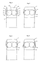
- Fig. 1 in section shows a sealed double row spherical ball bearing of conventional type and where the Figures 2, 3, 4, 5, 6, 7, 8 and 9 show different embodiments of sealed spherical bearings according to the present invention.
- the sealed spherical bearing according to Fig. 1 comprises an outer ring 1, an inner ring 2, balls 3, a retainer 4 and seals 5 on each side of the balls 3.
- the seals 5, which consist of an inner sheet, on which is vulcanized rubber with a sealing lip 6, are pressed into grooves 7 in the outer ring.
- the part of the bearing, which is outside the running paths constitutes a very large part of the width of the bearing, about a fourth, which parts do not contribute to the load carrying capacity of the bearing. If therefore the sealings were not needed, a much narrower bearing could be used with the same load carrying capacity. On one hand one should be able to save material and on the other machining costs, which are large, especially what concerns the turning of the grooves 7.
- a sealed bearing which has the same width as an unsealed bearing should have had and where no grooves for seals have to be done. It has been realized that there normally beside the the roller elements in unsealed bearings there is a small space for seals outside the bearing. These seals however are not allowed to come too far radially outwards on the outer ring and has to be fixed in this near the spherical inside thereof. The reason for this is that it should be possible to lock the outer ring with a step, washers or the like, which engages the side plane of the ring.
- the seals 8 which have been provided with a rim 9 with the inside thereof near the radially outer part of the seal, which rim 9 is intended to be snapped in against the spherical race track 10 of the bearing.
- this at the outer part 11 is formed such that it presses against the side plane 12 of the outer ring. In this way the seal is kept in a secure grip.
- a condition that the mounting of the seal should be possible is that the rim 9 is somewhat elastic. It is therefore suitable if the whole outer part of the seal 8 or only the rim is made of an elastic material such as stiff rubber, plastic or metal sheet.
- a further advantage with the rim 9 is that it is clamped by the balls when the bearing is tilted, so that the seal 8 is not pressed out of the bearing. Otherwise such an incident may easily occur during the handling of the bearing before the assembly.
- the whole seal 8 can be made in one and the same material and it may, such as is shown in Fig. 2, have a radially inner part 13, which is bent inwards against the inner ring 2 and there forms a labyrinth seal against the inner ring.
- Fig. 3 shows the same type of bearing as Fig. 2.
- the seal 8 in this case is made of two materials, namely plastic in the outer part and with an inner part 13 of rubber or similar soft material, which is formed as a sealing lip, which gives frictional contact with the inner ring 2.
- Fig. 4 shows the same bearing and seal as Fig. 3 but with a differently designed inner sealing lip 14.
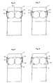
- Fig. 5 shows a further embodiment of the invention applied on the same type of bearing as in the preceding figures.
- a seal 8 is made in one piece, which extends only partly down towards the inner ring 2, on which a sealing lip is mounted, which makes contact against the outside of the seal 8.
- FIGS. 6, 7, 8 and 9 show embodiments corresponding to the embodiments according to Fig. 2-5 respectively with the difference that the seal is made in sheet metal instead of plastic.
- the rim 9 which is intended to be snapped in against the running path 10 has been provided by bending of the sheet. As to the rest the seals according to these figures similar to those according to Fig. 2-5.
Landscapes
- Engineering & Computer Science (AREA)
- General Engineering & Computer Science (AREA)
- Mechanical Engineering (AREA)
- Sealing Of Bearings (AREA)
- Sealing With Elastic Sealing Lips (AREA)
- Rolling Contact Bearings (AREA)
- Support Of The Bearing (AREA)
Abstract
Description
- The present invention refers to sealed spherical rolling bearings comprising both ball bearings and roller bearings.
- Spherical bearings in general are not sealed, since they mostly are mounted in some form of a bearing housing, whereby its sufficient that the passage of the shaft through the housing wall is sealed. However, sealed spherical bearings are commonly known. A problem with sealing of spherical bearings is that the sealing action of the sealings are affected by the tilting of the bearing. The sealing on one side can be pressed harder against a contact surface while the sealing on the other side might have a too loose contact depending on the degree of tilt. That a seal is pressed too hard against a corresponding contact surface naturally does not degrade the sealing action in itself, but an unnecessary high and not desirable friction occurs. The contact becoming too loose naturally degrades the sealing action itself. Special designs of the sealings for spherical bearings therefore have been developed, which withstand tilting of the bearing without increased friction or degraded sealing action.
- The sealings in spherical bearings in general are mounted to the outer ring, either in a groove on the side surface of the outer ring or in a groove at the inner surface of the outer ring beside the spherical running path. If the groove is positioned on the side surface of the outer ring, the seal will mostly lie outside the bearing and a problem will arise when the bearing is mounted, since the side wall is occupied by the seal. At the mounting of the bearing one has to consider that there has to be a space for the seal on the outside of the bearing. This is however not a greater problem.
- When there is no space to let the seal be mounted outside the bearing, this has to be placed as related above, in a groove in eg. the outer ring. The bearing rings however will be much broader than what should be needed for the sake of carrying capacity, since there has to be space inside the bearing beside the roller elements for the sealings.
- By the present invention the problems have been solved with previously known sealed spherical rolling bearings and provided such a bearing comprising an outer ring with spherical running path, inner ring and between the rings situated roller elements and seals on one or both sides which are characterized in that the seal(s) are designed with a rim which can be snapped in to the spherical running path and clamped in the outer ring by means of this rim and a portion which clamps towards the side plane of the outer ring.
- According to the invention it is suitable to make the seal in one piece of plastic, rubber or sheet metal which at its radial inner rim can be bent inwards against the bearing and there form a labyrinth seal against a surface on the inner ring.
- According to the invention the seal also can be made in plastic or sheet metal at the radially outer part and let the radially inner part consist of a lip of rubber or similar soft material, which is intended to contact a surface on the inner ring.
- According to a further embodiment of the invention the seal can extend only partly towards the inner ring, on which a lip of soft material is mounted, which contacts the outside of the seal.
- The invention will be described in greater detail in the following with reference to the figures, where Fig. 1 in section shows a sealed double row spherical ball bearing of conventional type and where the Figures 2, 3, 4, 5, 6, 7, 8 and 9 show different embodiments of sealed spherical bearings according to the present invention.
- The sealed spherical bearing according to Fig. 1 comprises an outer ring 1, an
inner ring 2,balls 3, aretainer 4 andseals 5 on each side of theballs 3. Theseals 5, which consist of an inner sheet, on which is vulcanized rubber with a sealinglip 6, are pressed intogrooves 7 in the outer ring. As is evident from the figure, the part of the bearing, which is outside the running paths, constitutes a very large part of the width of the bearing, about a fourth, which parts do not contribute to the load carrying capacity of the bearing. If therefore the sealings were not needed, a much narrower bearing could be used with the same load carrying capacity. On one hand one should be able to save material and on the other machining costs, which are large, especially what concerns the turning of thegrooves 7. - According to the invention as is shown in there has been provided a sealed bearing which has the same width as an unsealed bearing should have had and where no grooves for seals have to be done. It has been realized that there normally beside the the roller elements in unsealed bearings there is a small space for seals outside the bearing. These seals however are not allowed to come too far radially outwards on the outer ring and has to be fixed in this near the spherical inside thereof. The reason for this is that it should be possible to lock the outer ring with a step, washers or the like, which engages the side plane of the ring.
- Therefore according to the invention there has been provided the
seals 8, which have been provided with arim 9 with the inside thereof near the radially outer part of the seal, whichrim 9 is intended to be snapped in against thespherical race track 10 of the bearing. In order to get the seal securely clamped, this at theouter part 11 is formed such that it presses against theside plane 12 of the outer ring. In this way the seal is kept in a secure grip. A condition that the mounting of the seal should be possible is that therim 9 is somewhat elastic. It is therefore suitable if the whole outer part of theseal 8 or only the rim is made of an elastic material such as stiff rubber, plastic or metal sheet. A further advantage with therim 9 is that it is clamped by the balls when the bearing is tilted, so that theseal 8 is not pressed out of the bearing. Otherwise such an incident may easily occur during the handling of the bearing before the assembly. Thewhole seal 8 can be made in one and the same material and it may, such as is shown in Fig. 2, have a radiallyinner part 13, which is bent inwards against theinner ring 2 and there forms a labyrinth seal against the inner ring. - Fig. 3 shows the same type of bearing as Fig. 2. The
seal 8 in this case is made of two materials, namely plastic in the outer part and with aninner part 13 of rubber or similar soft material, which is formed as a sealing lip, which gives frictional contact with theinner ring 2. - Fig. 4 shows the same bearing and seal as Fig. 3 but with a differently designed
inner sealing lip 14. - Fig. 5 shows a further embodiment of the invention applied on the same type of bearing as in the preceding figures. In this case a
seal 8 is made in one piece, which extends only partly down towards theinner ring 2, on which a sealing lip is mounted, which makes contact against the outside of theseal 8. - The Figures 6, 7, 8 and 9 show embodiments corresponding to the embodiments according to Fig. 2-5 respectively with the difference that the seal is made in sheet metal instead of plastic. The
rim 9 which is intended to be snapped in against the runningpath 10 has been provided by bending of the sheet. As to the rest the seals according to these figures similar to those according to Fig. 2-5. - Through the present invention has been achieved a sealed spherical bearing which can be used with the same external dimensions as an unsealed spherical bearing. Thereby has been achieved a less expensive design, since a sealed bearing according to known designs had to be broader than those according to the invention and are more expensive in manufacture by the turning of a groove for mounting of the seal.
- The invention is not limited to the embodiments shown, but can be varied in different ways within the scope of the patent claims.
Claims (4)
- Spherical rolling bearing comprising an outer ring (1) with a spherical race track (10), inner ring (2) and between the rings (1,2) situated roller elements (3) and seals (8) characterized therein, that the seal(s) (8) are formed with a rim (9) which can be snapped against the spherical race track (10) and kept in the outer ring (1) by means of this rim (9) and a portion (11) which clamps against the side plane (12) of the outer ring (1).
- Spherical rolling bearing according to claim 1, characterized therein, that the seal (8) is made in one piece of plastic, rubber or sheet metal and at its radial inner rim (13) is bent inwards against the bearing and there forms a labyrinth seal against a surface on the inner ring (2).
- Spherical rolling bearing according to claim 1, characterized therein, that the seal (8) consisting of plastic or sheet metal at its radial outer part at its inner portion (4) is provided with a lip (14) of rubber or similar soft material, which is intended to contact a surface on the inner ring (2).
- Spherical rolling bearing according to claim 1, characterized therein, that the seal (8) extends only partly inwards against the inner ring (2) and that a lip (15) mounted on the inner ring (2) of soft material contacts the outside of the seal (8).
Applications Claiming Priority (2)
| Application Number | Priority Date | Filing Date | Title |
|---|---|---|---|
| SE9001373 | 1990-04-18 | ||
| SE9001373A SE464258B (en) | 1990-04-18 | 1990-04-18 | TAETAT SPHERICAL ROLLING STOCK |
Publications (3)
| Publication Number | Publication Date |
|---|---|
| EP0453421A2 true EP0453421A2 (en) | 1991-10-23 |
| EP0453421A3 EP0453421A3 (en) | 1992-04-15 |
| EP0453421B1 EP0453421B1 (en) | 1994-07-27 |
Family
ID=20379196
Family Applications (1)
| Application Number | Title | Priority Date | Filing Date |
|---|---|---|---|
| EP91850048A Expired - Lifetime EP0453421B1 (en) | 1990-04-18 | 1991-02-27 | Rolling bearing |
Country Status (5)
| Country | Link |
|---|---|
| US (1) | US5119446A (en) |
| EP (1) | EP0453421B1 (en) |
| JP (1) | JP2557032B2 (en) |
| DE (1) | DE69103071T2 (en) |
| SE (1) | SE464258B (en) |
Cited By (3)
| Publication number | Priority date | Publication date | Assignee | Title |
|---|---|---|---|---|
| WO2006019347A1 (en) * | 2004-08-19 | 2006-02-23 | Aktiebolaget Skf | A sealed bearing |
| EP2518357A4 (en) * | 2011-02-24 | 2014-04-30 | Nsk Ltd | Double-row angular ball bearing |
| CN106321627A (en) * | 2016-09-14 | 2017-01-11 | 航天精工股份有限公司 | Rod end self-aligning ball bearing |
Families Citing this family (12)
| Publication number | Priority date | Publication date | Assignee | Title |
|---|---|---|---|---|
| SE507561C2 (en) * | 1993-10-11 | 1998-06-22 | Skf Ab | Sealed layer |
| US5580176A (en) * | 1995-09-01 | 1996-12-03 | Federal-Mogul Corporation | Sealing assembly for clutch release bearing |
| SE509420C2 (en) * | 1995-11-09 | 1999-01-25 | Skf Ab | Sealed layer |
| US7031106B2 (en) * | 2000-02-01 | 2006-04-18 | Nsk Ltd. | Sealing member, rolling bearing, thin motor, and bearing device |
| FR2921016B1 (en) * | 2007-09-19 | 2009-12-18 | Skf Ab | SUSPENSION STOPPER DEVICE AND FORCE LEG |
| FR2936033B1 (en) * | 2008-09-16 | 2011-06-10 | Skf Ab | BEARING BEARING, ITS USE AND MOTOR VEHICLE EQUIPPED WITH SUCH A BEARING. |
| US8061903B2 (en) * | 2010-01-28 | 2011-11-22 | Rexnord Industries, Llc | Bearing assembly with extended maintenance interval |
| DE102010019442A1 (en) * | 2010-05-05 | 2011-11-10 | Schaeffler Technologies Gmbh & Co. Kg | Rolling bearing with integrated seal |
| US8740464B2 (en) | 2011-11-02 | 2014-06-03 | Rexnord Industries, Llc | Bearing assembly having a floating seal |
| EP2844886B1 (en) * | 2012-04-30 | 2018-11-07 | Roller Bearing Company of America, Inc. | Hybrid bearing assembly with rolling elements and plain bearing |
| DE102017116875A1 (en) * | 2017-07-26 | 2019-01-31 | Thyssenkrupp Ag | Combination of a roller bearing and at least one cover element and roller mill |
| CN108626242A (en) * | 2018-07-16 | 2018-10-09 | 洛阳Lyc轴承有限公司 | A kind of self-aligning roller bearing of double-sided tape sealing |
Family Cites Families (9)
| Publication number | Priority date | Publication date | Assignee | Title |
|---|---|---|---|---|
| DE8018794U1 (en) * | 1980-10-16 | Fichtel & Sachs Ag, 8720 Schweinfurt | Contact seal for roller bearings | |
| GB693222A (en) * | 1949-07-09 | 1953-06-24 | Charles Henry Whittle | Improvements in and relating to sealing devices for bearings |
| US2919942A (en) * | 1955-10-24 | 1960-01-05 | Gen Dynamics Corp | Bearing construction |
| DE6904329U (en) * | 1969-02-05 | 1969-06-26 | Fichtel & Sachs Ag | SEAL FOR ROLLER BEARING |
| US3858950A (en) * | 1973-02-26 | 1975-01-07 | Timken Co | Sealed bearing |
| US4007933A (en) * | 1975-10-20 | 1977-02-15 | Ideal Toy Corporation | Timing game |
| JPS58214017A (en) * | 1982-05-06 | 1983-12-13 | エス・カ−・エフ・ク−ゲルラ−ゲルフアブリケン・ゲ−エムベ−ハ− | Auxiliary seal for bearing bush |
| DE3838824C2 (en) * | 1988-11-17 | 1995-06-08 | Kugelfischer G Schaefer & Co | Seal consisting of several sealing rings |
| US4872770A (en) * | 1989-04-20 | 1989-10-10 | The Torrington Company | Antifriction bearing with seal arrangement |
-
1990
- 1990-04-18 SE SE9001373A patent/SE464258B/en not_active IP Right Cessation
-
1991
- 1991-02-27 DE DE69103071T patent/DE69103071T2/en not_active Expired - Fee Related
- 1991-02-27 EP EP91850048A patent/EP0453421B1/en not_active Expired - Lifetime
- 1991-03-19 JP JP3078313A patent/JP2557032B2/en not_active Expired - Fee Related
- 1991-04-11 US US07/684,031 patent/US5119446A/en not_active Expired - Lifetime
Cited By (5)
| Publication number | Priority date | Publication date | Assignee | Title |
|---|---|---|---|---|
| WO2006019347A1 (en) * | 2004-08-19 | 2006-02-23 | Aktiebolaget Skf | A sealed bearing |
| CN100513813C (en) * | 2004-08-19 | 2009-07-15 | Skf公司 | sealed bearing |
| EP2518357A4 (en) * | 2011-02-24 | 2014-04-30 | Nsk Ltd | Double-row angular ball bearing |
| US9151324B2 (en) | 2011-02-24 | 2015-10-06 | Nsk Ltd. | Double-row angular ball bearing |
| CN106321627A (en) * | 2016-09-14 | 2017-01-11 | 航天精工股份有限公司 | Rod end self-aligning ball bearing |
Also Published As
| Publication number | Publication date |
|---|---|
| SE464258B (en) | 1991-03-25 |
| DE69103071T2 (en) | 1994-12-01 |
| DE69103071D1 (en) | 1994-09-01 |
| EP0453421A3 (en) | 1992-04-15 |
| SE9001373D0 (en) | 1990-04-18 |
| JP2557032B2 (en) | 1996-11-27 |
| JPH0599234A (en) | 1993-04-20 |
| US5119446A (en) | 1992-06-02 |
| EP0453421B1 (en) | 1994-07-27 |
Similar Documents
| Publication | Publication Date | Title |
|---|---|---|
| EP0453421B1 (en) | Rolling bearing | |
| US4399998A (en) | Self-venting seal lip | |
| EP1058792B1 (en) | Bearing seals | |
| EP0304160B1 (en) | Seal assembly | |
| EP0303359B1 (en) | Seal | |
| EP0228847B1 (en) | Improvements in and relating to seals | |
| US4505484A (en) | Sealing device for a rolling bearing | |
| US5024449A (en) | Seal assembly for use with an overhang | |
| US4755067A (en) | Seal for spherical rolling bearings | |
| CN102439324B (en) | A bearing seal assembly, particularly for use in agricultural applications | |
| US3951482A (en) | Unitized thrust bearing and seal assembly | |
| US5908248A (en) | Shaft bearing having improved seal arrangement | |
| US5372230A (en) | Belt conveyor roller | |
| US20040062461A1 (en) | Roller bearing having high performance bearing seal and cartridge | |
| US4040683A (en) | Hub bearing unit | |
| JPS58124825A (en) | Assembled body of sealed thrust bearing | |
| CA2245725A1 (en) | A bearing for slanted surfaces | |
| US4597582A (en) | Flocked fiber seal for rolling bearings | |
| JPH0133689B2 (en) | ||
| US4664538A (en) | Sealed bearing assembly | |
| US6913264B2 (en) | Sealing arrangement | |
| JPH07127650A (en) | Sealing device of bearing | |
| US4149760A (en) | Snap cage of synthetic material | |
| JPS5936735Y2 (en) | Rolling bearing sealing device | |
| JPH0697055B2 (en) | Multiple seal type rolling bearing |
Legal Events
| Date | Code | Title | Description |
|---|---|---|---|
| PUAI | Public reference made under article 153(3) epc to a published international application that has entered the european phase |
Free format text: ORIGINAL CODE: 0009012 |
|
| AK | Designated contracting states |
Kind code of ref document: A2 Designated state(s): DE FR GB IT |
|
| PUAL | Search report despatched |
Free format text: ORIGINAL CODE: 0009013 |
|
| AK | Designated contracting states |
Kind code of ref document: A3 Designated state(s): DE FR GB IT |
|
| 17P | Request for examination filed |
Effective date: 19920514 |
|
| 17Q | First examination report despatched |
Effective date: 19931222 |
|
| GRAA | (expected) grant |
Free format text: ORIGINAL CODE: 0009210 |
|
| AK | Designated contracting states |
Kind code of ref document: B1 Designated state(s): DE FR GB IT |
|
| ET | Fr: translation filed | ||
| REF | Corresponds to: |
Ref document number: 69103071 Country of ref document: DE Date of ref document: 19940901 |
|
| ITF | It: translation for a ep patent filed | ||
| PLBE | No opposition filed within time limit |
Free format text: ORIGINAL CODE: 0009261 |
|
| STAA | Information on the status of an ep patent application or granted ep patent |
Free format text: STATUS: NO OPPOSITION FILED WITHIN TIME LIMIT |
|
| 26N | No opposition filed | ||
| REG | Reference to a national code |
Ref country code: GB Ref legal event code: IF02 |
|
| PGFP | Annual fee paid to national office [announced via postgrant information from national office to epo] |
Ref country code: FR Payment date: 20030131 Year of fee payment: 13 |
|
| PGFP | Annual fee paid to national office [announced via postgrant information from national office to epo] |
Ref country code: GB Payment date: 20030219 Year of fee payment: 13 |
|
| PG25 | Lapsed in a contracting state [announced via postgrant information from national office to epo] |
Ref country code: GB Free format text: LAPSE BECAUSE OF NON-PAYMENT OF DUE FEES Effective date: 20040227 |
|
| GBPC | Gb: european patent ceased through non-payment of renewal fee | ||
| PG25 | Lapsed in a contracting state [announced via postgrant information from national office to epo] |
Ref country code: FR Free format text: LAPSE BECAUSE OF NON-PAYMENT OF DUE FEES Effective date: 20041029 |
|
| REG | Reference to a national code |
Ref country code: FR Ref legal event code: ST |
|
| PGFP | Annual fee paid to national office [announced via postgrant information from national office to epo] |
Ref country code: DE Payment date: 20050331 Year of fee payment: 15 |
|
| PGFP | Annual fee paid to national office [announced via postgrant information from national office to epo] |
Ref country code: IT Payment date: 20060228 Year of fee payment: 16 |
|
| PG25 | Lapsed in a contracting state [announced via postgrant information from national office to epo] |
Ref country code: DE Free format text: LAPSE BECAUSE OF NON-PAYMENT OF DUE FEES Effective date: 20060901 |
|
| PG25 | Lapsed in a contracting state [announced via postgrant information from national office to epo] |
Ref country code: IT Free format text: LAPSE BECAUSE OF NON-PAYMENT OF DUE FEES Effective date: 20070227 |