EP0453413A1 - Distention device for treating contractures of the paravertebral muscles - Google Patents
Distention device for treating contractures of the paravertebral muscles Download PDFInfo
- Publication number
- EP0453413A1 EP0453413A1 EP91830128A EP91830128A EP0453413A1 EP 0453413 A1 EP0453413 A1 EP 0453413A1 EP 91830128 A EP91830128 A EP 91830128A EP 91830128 A EP91830128 A EP 91830128A EP 0453413 A1 EP0453413 A1 EP 0453413A1
- Authority
- EP
- European Patent Office
- Prior art keywords
- adhesive
- strips
- distension device
- vertical
- horizontal
- Prior art date
- Legal status (The legal status is an assumption and is not a legal conclusion. Google has not performed a legal analysis and makes no representation as to the accuracy of the status listed.)
- Granted
Links
Images

Classifications
-
- A—HUMAN NECESSITIES
- A61—MEDICAL OR VETERINARY SCIENCE; HYGIENE
- A61F—FILTERS IMPLANTABLE INTO BLOOD VESSELS; PROSTHESES; DEVICES PROVIDING PATENCY TO, OR PREVENTING COLLAPSING OF, TUBULAR STRUCTURES OF THE BODY, e.g. STENTS; ORTHOPAEDIC, NURSING OR CONTRACEPTIVE DEVICES; FOMENTATION; TREATMENT OR PROTECTION OF EYES OR EARS; BANDAGES, DRESSINGS OR ABSORBENT PADS; FIRST-AID KITS
- A61F13/00—Bandages or dressings; Absorbent pads
- A61F13/14—Bandages or dressings; Absorbent pads specially adapted for the breast or abdomen
- A61F13/143—Thorax bandages or bandaging garments
-
- A—HUMAN NECESSITIES
- A61—MEDICAL OR VETERINARY SCIENCE; HYGIENE
- A61F—FILTERS IMPLANTABLE INTO BLOOD VESSELS; PROSTHESES; DEVICES PROVIDING PATENCY TO, OR PREVENTING COLLAPSING OF, TUBULAR STRUCTURES OF THE BODY, e.g. STENTS; ORTHOPAEDIC, NURSING OR CONTRACEPTIVE DEVICES; FOMENTATION; TREATMENT OR PROTECTION OF EYES OR EARS; BANDAGES, DRESSINGS OR ABSORBENT PADS; FIRST-AID KITS
- A61F13/00—Bandages or dressings; Absorbent pads
- A61F13/02—Adhesive plasters or dressings
- A61F13/023—Adhesive plasters or dressings wound covering film layers without a fluid handling layer
-
- A—HUMAN NECESSITIES
- A61—MEDICAL OR VETERINARY SCIENCE; HYGIENE
- A61F—FILTERS IMPLANTABLE INTO BLOOD VESSELS; PROSTHESES; DEVICES PROVIDING PATENCY TO, OR PREVENTING COLLAPSING OF, TUBULAR STRUCTURES OF THE BODY, e.g. STENTS; ORTHOPAEDIC, NURSING OR CONTRACEPTIVE DEVICES; FOMENTATION; TREATMENT OR PROTECTION OF EYES OR EARS; BANDAGES, DRESSINGS OR ABSORBENT PADS; FIRST-AID KITS
- A61F5/00—Orthopaedic methods or devices for non-surgical treatment of bones or joints; Nursing devices; Anti-rape devices
- A61F5/01—Orthopaedic devices, e.g. splints, casts or braces
- A61F5/02—Orthopaedic corsets
- A61F5/028—Braces for providing support to the lower back, e.g. lumbo sacral supports
Definitions
- the present invention relates to a distension device for the treatment of contractures of the paravertebral muscles.
- the paravertebral muscles have the function of supporting the spine and allowing its inflection, extension and other movements.
- certain pathological tables which relate to the spinal structures such as discopathies, laxity of the intervertebral joints, ligamentous inflammations and others, one quite often arrives at a blockage of the spinal structures with the analgesic contracture of the paravertebral muscles, which generates analgesic scoliosis so the spine bends permanently on one side and the patient is no longer able to straighten.
- the analgesic contracture can cause pain which can be greater than that due to the cause which caused it and causes, with this one, a vicious circle of aggravation.
- the present invention aims to provide a device for distension of paravertebral muscle contractures, particularly suitable for the treatment of the acute phase of low back pain and sciatica pain tables.
- a distension device comprising at least two parallel horizontal strips of adhesive tape, connected to each other by means of at least two vertical parallel strips of the same adhesive tape: said vertical strips being intended to adhere to the patient's back, on both sides with respect to the spinous processes and in correspondence with the contracted paravertebral musculature situated below and said horizontal bands being intended to ensure the correct attachment of the device to the patient's trunk .
- the adhesive face of the strips which is intended to adhere to the patient's skin, is protected by a sheet of silicone-based paper which must be removed before applying the distension device.
- the advantages obtained thanks to the present invention essentially consist in the fact that it is possible to obtain a relaxation of the paravertebral musculature with an immediate improvement in the painful symptomatology; that a distension device according to the invention is easy to make, simple and quick to apply even by paramedical personnel; that it is practical to carry, easily tolerated by patients of any age and physical constitution, and presents, in addition, no contraindication.
- FIG. 1 shows the overall axonometric view of a muscle distension device according to a first embodiment of the invention, before its use
- FIG. 2 shows a distension device according to another embodiment of the invention
- FIG. 3 shows a detailed view of the distension device of FIG. 1
- FIG. 4 shows the distension device of FIG. 1 after its application on the erector muscle area of the spine
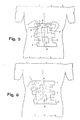
- FIG. 5 illustrates the start of the procedure for applying the distension device to the patient's back
- FIG. 6 illustrates the rest of the procedure for the application of the distension device.
- a distension device for the treatment of contracture of the paravertebral muscles in accordance with the invention consists of three first horizontal parallel strips 1 of adhesive tape, of sufficient width (for example 40-50 mm) and with a length of about 20-25 cm, which are linked together in pairs, but in a single piece, by means of two vertical parallel strips 2 of the same adhesive tape, of the same width as the first strips and d '' a length of around 4-6 cm so as to obtain between each pair of horizontal bands 1 a middle zone 3 devoid of adhesive fabric of about 2-3 cm x 5-6 cm and that the horizontal bands 1 have both ends which protrude on either side with respect to the two vertical bands 2 of about 3-5 cm. All the strips 1,2 are obtained in a single piece by cutting with a cookie cutter, in a piece of anelastic fabric with a self-adhesive face, such as that used for the adhesive plasters.
- the coplanarity between the horizontal bands 1 and the vertical bands 2 of the distension device makes manual application very simple and fixing on the patient's back very effective.
- the dorsal side that is to say the non-adhesive side of the device
- a plate 5 made of plastic or of adhesive felt which is attached superimposed on the rear face of the piece of fabric, before cutting it with a cookie cutter.
- this sheet 4 of silicone-based paper which protects the adhesive face of the strips 1, 2 and to be removed at the time of application of the distension device, this sheet preferably consists of two longitudinal or transverse sections , and this is all the more advantageous as the length of the strips 1,2 is greater.
- the two vertical bands 2 may prove useful, in order to allow a more effective vertical relaxing action, for the two vertical bands 2 to be connected to each other by two horizontal bands 1 and only in correspondence of the upper and lower ends, so as to leave a single central zone 3 deprived of adhesive fabric.
- the horizontal strips 1 are superimposed on the vertical strips 2 on either side of the adhesive face of the latter and united by sewing.
- the result is that the contracted paravertebral muscles, which lie below the two vertical adhesive strips 2, are energetically pulled in the opposite direction to that of the contracture, that is to say downward, to a variable duration between a few hours and a few days and therefore for a period of time sufficient for their relaxation.
- the vertical adhesive strips 2 can be more than two, that is to say four or six, but in any case, the two strips which are in the center must be provided at a distance such that it allows their application on each side of the spinous processes.
Abstract
Description
La présente invention a pour objet un dispositif de distension pour le traitement des contractures des muscles paravertébraux.The present invention relates to a distension device for the treatment of contractures of the paravertebral muscles.
Il est connu que les muscles paravertébraux ont pour fonction de soutenir la colonne vertébrale et de permettre son inflexion, son extension et les autres mouvements. Dans certains tableaux pathologiques qui concernent les structures rachidiennes comme les discopathies, la laxité des articulations intervertébrales, les inflammations ligamenteuses et autres, on arrive assez souvent à un blocage des structures rachidiennes avec la contracture antalgique des muscles paravertébraux, qui engendre une scoliose antalgique de sorte que le rachis se courbe de manière permanente sur un côté et que le patient n'est plus en mesure de se redresser.
Et la contracture antalgique peut provoquer une douleur qui peut être supérieure à celle due à la cause qui l'a engendré et provoque, avec celle-ci, un cercle vicieux d'aggravation.It is known that the paravertebral muscles have the function of supporting the spine and allowing its inflection, extension and other movements. In certain pathological tables which relate to the spinal structures such as discopathies, laxity of the intervertebral joints, ligamentous inflammations and others, one quite often arrives at a blockage of the spinal structures with the analgesic contracture of the paravertebral muscles, which generates analgesic scoliosis so the spine bends permanently on one side and the patient is no longer able to straighten.
And the analgesic contracture can cause pain which can be greater than that due to the cause which caused it and causes, with this one, a vicious circle of aggravation.
Il est bien connu qu'en effectuant une distension de la musculature contracturée, on peut, dans de nombreux cas, résoudre la symptomatologie clinique et, dans d'autres cas, permettre l'exécution de traitements physiothérapiques spécifiques ou la manipulation vertébrale ou l'application du corset, interventions qui sont difficilement supportables pendant la phase aigue.It is well known that by performing a distension of the contracted musculature, one can, in many cases, resolve the clinical symptomatology and, in other cases, allow the execution of specific physiotherapeutic treatments or vertebral manipulation or the application of the brace, interventions which are difficult to bear during the acute phase.
La présente invention a pour but de proposer un dispositif de distension des contractures musculaires paravertébrales, particulièrement adapté pour le traitement de la phase aigue de tableaux de lombalgie et sciatalgie.The present invention aims to provide a device for distension of paravertebral muscle contractures, particularly suitable for the treatment of the acute phase of low back pain and sciatica pain tables.
Ce résultat a été atteint conformément à l'invention en réalisant un dispositif de distension comprenant au moins deux bandes parallèles horizontales de ruban adhésif, reliées entre elles au moyen d'au moins deux bandes parallèles verticales du même ruban adhésif: lesdites bandes verticales étant destinées à adhérer sur le dos du patient, de part et d'autre par rapport aux apophyses épineuses et en correspondance de la musculature paravertébrale contracturée située au-dessous et lesdites bandes horizontales étant destinées à assurer l'accrochage correct du dispositif sur le tronc du patient.This result has been achieved in accordance with the invention by producing a distension device comprising at least two parallel horizontal strips of adhesive tape, connected to each other by means of at least two vertical parallel strips of the same adhesive tape: said vertical strips being intended to adhere to the patient's back, on both sides with respect to the spinous processes and in correspondence with the contracted paravertebral musculature situated below and said horizontal bands being intended to ensure the correct attachment of the device to the patient's trunk .
Avantageusement, la face adhésive des bandes, qui est destinée à adhérer sur la peau du patient, est protégée par une feuille de papier à base de silicone qui doit être retirée avant l'application du dispositif de distension.Advantageously, the adhesive face of the strips, which is intended to adhere to the patient's skin, is protected by a sheet of silicone-based paper which must be removed before applying the distension device.
Les avantages obtenus grâce à la présente invention consistent essentiellement dans le fait qu'il est possible d'obtenir un délassement de la musculature paravertébrale avec une amélioration immédiate de la symptomatologie douloureuse; qu'un dispositif de distension selon l'invention est de réalisation facile, d'application simple et rapide même par le personnel paramédical; qu'il est pratique à porter, facilement tolérable par des patients de n'importe quels âge et constitution physique, et ne présente, en plus, aucune contre-indication.The advantages obtained thanks to the present invention essentially consist in the fact that it is possible to obtain a relaxation of the paravertebral musculature with an immediate improvement in the painful symptomatology; that a distension device according to the invention is easy to make, simple and quick to apply even by paramedical personnel; that it is practical to carry, easily tolerated by patients of any age and physical constitution, and presents, in addition, no contraindication.
Ces avantages et caractéristiques de l'invention ainsi que d'autres seront plus et mieux compris de chaque homme du métier à la lumière de la description qui va suivre et à l'aide des dessins annexés donnés à titre d'exemplification pratique de l'invention, mais à ne pas considérer dans le sens limitatif; dessins sur lesquels la FIG. 1 représente la vue axonométrique d'ensemble d'un dispositif de distension musculaire selon une première forme de réalisation de l'invention, avant son utilisation; la FIG. 2 représente un dispositif de distension selon une autre forme de réalisation de l'invention; la FIG. 3 représente une vue détaillée du dispositif de distension de la Fig. 1; la FIG. 4 représente le dispositif de distension de la Fig. 1 après son application sur la zone du muscle érecteur de la colonne vertébrale; la FIG. 5 illustre le début de la procédure d'application du dispositif de distension sur le dos du patient; la FIG. 6 illustre la suite de la procédure pour l'application du dispositif de distension.These advantages and characteristics of the invention as well as others will be more and better understood by each person skilled in the art in the light of the description which will follow and with the aid of the appended drawings given by way of practical example of the invention, but not to be considered in the limiting sense; drawings in which FIG. 1 shows the overall axonometric view of a muscle distension device according to a first embodiment of the invention, before its use; FIG. 2 shows a distension device according to another embodiment of the invention; FIG. 3 shows a detailed view of the distension device of FIG. 1; FIG. 4 shows the distension device of FIG. 1 after its application on the erector muscle area of the spine; FIG. 5 illustrates the start of the procedure for applying the distension device to the patient's back; FIG. 6 illustrates the rest of the procedure for the application of the distension device.
Réduit à sa structure essentielle et en référence aux Fig. 1 et 3 des dessins annexés, un dispositif de distension pour le traitement de la contracture des muscles paravertébraux conformément à l'invention est constitué de trois premières bandes 1 parallèles horizontales de ruban adhésif, de largeur suffisante (par exemple 40-50 mm) et d'une longueur d'environ 20-25 cm, qui sont reliées entre elles deux à deux, mais en formant un morceau unique, au moyen de deux bandes parallèles verticales 2 du même ruban adhésif, de même largeur que les premières bandes et d'une longueur d'envrion 4-6 cm de manière à obtenir entre chaque paire de bandes horizontales 1 une zone médiane 3 dépourvue de tissu adhésif d'environ 2-3 cm x 5-6 cm et que les bandes horizontales 1 présentent les deux extrémités qui dépassent de part et d'autre par rapport aux deux bandes verticales 2 d'environ 3-5 cm.
Toutes les bandes 1,2 sont obtenues dans un seul morceau par découpage avec emporte-pièce, dans une pièce de tissu anélastique avec une face auto-adhésive, tel que celui utilisé pour les sparadraps.Reduced to its essential structure and with reference to Figs. 1 and 3 of the accompanying drawings, a distension device for the treatment of contracture of the paravertebral muscles in accordance with the invention consists of three first horizontal
All the
Afin d'accroître la robustesse du dispositif de distension, il est prévu, conformément à l'invention, d'utiliser plusieurs tissus anélastiques, auto-adhésifs superposés puis découpés à l'emporte-pièce.In order to increase the robustness of the distension device, it is planned, in accordance with the invention, to use several anelastic, self-adhesive fabrics superimposed and then cut with a cookie cutter.
La coplanarité entre les bandes horizontales 1 et celles verticales 2 du dispositif de distension rend l'application manuelle très simple et la fixation sur le dos du patient très efficace.The coplanarity between the
Pour augmenter la rigidité du dispositif de distension, il est prévu, conformément à l'invention, de munir la face dorsale, c'est-à-dire non adhésive du dispositif, d'une plaque 5 en matière plastique ou en feutre adhésif qui est fixée superposée à la face postérieure du morceau de tissu, avant son découpage par emporte-pièce.To increase the rigidity of the distension device, provision is made, in accordance with the invention, to provide the dorsal side, that is to say the non-adhesive side of the device, with a
Pour ce qui concerne la feuille 4 de papier à base de silicone, qui protège la face adhésive des bandes 1,2 et à enlever au moment de l'application du dispositif de distension, cette feuille est constituée de préférence de deux sections longitudinales ou transversales, et ceci est d'autant plus avantageux que la longueur des bandes 1,2 est plus grande.As regards the
Dans certains cas particuliers, il peut s'avérer utile, dans le but de permettre une action relaxante verticale plus efficace, que les deux bandes verticales 2 soient reliées entre elles par deux bandes horizontales 1 et uniquement en correspondance des extrémités, supérieure et inférieure, de manière à laisser une seule zone médiane 3 privée de tissu adhésif.In certain particular cases, it may prove useful, in order to allow a more effective vertical relaxing action, for the two
En référence à la Fig. 2 des dessins annexés, les bandes horizontales 1 sont superposées à celles verticales 2 de part et d'autre de la face adhésive de ces dernières et unies par couture.With reference to FIG. 2 of the accompanying drawings, the
Pour appliquer le dispositif de distension, procéder de la mamière suivante.
Après avoir détaché le segment de papier à base de silicone 4 correspondant à la bande adhésive horizontale 1 supérieure, on fixe ladite bande sur le dos du patient en correspondance de la zone de passage dorso-lombaire, avec une manoeuvre de pression transversale à effectuer avec un pouce ou avec les deux pouces (voir Fig. 5); ensuite, après avoir libéré la partie supérieure d'une des bandes adhésives verticales 2 du papier à base de silicone correspondant 4, on applique ladite partie de bande 2 avec une opération combinée de pression et de traction vers le bas à effectuer avec le pouce de la main droite, alors qu'on appuie avec la main gauche sur la bande horizontale 1 supérieure, appliquée précédemment (voir Fig. 6); successivement, de la même manière, on applique la partie correspondante de l'autre bande verticale 2; après quoi, on accroche la bande adhésive horizontale 1 médiane; ensuite, on applique la partie inférieure de chacune des bandes adhésives verticales 2 suivant la même technique de compression et de traction vers le bas; et en dernier, on applique la bande adhésive horizontale 1 inférieure.To apply the distension device, proceed as follows.
After having detached the silicone-based
Avec ledit dispositif de distension musculaire ainsi appliqué, on a comme résultat que les muscles paravertébraux contracturés, qui se trouvent en dessous des deux bandes adhésives verticales 2, sont énergiquement tirés dans la direction opposée à celle de la contracture, c'est-à-dire vers le bas, pour une durée variable entre quelques heures et quelques jours et donc pour une période de temps suffisante pour leur décontraction.With said muscle distension device thus applied, the result is that the contracted paravertebral muscles, which lie below the two vertical
Il va de soi que les bandes adhésives verticales 2 peuvent être plus de deux, c'est-à-dire quatre ou six, mais dans tous les cas, les deux bandes qui se trouvent au centre doivent être prévues à une distance telle qu'elle permette leur application de chaque côté des apophyses épineuses.It goes without saying that the vertical
Claims (8)
Applications Claiming Priority (4)
| Application Number | Priority Date | Filing Date | Title |
|---|---|---|---|
| IT936290 | 1990-04-10 | ||
| IT9362A IT1238707B (en) | 1990-04-10 | 1990-04-10 | Adhesive dressing for treating back muscle complaints |
| IT9499A IT1241802B (en) | 1990-10-04 | 1990-10-04 | Improved distention device for the treatment of contractures of the paravertebral muscles. |
| IT949990 | 1990-10-04 |
Publications (2)
| Publication Number | Publication Date |
|---|---|
| EP0453413A1 true EP0453413A1 (en) | 1991-10-23 |
| EP0453413B1 EP0453413B1 (en) | 1994-11-30 |
Family
ID=26326190
Family Applications (1)
| Application Number | Title | Priority Date | Filing Date |
|---|---|---|---|
| EP91830128A Expired - Lifetime EP0453413B1 (en) | 1990-04-10 | 1991-03-28 | Distention device for treating contractures of the paravertebral muscles |
Country Status (4)
| Country | Link |
|---|---|
| US (1) | US5228458A (en) |
| EP (1) | EP0453413B1 (en) |
| AT (1) | ATE114448T1 (en) |
| DE (1) | DE69105339T2 (en) |
Cited By (3)
| Publication number | Priority date | Publication date | Assignee | Title |
|---|---|---|---|---|
| WO1999063919A1 (en) * | 1998-06-09 | 1999-12-16 | Beiersdorf Ag | Self-adhesive bandage |
| FR2838957A1 (en) * | 2002-04-25 | 2003-10-31 | Rene Pierre Requena | Lumbar spine posture controller comprises X-shaped strap with adhesive panels over end rings that pull on the skin when risky positions are adopted |
| FR3116714A1 (en) * | 2020-12-01 | 2022-06-03 | Millet Innovation | DEVICE TO PREVENT AND RELIEVE RACHIALGIA |
Families Citing this family (9)
| Publication number | Priority date | Publication date | Assignee | Title |
|---|---|---|---|---|
| US6749579B1 (en) | 2002-08-07 | 2004-06-15 | Mitchell J. Schroder | Traction garment |
| US6971995B2 (en) * | 2003-01-27 | 2005-12-06 | Michael Alan Rolnick | Method for splinting rib injuries |
| CN101378710A (en) * | 2005-12-23 | 2009-03-04 | 瑞恩·约瑟夫·肯德里克 | Adhesive posture supports |
| US20070299380A1 (en) * | 2006-06-26 | 2007-12-27 | Salivonchik Serges J | Posture aiding method and apparatus |
| CA2578927C (en) * | 2007-02-19 | 2011-09-27 | Ray Arbesman | Precut adhesive body support articles and support system |
| US20160242950A1 (en) * | 2015-02-19 | 2016-08-25 | Cory Jess Chase | Shoulder support apparatus and methods for using same |
| US10342692B2 (en) * | 2016-04-20 | 2019-07-09 | Kevin Pallone | Spine support device for maintaining anatomical alignment and stability |
| USD804679S1 (en) * | 2016-06-30 | 2017-12-05 | Kinesio Ip Llc | Set of adhesive tapes |
| USD796052S1 (en) * | 2016-07-11 | 2017-08-29 | Kinesio Ip Llc | Adhesive tape |
Citations (5)
| Publication number | Priority date | Publication date | Assignee | Title |
|---|---|---|---|---|
| FR928389A (en) * | 1946-05-23 | 1947-11-26 | Device for therapeutic, surgical or beauty treatment | |
| US3068860A (en) * | 1960-08-12 | 1962-12-18 | Strazdas Ernest Alfons | Back plasters |
| US3528426A (en) * | 1967-01-10 | 1970-09-15 | Radivoje Vukojevic | Adhesive band for replacing cutaneous stitching |
| EP0247012A2 (en) * | 1986-05-15 | 1987-11-25 | Roland Andersson | Bandage |
| GB2215607A (en) * | 1988-03-25 | 1989-09-27 | Shyamendu Bhattacherjee | Spinal traction device |
Family Cites Families (12)
| Publication number | Priority date | Publication date | Assignee | Title |
|---|---|---|---|---|
| US2733712A (en) * | 1956-02-07 | Orthopedic belt | ||
| US1785831A (en) * | 1928-03-22 | 1930-12-23 | Marjorie C Edmundson | Surgical bandage |
| GB372145A (en) * | 1931-06-29 | 1932-05-05 | Aimee Sabatier Bion | Improvements in or relating to orthopaedic appliances |
| US2513771A (en) * | 1948-12-09 | 1950-07-04 | Carl T Williams | Incision closer |
| US2541487A (en) * | 1949-12-15 | 1951-02-13 | George H Triplett | Spinal brace |
| US2730096A (en) * | 1952-11-29 | 1956-01-10 | Surgical Appliance Ind | Back brace |
| US3989039A (en) * | 1974-08-22 | 1976-11-02 | Lora Tunney | Facial muscle compressor |
| AU5774186A (en) * | 1985-04-18 | 1986-11-05 | Halldis Aalvik Thune | Supporting device for use in first aid to persons being injured in accidents of the like |
| US4732146A (en) * | 1987-08-14 | 1988-03-22 | Fasline Ronald J | Wound dressing retention apparatus |
| SE456067B (en) * | 1987-08-27 | 1988-09-05 | Roland Andersson | LONG-TERM BANDAGE WITH A MIDDLE AND TWO PARTIES |
| GB8907444D0 (en) * | 1989-04-03 | 1989-05-17 | Hung Leung L | Wound dressing |
| US4976726A (en) * | 1989-04-27 | 1990-12-11 | Haverstock Charles B | Skin closure devices |
-
1991
- 1991-03-27 US US07/691,641 patent/US5228458A/en not_active Expired - Fee Related
- 1991-03-28 DE DE69105339T patent/DE69105339T2/en not_active Expired - Fee Related
- 1991-03-28 AT AT91830128T patent/ATE114448T1/en not_active IP Right Cessation
- 1991-03-28 EP EP91830128A patent/EP0453413B1/en not_active Expired - Lifetime
Patent Citations (5)
| Publication number | Priority date | Publication date | Assignee | Title |
|---|---|---|---|---|
| FR928389A (en) * | 1946-05-23 | 1947-11-26 | Device for therapeutic, surgical or beauty treatment | |
| US3068860A (en) * | 1960-08-12 | 1962-12-18 | Strazdas Ernest Alfons | Back plasters |
| US3528426A (en) * | 1967-01-10 | 1970-09-15 | Radivoje Vukojevic | Adhesive band for replacing cutaneous stitching |
| EP0247012A2 (en) * | 1986-05-15 | 1987-11-25 | Roland Andersson | Bandage |
| GB2215607A (en) * | 1988-03-25 | 1989-09-27 | Shyamendu Bhattacherjee | Spinal traction device |
Cited By (6)
| Publication number | Priority date | Publication date | Assignee | Title |
|---|---|---|---|---|
| WO1999063919A1 (en) * | 1998-06-09 | 1999-12-16 | Beiersdorf Ag | Self-adhesive bandage |
| AU762853B2 (en) * | 1998-06-09 | 2003-07-10 | Beiersdorf Aktiengesellschaft | Self-adhesive bandage |
| US6713659B2 (en) | 1998-06-09 | 2004-03-30 | Beiersdorf Ag | Self-adhesive bandage |
| FR2838957A1 (en) * | 2002-04-25 | 2003-10-31 | Rene Pierre Requena | Lumbar spine posture controller comprises X-shaped strap with adhesive panels over end rings that pull on the skin when risky positions are adopted |
| FR3116714A1 (en) * | 2020-12-01 | 2022-06-03 | Millet Innovation | DEVICE TO PREVENT AND RELIEVE RACHIALGIA |
| WO2022117939A1 (en) * | 2020-12-01 | 2022-06-09 | Millet Innovation | Device for preventing and relieving back pain |
Also Published As
| Publication number | Publication date |
|---|---|
| DE69105339D1 (en) | 1995-01-12 |
| DE69105339T2 (en) | 1995-07-27 |
| EP0453413B1 (en) | 1994-11-30 |
| ATE114448T1 (en) | 1994-12-15 |
| US5228458A (en) | 1993-07-20 |
Similar Documents
| Publication | Publication Date | Title |
|---|---|---|
| US20210228418A1 (en) | Pre-cut strips of kinesiology tape | |
| US9308115B2 (en) | Body-adhesive kinesiology tape | |
| EP0453413B1 (en) | Distention device for treating contractures of the paravertebral muscles | |
| CA2792262C (en) | Orthopedic device for the mechanical treatment of hallux valgus | |
| CA2665823C (en) | Applicator for reflexotherapy | |
| AU2017202038A1 (en) | Pre-cut strips of kinesiology tape | |
| US20130218060A1 (en) | Adhesive Wrist Support System | |
| KR101813087B1 (en) | Body-adhesive kinesiology tape | |
| KR20060065675A (en) | A flexible wrap for supporting a portion of a body | |
| US3799160A (en) | Device and method for correcting ingrown toenails | |
| JP2002233545A (en) | Therapeutic tape | |
| EP3370663B1 (en) | Bandage for immobilising or holding a joint | |
| JP3877628B2 (en) | Treatment tape | |
| JPH0417134Y2 (en) | ||
| US7988742B2 (en) | Art wrap bandage | |
| KR200431584Y1 (en) | Skin attachment type transdermal preparation | |
| FR2642654A1 (en) | ADHESIVE DRESSING WITH CONDUCTIVE CONTACTS | |
| US5336160A (en) | Multi-purpose wilderness splint | |
| FR2771627A1 (en) | Adhesive and elastic strap | |
| FR2866560A1 (en) | Massaging device for e.g. cutaneous fold of back, has two rods permitting prehension of skin fold, when rods are closed like jaw, where rods are superposed to leave space according to size of fold, and skin is rolled and fixed | |
| AU2017203740A1 (en) | Body-adhesive kinesiology tape | |
| EP3716930A1 (en) | Body compression device with hook-and-loop closure | |
| JPH0956775A (en) | Adhesive tape applicable to person | |
| JPH09266937A (en) | Adhesive tape for organism | |
| FR2916963A1 (en) | Thumb brace for treatment of e.g. osteo-arthrosis pathology, has hooking band extending perpendicular to oblique side, and integrating unit cooperated with complementary integrating unit of external surface of sleeve |
Legal Events
| Date | Code | Title | Description |
|---|---|---|---|
| PUAI | Public reference made under article 153(3) epc to a published international application that has entered the european phase |
Free format text: ORIGINAL CODE: 0009012 |
|
| AK | Designated contracting states |
Kind code of ref document: A1 Designated state(s): AT BE CH DE ES FR GB GR IT LI NL SE |
|
| 17P | Request for examination filed |
Effective date: 19920321 |
|
| 17Q | First examination report despatched |
Effective date: 19931025 |
|
| GRAA | (expected) grant |
Free format text: ORIGINAL CODE: 0009210 |
|
| AK | Designated contracting states |
Kind code of ref document: B1 Designated state(s): AT BE CH DE ES FR GB GR IT LI NL SE |
|
| PG25 | Lapsed in a contracting state [announced via postgrant information from national office to epo] |
Ref country code: NL Effective date: 19941130 Ref country code: GR Free format text: LAPSE BECAUSE OF FAILURE TO SUBMIT A TRANSLATION OF THE DESCRIPTION OR TO PAY THE FEE WITHIN THE PRESCRIBED TIME-LIMIT Effective date: 19941130 Ref country code: GB Effective date: 19941130 Ref country code: ES Free format text: THE PATENT HAS BEEN ANNULLED BY A DECISION OF A NATIONAL AUTHORITY Effective date: 19941130 Ref country code: AT Effective date: 19941130 |
|
| REF | Corresponds to: |
Ref document number: 114448 Country of ref document: AT Date of ref document: 19941215 Kind code of ref document: T |
|
| REF | Corresponds to: |
Ref document number: 69105339 Country of ref document: DE Date of ref document: 19950112 |
|
| ITF | It: translation for a ep patent filed |
Owner name: ING. DR. LAZZARO MARTINI S.R.L. |
|
| PG25 | Lapsed in a contracting state [announced via postgrant information from national office to epo] |
Ref country code: SE Effective date: 19950228 |
|
| PGFP | Annual fee paid to national office [announced via postgrant information from national office to epo] |
Ref country code: FR Payment date: 19950301 Year of fee payment: 5 |
|
| PGFP | Annual fee paid to national office [announced via postgrant information from national office to epo] |
Ref country code: CH Payment date: 19950328 Year of fee payment: 5 |
|
| PGFP | Annual fee paid to national office [announced via postgrant information from national office to epo] |
Ref country code: BE Payment date: 19950419 Year of fee payment: 5 |
|
| NLV1 | Nl: lapsed or annulled due to failure to fulfill the requirements of art. 29p and 29m of the patents act | ||
| PGFP | Annual fee paid to national office [announced via postgrant information from national office to epo] |
Ref country code: DE Payment date: 19950531 Year of fee payment: 5 |
|
| GBV | Gb: ep patent (uk) treated as always having been void in accordance with gb section 77(7)/1977 [no translation filed] |
Effective date: 19941130 |
|
| PLBE | No opposition filed within time limit |
Free format text: ORIGINAL CODE: 0009261 |
|
| STAA | Information on the status of an ep patent application or granted ep patent |
Free format text: STATUS: NO OPPOSITION FILED WITHIN TIME LIMIT |
|
| 26N | No opposition filed | ||
| PG25 | Lapsed in a contracting state [announced via postgrant information from national office to epo] |
Ref country code: LI Effective date: 19960331 Ref country code: CH Effective date: 19960331 Ref country code: BE Effective date: 19960331 |
|
| BERE | Be: lapsed |
Owner name: GIONTELLA MASSIMO Effective date: 19960331 |
|
| REG | Reference to a national code |
Ref country code: CH Ref legal event code: PL |
|
| PG25 | Lapsed in a contracting state [announced via postgrant information from national office to epo] |
Ref country code: FR Effective date: 19961129 |
|
| PG25 | Lapsed in a contracting state [announced via postgrant information from national office to epo] |
Ref country code: DE Effective date: 19961203 |
|
| REG | Reference to a national code |
Ref country code: FR Ref legal event code: ST |
|
| PG25 | Lapsed in a contracting state [announced via postgrant information from national office to epo] |
Ref country code: IT Free format text: LAPSE BECAUSE OF NON-PAYMENT OF DUE FEES Effective date: 20050328 |