EP0453349A1 - Steuervorrichtung für eine Gruppe von Dosiereinrichtungen für fliessfähige Medien, dickflüssige Produkte oder pastöse Massen - Google Patents
Steuervorrichtung für eine Gruppe von Dosiereinrichtungen für fliessfähige Medien, dickflüssige Produkte oder pastöse Massen Download PDFInfo
- Publication number
- EP0453349A1 EP0453349A1 EP91400934A EP91400934A EP0453349A1 EP 0453349 A1 EP0453349 A1 EP 0453349A1 EP 91400934 A EP91400934 A EP 91400934A EP 91400934 A EP91400934 A EP 91400934A EP 0453349 A1 EP0453349 A1 EP 0453349A1
- Authority
- EP
- European Patent Office
- Prior art keywords
- piston
- plate
- motor
- speed
- rotation
- Prior art date
- Legal status (The legal status is an assumption and is not a legal conclusion. Google has not performed a legal analysis and makes no representation as to the accuracy of the status listed.)
- Withdrawn
Links
- 239000007788 liquid Substances 0.000 title claims abstract description 6
- 150000001875 compounds Chemical class 0.000 title 1
- 238000006073 displacement reaction Methods 0.000 claims abstract description 6
- 235000011837 pasties Nutrition 0.000 claims abstract description 5
- 235000013305 food Nutrition 0.000 claims abstract description 4
- 239000000825 pharmaceutical preparation Substances 0.000 claims abstract description 4
- 229940127557 pharmaceutical product Drugs 0.000 claims abstract description 4
- 230000001133 acceleration Effects 0.000 claims description 6
- 230000006835 compression Effects 0.000 claims description 2
- 238000007906 compression Methods 0.000 claims description 2
- 230000001131 transforming effect Effects 0.000 claims description 2
- 238000004519 manufacturing process Methods 0.000 description 4
- 230000006978 adaptation Effects 0.000 description 2
- 238000011049 filling Methods 0.000 description 2
- 230000005540 biological transmission Effects 0.000 description 1
- 230000002860 competitive effect Effects 0.000 description 1
- 238000012423 maintenance Methods 0.000 description 1
- 239000004033 plastic Substances 0.000 description 1
- 239000002985 plastic film Substances 0.000 description 1
- 229920006255 plastic film Polymers 0.000 description 1
- 238000007789 sealing Methods 0.000 description 1
- 230000001360 synchronised effect Effects 0.000 description 1
- 238000003856 thermoforming Methods 0.000 description 1
- 235000013618 yogurt Nutrition 0.000 description 1
Images
Classifications
-
- B—PERFORMING OPERATIONS; TRANSPORTING
- B65—CONVEYING; PACKING; STORING; HANDLING THIN OR FILAMENTARY MATERIAL
- B65B—MACHINES, APPARATUS OR DEVICES FOR, OR METHODS OF, PACKAGING ARTICLES OR MATERIALS; UNPACKING
- B65B3/00—Packaging plastic material, semiliquids, liquids or mixed solids and liquids, in individual containers or receptacles, e.g. bags, sacks, boxes, cartons, cans, or jars
- B65B3/26—Methods or devices for controlling the quantity of the material fed or filled
- B65B3/30—Methods or devices for controlling the quantity of the material fed or filled by volumetric measurement
- B65B3/32—Methods or devices for controlling the quantity of the material fed or filled by volumetric measurement by pistons co-operating with measuring chambers
Definitions
- the invention relates to a device for controlling a set of dispensers for liquid, viscous or pasty products, such as food or pharmaceutical products, for example.
- the device according to the invention can be used in particular in an automatic machine for manufacturing, filling and closing plastic containers, such as yoghurt pots, which are produced by thermoforming a plastic film.
- a machine generally makes it possible to manufacture the pots in groups or sets of 4, 6, 8, 12 pots, etc. which are then filled simultaneously by a set of piston dosers, then simultaneously closed in a sealed manner.
- the subject of the invention is an order for a device for dosing liquid, viscous or pasty products, which meets these conditions.
- a device for controlling a set of dispensers for liquid, viscous or pasty products, such as food or pharmaceutical products, for example which include pistons parallel whose rods are connected to motor means, characterized in that the piston rods of the metering devices are carried by the same drive plate connected to the above-mentioned motor means, which are common to all metering units, and in that the device comprises, on the one hand, means for adjusting the position, the speed and the acceleration of said drive plate and, on the other hand, means for individually adjusting the stroke of each piston.
- the device according to the invention therefore allows individual adjustment of the stroke of each piston, as a function of the characteristics of the metering device under consideration, and a general common adjustment of the positions, speeds and accelerations of the pistons, by means of the adjustment of the position, speed and acceleration of said drive plate.
- each piston rod is slidably mounted relative to the drive plate and comprises, on the one hand, a fixed stop cooperating with said plate for the displacement of the piston rod in a first direction and, on the other hand, a compression spring associated with the drive plate for constantly pushing the piston rod in a second direction opposite to the first, and the means for individually adjusting the stroke of the piston include an adjustable stop limit switch cooperating with the piston rod and limiting its stroke in the aforementioned second direction.
- the stroke of a metering piston can thus be adjusted, in a simple manner, by displacement of a limit stop.
- the abovementioned adjustable stops are carried by the same transverse plate, and are screwed into orifices in this plate, to allow their adjustment in position by screwing / unscrewing.
- the aforementioned transverse plate is itself movable in translation in the two aforementioned directions and is associated with means for adjusting its position along these directions.
- the above-mentioned motor means comprise an electric motor associated with means, of the encoder wheel and counter type, for precise determination of the angular position of the motor output shaft, these means being themselves same connected to means for controlling the speed of rotation of the motor.
- the very precise determination of the angular position of the motor shaft allows fine adjustment of the strokes and speeds of the metering pistons and therefore, correlatively, precise dosages and high operating rates.
- the means for controlling the speed of rotation of the motor comprise means for displaying predetermined angular positions of the output shaft of the motor, corresponding to the ends of the piston strokes and at intermediate points of these strokes, from which the displacement speeds of the pistons must be modified, and are connected to means for adjusting the rotation speed of the electric motor, such as a tachometric dynamo.
- the device according to the invention allows very precise dosages of products (to within 0.1% by weight), high operating rates (25 to 30 dosing cycles per minute), and adaptations simple and precise to variations in the quantities of metered product or the types of metered product.
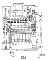
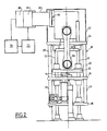
- Figures 1 and 2 are schematic views, partially broken away, from the front and side respectively of a device according to the invention.
- the device according to the invention comprises a chassis 10 slidably mounted on vertical columns 12 and comprising three superimposed horizontal plates 14, 16, 18 interconnected by columns 20, and a cover 22.
- the two lower plates 16 and 18 are crossed by the vertical piston rods 24 of a set of dosers (16 in number in the example shown) which are of a known type, for example described in French patent application 2,634,252 by the applicant.
- the metering units are at the lower ends of the piston rods 24 and have not been shown (except one of them, very schematically in phantom line, which comprises a cylinder 26, a piston 28 and an outlet nozzle 30) .
- each piston rod 24 comprises a fixed stop 34, such an annular ring, which is applied on the underside of the plate 32, and a cap 36 mounted for example by screwing at its upper end, to form the seat of a spring 38 which surrounds the piston rod 24 and the opposite end of which bears on the upper face of the plate 32.
- a sliding ring or sleeve is mounted in each orifice of the plate 32 through which a piston rod 24, to facilitate the sliding thereof.
- adjustable end stops 42 are in fact vertical threaded rods , which are screwed into holes in the plate 40 and which are immobilized in position by a lock nut 44.
- the plate 40 is itself carried by the upper plate 14 by means of four vertical threaded rods 46 which are screwed into threaded sleeves 48 of the transverse plate 40.
- Each threaded rod 46 is integral with a pinion 50 which is connected by a gear train with pinions 50 of the other threaded rods 46, so that the rotations of these threaded rods are synchronous, and with a drive mechanism comprising a vertical shaft 52 ending at its lower end by a flywheel 54.
- the rotation of the flywheel 54 makes it possible to drive the threaded rods 46 in rotation and therefore to modify the position of the plate 40 carrying the end-of-travel stops 42 relative to the plate 32 for driving the piston rods 24.
- the drive plate 32 is connected by a double connecting rod 56 - crank 58 system to the output shaft of a reduction gear 60 driven by the output shaft 62 of an electric motor 64, which is advantageously of the type without collector , to reduce maintenance and servicing issues.
- the electric motor 64 is also associated with a tachometric dynamo 66 making it possible to set a maximum speed of rotation of the shaft 62 of the motor electric, and to means 68, of the coding wheel type, making it possible to precisely determine the angular position of the output shaft of the motor 64.
- the output of the means 68 is in fact connected to the input of a counter 70, multiplying the number of pulses it receives from the means 68 and transmitting them to a control system 72, the output of which is connected to the tachometer dynamo 66 to directly control the speed of rotation of the motor 64.
- the variations in speed of this motor result in variations in speed and acceleration of the drive plate 32 and therefore of the piston rods 24.
- the maximum speed of rotation of the motor is fixed for example at a value of 2500 or 3000 revolutions per minute.
- the reduction gear has a transmission ratio of 1/32, i.e. each crank 58 performs one complete revolution (corresponding to a return stroke of a piston rod 24) for 32 revolutions of the shaft output 62 of the motor 64.
- the means 68 of the coding wheel type deliver for example 300 points per turn of the crank 58, which are transformed into 6000 points at the output of the coder 70.
- the control system 72 can therefore be very precise high.
- the maximum stroke of the piston rods is obtained when the top dead center and the bottom dead center of the piston rods are separated by an angle of 180 ° of rotation of the crankshaft 58.
- the piston strokes correspond to rotations of less than 180 ° of the crankshaft, the downward and upward movements of the piston rods are obtained by rotations in opposite directions of the crankshaft, and therefore of the electric motor.
- the plate 40 When the plate 40 is descended downward, the upper ends of the piston rods 24 are capable of coming to bear on the end stops 42 before reaching their previous top dead center.
- the plate 32 then continues its movement towards the high, by compressing the springs 38 of the piston rods 24, which by reason of their support on the stops 42, can no longer follow the movement of the plate 32.
- each stop 42 makes it possible to individually adjust the strokes of the piston rods 34.
Landscapes
- Engineering & Computer Science (AREA)
- Mechanical Engineering (AREA)
- Basic Packing Technique (AREA)
Applications Claiming Priority (2)
| Application Number | Priority Date | Filing Date | Title |
|---|---|---|---|
| FR9004889 | 1990-04-17 | ||
| FR9004889A FR2661015B1 (fr) | 1990-04-17 | 1990-04-17 | Dispositif de commande d'un ensemble de doseurs de produits liquides, visqueux ou pateux. |
Publications (1)
| Publication Number | Publication Date |
|---|---|
| EP0453349A1 true EP0453349A1 (de) | 1991-10-23 |
Family
ID=9395815
Family Applications (1)
| Application Number | Title | Priority Date | Filing Date |
|---|---|---|---|
| EP91400934A Withdrawn EP0453349A1 (de) | 1990-04-17 | 1991-04-05 | Steuervorrichtung für eine Gruppe von Dosiereinrichtungen für fliessfähige Medien, dickflüssige Produkte oder pastöse Massen |
Country Status (2)
| Country | Link |
|---|---|
| EP (1) | EP0453349A1 (de) |
| FR (1) | FR2661015B1 (de) |
Cited By (2)
| Publication number | Priority date | Publication date | Assignee | Title |
|---|---|---|---|---|
| FR2765856A1 (fr) * | 1997-07-14 | 1999-01-15 | Bosch Gmbh Robert | Dispositif de remplissage de recipients d'emballages par un produit fluide, pateux ou renfermant des particules |
| ES2125151A1 (es) * | 1995-10-03 | 1999-02-16 | Francisco Tejedor Garcia S A | Dispositivo dosificador para sustancias pastosas. |
Citations (3)
| Publication number | Priority date | Publication date | Assignee | Title |
|---|---|---|---|---|
| DE136125C (de) * | ||||
| US4256153A (en) * | 1979-07-09 | 1981-03-17 | Societe Francaise Pour Le Developpement De L'automatisme En Biologie | Device for simultaneous transfer of a plurality of liquids |
| FR2591284A1 (fr) * | 1985-12-10 | 1987-06-12 | Hassia Verpackung Ag | Pompe de remplissage pour doser des produits liquides ou pateux dans des recipients. |
-
1990
- 1990-04-17 FR FR9004889A patent/FR2661015B1/fr not_active Expired - Lifetime
-
1991
- 1991-04-05 EP EP91400934A patent/EP0453349A1/de not_active Withdrawn
Patent Citations (3)
| Publication number | Priority date | Publication date | Assignee | Title |
|---|---|---|---|---|
| DE136125C (de) * | ||||
| US4256153A (en) * | 1979-07-09 | 1981-03-17 | Societe Francaise Pour Le Developpement De L'automatisme En Biologie | Device for simultaneous transfer of a plurality of liquids |
| FR2591284A1 (fr) * | 1985-12-10 | 1987-06-12 | Hassia Verpackung Ag | Pompe de remplissage pour doser des produits liquides ou pateux dans des recipients. |
Cited By (2)
| Publication number | Priority date | Publication date | Assignee | Title |
|---|---|---|---|---|
| ES2125151A1 (es) * | 1995-10-03 | 1999-02-16 | Francisco Tejedor Garcia S A | Dispositivo dosificador para sustancias pastosas. |
| FR2765856A1 (fr) * | 1997-07-14 | 1999-01-15 | Bosch Gmbh Robert | Dispositif de remplissage de recipients d'emballages par un produit fluide, pateux ou renfermant des particules |
Also Published As
| Publication number | Publication date |
|---|---|
| FR2661015A1 (fr) | 1991-10-18 |
| FR2661015B1 (fr) | 1992-08-07 |
Similar Documents
| Publication | Publication Date | Title |
|---|---|---|
| US20240215634A1 (en) | Cone loading, weighing, filling, and twisting apparatus and method for mass production of smokable cannabis or hemp products | |
| EP0500831B1 (de) | Verfahren und vorrichtung zur einstellung von produktmengen, dosiert und verteilt mittels eines dosierspenders | |
| CA2207829A1 (fr) | Dispositif pour la formation de lots de produits et la separation desdits lots entre eux et reciproquement en vue de leur conditionnement | |
| GB2218021A (en) | Apparatus for bedding a pattern in a moulding flask | |
| EP0453349A1 (de) | Steuervorrichtung für eine Gruppe von Dosiereinrichtungen für fliessfähige Medien, dickflüssige Produkte oder pastöse Massen | |
| FR2647705A1 (fr) | Installation a table vibrante pour la fabrication de produits en beton | |
| BE897374A (fr) | Dispositif assurant le mouvement de pistons doseurs et tubes d'alimentation | |
| CN113830336B (zh) | 一种混合坚果包装机及工作方法 | |
| FR2628286A1 (fr) | Compteur de recolte pour moissonneuse-batteuse | |
| FR2903975A1 (fr) | Dispositif et procede de remplissage de reservoir en produit fluide. | |
| US2841938A (en) | Automatic cup dispensing and filling machine for fluids and semi-solids | |
| EP0688717A1 (de) | Verfahren und Vorrichtung zum Verpacken von Produkten wie grünen Bohnen | |
| US4850421A (en) | Shaking apparatus | |
| US2881716A (en) | Powered dough former | |
| EP1801017B1 (de) | Vorrichtung zum Befüllen von Behältern mit einer Einrichtung zum Regeln der Höhe | |
| US1451512A (en) | Measuring apparatus | |
| FR3018913A1 (fr) | Dispositif de pesage perfectionne destine a des appareils de dosage et de controle ponderal | |
| CN108146673A (zh) | 一种无级调速自动灌装机 | |
| CN220811809U (zh) | 一种新型搓盖机 | |
| FR2558149A1 (fr) | Distributeur de paraisons de verre a entrainement electrique | |
| EP0342116B1 (de) | Vorrichtung zum Ablegen eines Faserbandes in eine Kanne | |
| US1163465A (en) | Packeting apparatus. | |
| FR2521226A1 (fr) | Mecanisme de commande d'une pompe de dosage, en particulier pour une machine a nuancer des tons de peinture | |
| FR2515607A2 (fr) | Machine de remplissage de conteneurs | |
| FR2760426A1 (fr) | Procede de controle d'une machine de remplissage de conteneurs et machine de remplissage mettant en oeuvre le procede |
Legal Events
| Date | Code | Title | Description |
|---|---|---|---|
| PUAI | Public reference made under article 153(3) epc to a published international application that has entered the european phase |
Free format text: ORIGINAL CODE: 0009012 |
|
| AK | Designated contracting states |
Kind code of ref document: A1 Designated state(s): DE ES FR GB IT |
|
| 17P | Request for examination filed |
Effective date: 19920401 |
|
| 17Q | First examination report despatched |
Effective date: 19930212 |
|
| STAA | Information on the status of an ep patent application or granted ep patent |
Free format text: STATUS: THE APPLICATION IS DEEMED TO BE WITHDRAWN |
|
| 18D | Application deemed to be withdrawn |
Effective date: 19940208 |