EP0453087B1 - Optische Polarisations-Zustandsregelung - Google Patents
Optische Polarisations-Zustandsregelung Download PDFInfo
- Publication number
- EP0453087B1 EP0453087B1 EP91302193A EP91302193A EP0453087B1 EP 0453087 B1 EP0453087 B1 EP 0453087B1 EP 91302193 A EP91302193 A EP 91302193A EP 91302193 A EP91302193 A EP 91302193A EP 0453087 B1 EP0453087 B1 EP 0453087B1
- Authority
- EP
- European Patent Office
- Prior art keywords
- coil
- sop
- polarisation state
- optical fibre
- birefringence
- Prior art date
- Legal status (The legal status is an assumption and is not a legal conclusion. Google has not performed a legal analysis and makes no representation as to the accuracy of the status listed.)
- Expired - Lifetime
Links
- 230000003287 optical effect Effects 0.000 title description 6
- 239000000835 fiber Substances 0.000 claims description 16
- 239000013307 optical fiber Substances 0.000 claims description 11
- 238000006073 displacement reaction Methods 0.000 description 4
- 238000005452 bending Methods 0.000 description 2
- 238000010586 diagram Methods 0.000 description 2
- 230000000694 effects Effects 0.000 description 2
- NIXOWILDQLNWCW-UHFFFAOYSA-M Acrylate Chemical compound [O-]C(=O)C=C NIXOWILDQLNWCW-UHFFFAOYSA-M 0.000 description 1
- 230000001427 coherent effect Effects 0.000 description 1
- 125000004122 cyclic group Chemical group 0.000 description 1
- 230000001939 inductive effect Effects 0.000 description 1
- 230000000750 progressive effect Effects 0.000 description 1
- 230000007704 transition Effects 0.000 description 1
- 238000004804 winding Methods 0.000 description 1
Images


Classifications
-
- G—PHYSICS
- G02—OPTICS
- G02B—OPTICAL ELEMENTS, SYSTEMS OR APPARATUS
- G02B6/00—Light guides; Structural details of arrangements comprising light guides and other optical elements, e.g. couplings
- G02B6/24—Coupling light guides
- G02B6/26—Optical coupling means
- G02B6/27—Optical coupling means with polarisation selective and adjusting means
- G02B6/2726—Optical coupling means with polarisation selective and adjusting means in or on light guides, e.g. polarisation means assembled in a light guide
- G02B6/274—Optical coupling means with polarisation selective and adjusting means in or on light guides, e.g. polarisation means assembled in a light guide based on light guide birefringence, e.g. due to coupling between light guides
-
- G—PHYSICS
- G02—OPTICS
- G02B—OPTICAL ELEMENTS, SYSTEMS OR APPARATUS
- G02B6/00—Light guides; Structural details of arrangements comprising light guides and other optical elements, e.g. couplings
- G02B6/24—Coupling light guides
- G02B6/26—Optical coupling means
- G02B6/27—Optical coupling means with polarisation selective and adjusting means
- G02B6/2753—Optical coupling means with polarisation selective and adjusting means characterised by their function or use, i.e. of the complete device
- G02B6/2793—Controlling polarisation dependent loss, e.g. polarisation insensitivity, reducing the change in polarisation degree of the output light even if the input polarisation state fluctuates
-
- G—PHYSICS
- G02—OPTICS
- G02F—OPTICAL DEVICES OR ARRANGEMENTS FOR THE CONTROL OF LIGHT BY MODIFICATION OF THE OPTICAL PROPERTIES OF THE MEDIA OF THE ELEMENTS INVOLVED THEREIN; NON-LINEAR OPTICS; FREQUENCY-CHANGING OF LIGHT; OPTICAL LOGIC ELEMENTS; OPTICAL ANALOGUE/DIGITAL CONVERTERS
- G02F1/00—Devices or arrangements for the control of the intensity, colour, phase, polarisation or direction of light arriving from an independent light source, e.g. switching, gating or modulating; Non-linear optics
- G02F1/01—Devices or arrangements for the control of the intensity, colour, phase, polarisation or direction of light arriving from an independent light source, e.g. switching, gating or modulating; Non-linear optics for the control of the intensity, phase, polarisation or colour
- G02F1/0128—Devices or arrangements for the control of the intensity, colour, phase, polarisation or direction of light arriving from an independent light source, e.g. switching, gating or modulating; Non-linear optics for the control of the intensity, phase, polarisation or colour based on electro-mechanical, magneto-mechanical, elasto-optic effects
- G02F1/0131—Devices or arrangements for the control of the intensity, colour, phase, polarisation or direction of light arriving from an independent light source, e.g. switching, gating or modulating; Non-linear optics for the control of the intensity, phase, polarisation or colour based on electro-mechanical, magneto-mechanical, elasto-optic effects based on photo-elastic effects, e.g. mechanically induced birefringence
- G02F1/0134—Devices or arrangements for the control of the intensity, colour, phase, polarisation or direction of light arriving from an independent light source, e.g. switching, gating or modulating; Non-linear optics for the control of the intensity, phase, polarisation or colour based on electro-mechanical, magneto-mechanical, elasto-optic effects based on photo-elastic effects, e.g. mechanically induced birefringence in optical waveguides
-
- G—PHYSICS
- G02—OPTICS
- G02F—OPTICAL DEVICES OR ARRANGEMENTS FOR THE CONTROL OF LIGHT BY MODIFICATION OF THE OPTICAL PROPERTIES OF THE MEDIA OF THE ELEMENTS INVOLVED THEREIN; NON-LINEAR OPTICS; FREQUENCY-CHANGING OF LIGHT; OPTICAL LOGIC ELEMENTS; OPTICAL ANALOGUE/DIGITAL CONVERTERS
- G02F1/00—Devices or arrangements for the control of the intensity, colour, phase, polarisation or direction of light arriving from an independent light source, e.g. switching, gating or modulating; Non-linear optics
- G02F1/01—Devices or arrangements for the control of the intensity, colour, phase, polarisation or direction of light arriving from an independent light source, e.g. switching, gating or modulating; Non-linear optics for the control of the intensity, phase, polarisation or colour
- G02F1/0136—Devices or arrangements for the control of the intensity, colour, phase, polarisation or direction of light arriving from an independent light source, e.g. switching, gating or modulating; Non-linear optics for the control of the intensity, phase, polarisation or colour for the control of polarisation, e.g. state of polarisation [SOP] control, polarisation scrambling, TE-TM mode conversion or separation
Definitions
- This invention relates to optical polarisation state controllers, and in particular to such controllers in which the optical path lies in single mode optical fibre.
- the control of the state of polarisation (SOP) of an optical signal is an essential part of many optical sensor and coherent optics communications systems.
- the above-referenced paper is particularly directed to polarisation controllers in which adjustment of SOP is achieved by inducing a specific amount of linear birefringence into a length of single mode fibre by winding it into a planar coil with substantially co-linear ends, and then modifying the resulting birefringence by rotating the plane of the coil in such a way as to impart a controlled amount of twist into those ends.
- the paper described a tandem arrangement of two ⁇ /4 and a ⁇ /2 coil.
- the adjustment of the orientation of the two ⁇ /4 coils may be used to convert any given input SOP to a linear SOP, and then the adjustment of the orientation of the ⁇ /2 coil can be used to set the output to any chosen specific orientation of linear SOP.
- the mounting of the coils in a manner providing easy adjustment of the orientation of each imposes some difficulty, particularly when the adjustment is not performed manually, but is performed by transducers designed to enable the output SOP to be changed in any specifically desired time-varying manner.
- the present invention is specifically directed to SOP controllers with coils of single mode fibre in which control of the output SOP can be effected by linear distortions of those coils.
- an optical fibre polarisation state controller including a coil of single mode optical fibre mechanically coupled with a transducer, characterised in that the coil is a coil twisted out of planar form so as to make it circularly birefringent, and wherein the amount of the twist of the coil is adjustable under the control of the transducer.
- polarisation state controller embodying the invention in a preferred form. Also described is a tandem arrangement of two such controllers and an intervening quarter-wave coil all constructed using a single unbroken length of single mode fibre. Additionally there is described a tandem arrangement of three such controllers with an intervening quarter-wave coil between each pair of controllers, the controllers and coils similarly all being constructed using a single unbroken length of single mode fibre.
- FIG. 1 there is depicted a non-circular planar coil 10 of n turns of single mode fibre 11.
- This coil has two diametrically opposed straight portions 10′ linked by two diametrically opposed co-planar portions 10 ⁇ of uniform radius of curvature.
- this coil 10 is represented with its straight portions 10′, extending respectively from 'a' through 'b' to 'c' and from 'e' through 'f' to 'g', extending along the mid lines of the upper and lower faces of a cuboid with square end-faces m, n, s, t and u, w, x, y measuring 2r by 2r.
- the differential phase delay introduced into a length of single mode fibre by bending it to a particular radius of curvature is inversely proportional to the square of the radius of curvature, and directly proportional to the length of fibre over which the curvature is maintained. It follows therefore that, in the case of a circular planar coil, the differential phase delay is expected to be proportional to the inverse single power of the radius of curvature of the coil.
- the straight portions 10′ introduce no birefringence, and so the differential phase delay is provided exclusively by the curved portions 10 ⁇ with the result that the differential delay of the coil 10 is expected to be the same as that provided by a circular planar coil of radius 'r'. Accordingly theory predicts that the phase delay of the coil 10 is an inverse function of the distance separating the two straight portions 10′. It has been found in practice that when a length of single mode fibre 11 is wound without twisting into a planar form 10 of Figure 1 it exhibits a linear birefringence.
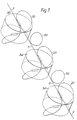
- planar form of 10 in Figure 1 is converted to a non-planar form depicted at 20 in Figure 2 by twisting the two planar uniform radius of curvature portions 13 of Figure 1 in opposite senses each through 45° to form the planar uniform radius of curvature portions 20 ⁇ that lie in orthogonal planes 21 and 22 respectively containing n, w, y, t and m, u, x, s.
- the planar uniform radius of curvature portions now extend respectively from 'w' through 'd' to 'y', and from 's' through 'k' to 'm'.
- the straight portions 10′ of Figure 1 are converted into planar lazy-S portions 20′ extending respectively from 'm' through 'b' to 'y', and from 'w' through 'f' to 's'.
- the lazy-S Over the length 'm' to 'b' the lazy-S has one curvature while over the region 'b' to 'y' it has the opposite curvature, and similarly the regions 'w' to 'f' and 'f' to 's' have oppositely directed curvatures.
- These oppositely directed curvatures of regions 20′ are much less strongly curved than the regions 20 ⁇ .
- the non-planar form of 20 of Figure 2 is found to exhibit circular birefringence instead of linear birefringence, and modulation of the distance separating the two regions 20′ by means of a loudspeaker coil and magnet assembly 34 (Figure 3, but not shown in Figure 2) is found, for a given displacement, to modulate that circular birefringence to a significantly greater extent than the corresponding modulation of linear birefringence produced by modulating the displacement of the planar coil of Figure 1.
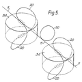
- a coil 20 comprising 50 turns (for illustrative convenience only one turn represented in Figure 5) of acrylate coated 125 um diameter single mode fibre with a 9 ⁇ m diameter optical core connected at 35 and 36 respectively to the centres of the front and back faces of the loudspeaker coil and magnet assembly 34 to provide an approximately 20 mm radius of curvature for the portions 20 ⁇ of the coil it was found that full-wave modulation (360° on the Poincaré sphere) of the circular birefringence was obtained by modulating the displacement between the front and back faces of the assembly by about 2mm.
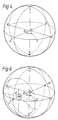
- All possible SOP's are represented in Figure 4 as points on the surface of a Poincaré sphere in which the poles L and R represent circularly polarised states, and the equator through HQV and P represent all possible linearly polarised states.
- the coil 20 exhibits circular birefringence, and so the eigenaxis for this coil passes through the points L and R on the Poincaré sphere of Figure 4.
- the output SOP can be set to any desired orientation of linearly polarised state but, for a linearly polarised input state, no elliptically polarised output state or circularly polarised output state is immediately accessible.
- Figure 5 comprising a tandem pair of coils 20, each with its own loudspeaker coil and magnet assembly 34, and an intervening coil 50 dimensioned and oriented to function as a quarter-wave ( ⁇ /4) linear birefringence retarder, provides the extra degree of freedom necessary to allow, for a given input SOP, the output of any chosen output SOP, linear or otherwise. This can be demonstrated with reference to the Poincaré spheres of Figures 4 and 6.
- linearly polarised light polarised in the plane corresponding to the point H in Figure 4 is launched into the first coil 20 of Figure 5.
- the output SOP from this first coil is therefore given by some point on the equatorial line through HQV and P of Figure 4.
- This light then passes through coil 50 which is a quarter-wave linear retarder. Since this retarder is a linear retarder, its eigenaxis lies in the equatorial plane, and since this retarder is a quarter-wave retarder, the rotation provided is through one right-angle. Choosing the eigenaxis for this linear retarder to extend through Q and P means that the plane of polarisation of the point H is at 45° to this eigenaxis. In other words, the light launched into the first coil 20 is plane polarised at 45° to the principal axes of the retarder formed by coil 50.
- the second coil 20 of Figure 5 like the first, exhibits circular birefringence, and so its eigenaxis passes through the points L′ and R′. If therefore the first coil 20 is capable of being modulated through a half-wave so as to be able to set the output SOP from the first coil 20 to any point on the arc from H through P to V, and if the second coil 20 is capable of being modulated through a full wave, then it is seen that any point on the Poincaré sphere can be reached. For instance a rotation through O given by the first coil 20 from the point H in Figure 4 to the point S is represented in Figure 6 as a rotation from L′ to the point S′.
- the tandem arrangement of Figure 5 involving the use of two coils 20 can be used to provide, for a given input SOP, any desired output SOP, and in this context it may be noted that this is achievable in a single length of single mode fibre without intermediate splices or couplers of any sort. However for a number of applications a facility is required for it to be possible to arrange the output SOP to track the SOP of some other device whose SOP can vary in an arbitrary manner. Using the tandem arrangement of Figure 5, a difficulty can be encountered.
- the output SOP is required to track cyclically around the great circle through L′ P R′ and Q of Figure 6 in the direction L′PR′Q.
- the energisation of the loudspeaker assembly 34 of the first coil 20 of Figure 5 is progressively changed to increase the birefringence angle ⁇ from 0° to 180° while the energisation of the loudspeaker assembly 34 of the second coil 20 is maintained at a constant value keeping the birefringence angle ⁇ at 0°.
- the output SOP tracks from L′ through P to R′.
- the energisation of the loudspeaker assembly 34 of the second coil 20 is changed to a new value, one that changes the birefringence angle ⁇ from 0° to 180°.
- This change produces no change in the output SOP because the input SOP to the second coil 20 is currently at the point R′, which is on the eigenaxis of this second coil 20.
- ⁇ can be progressively reduced from 180° to 0° to take the output SOP round the second half of the great circle, that is from R′ back to L′ by way of Q.
- L′ is reached, ⁇ can be reduced from 180° back to 0° without changing the output SOP, and the cycle can be repeated.
- the output SOP is required to track cyclically around the great circle through PV′Q and H′ in the direction PV′QH′.
- the energisation of the loudspeaker assembly 34 of the first coil 20 of Figure 5 is set to a value to maintain the birefringence angle O at 90°. This is maintained while the energisation of the loudspeaker assembly 34 of the second coil 20 is progressively changed to increase its birefringence angle ⁇ from 0° progressively up to 360° thereby taking the output SOP from P through V′Q and H′ and back to P again. If the cycle is to be repeated, the progressive change in energisation of the loudspeaker assembly 34 of the second coil 20 needs to be continued.
- the energisation of the loudspeaker assembly of the middle coil 20 is altered to change the birefringence angle ⁇ from O° to 360°, or from 360° to 0°, according to whether the transition across the half great circle L′PR′ is from the H′ hemisphere to the V′ hemisphere or from the V′ hemisphere to the H′ hemisphere.
- This change of birefringence angle ⁇ produces no effect upon the output SOP because the input SOP to the middle coil is currently at the point L′, which is the eigenaxis of this middle coil 20.
Landscapes
- Physics & Mathematics (AREA)
- General Physics & Mathematics (AREA)
- Optics & Photonics (AREA)
- Nonlinear Science (AREA)
- Audible-Bandwidth Dynamoelectric Transducers Other Than Pickups (AREA)
- Light Guides In General And Applications Therefor (AREA)
- Mechanical Light Control Or Optical Switches (AREA)
- Optical Fibers, Optical Fiber Cores, And Optical Fiber Bundles (AREA)
- Polarising Elements (AREA)
Claims (5)
- Lichtleitfaser-Polarisationszustands-Steuereinrichtung mit einer mechanisch mit einem Wandler (34) gekoppelten Spule (20) aus einer Monomode-Lichtleitfaser (11),
dadurch gekennzeichnet, daß die Spule eine Spule ist, die aus einer ebenen Form heraus verdrillt ist, so daß sie zirkular doppelbrechend gemacht ist, wobei das Ausmaß der Verdrillung der Spule unter der Steuerung des Wandlers einstellbar ist. - Lichtleitfaser-Polarisationszustands-Steuereinrichtung nach Anspruch 1, bei der die Spule zwei im wesentlichen diametral gegenüberliegende Bereiche (20′) mit einem relativ größeren Krümmungsradius aufweist, die über zwei im wesentlichen diametral gegenüberliegende im wesentliche ebene Bereiche (20˝) mit relativ kleinerem Krümmungsradius miteinander verbunden sind, wobei die Spule so geformt ist, daß die Ebenen der beiden ebenen Bereiche mit relativ kleinerem Krümmungsradius in im wesentlichen zueinander senkrechten Ebenen liegen, und wobei der Abstand der einen relativ größeren Krümmungsradius aufweisenden Bereiche unter der Steuerung des Wandlers einstellbar ist.
- Lichtleitfaser-Polarisationszustands-Steuereinrichtung nach Anspruch 1 oder 2, bei der der Wandler ein elektromechanischer Wandler ist.
- Tandemanordnung von zwei Lichtleitfaser-Polarisationszustands-Steuereinrichtungen nach Anspruch 1, 2 oder 3 und einer dazwischenliegenden aufgespulten Länge (50) einer Monomode-Lichtleitfaser, die eine lineare Viertelwellen-Doppelbrechung ergibt.
- Tandemanordnung von drei Lichtleitfaser-Polarisationszu- stands-Steuereinrichtungen nach Anspruch 1, 2 oder 3, wobei zwischen jedem Paar der drei Steuereinrichtungen eine dazwischenliegende aufgespulte Länge (50) der Monomode-Lichtleitfaser angeordnet ist, die eine lineare Viertelwellen-Doppelbrechung ergibt.
Applications Claiming Priority (2)
| Application Number | Priority Date | Filing Date | Title |
|---|---|---|---|
| GB9006867 | 1990-03-28 | ||
| GB9006867A GB2242538B (en) | 1990-03-28 | 1990-03-28 | Optical polarisation state controllers |
Publications (2)
| Publication Number | Publication Date |
|---|---|
| EP0453087A1 EP0453087A1 (de) | 1991-10-23 |
| EP0453087B1 true EP0453087B1 (de) | 1994-08-10 |
Family
ID=10673365
Family Applications (1)
| Application Number | Title | Priority Date | Filing Date |
|---|---|---|---|
| EP91302193A Expired - Lifetime EP0453087B1 (de) | 1990-03-28 | 1991-03-14 | Optische Polarisations-Zustandsregelung |
Country Status (6)
| Country | Link |
|---|---|
| US (1) | US5115480A (de) |
| EP (1) | EP0453087B1 (de) |
| JP (1) | JP3148272B2 (de) |
| AU (1) | AU632675B2 (de) |
| DE (1) | DE69103315T2 (de) |
| GB (1) | GB2242538B (de) |
Families Citing this family (8)
| Publication number | Priority date | Publication date | Assignee | Title |
|---|---|---|---|---|
| US5408545A (en) * | 1994-01-19 | 1995-04-18 | Dicon Fiberoptics | Depolarizer for fiber optic applications and method using same |
| US5598489A (en) * | 1994-07-27 | 1997-01-28 | Litton Systems, Inc. | Depolarized fiber optic rotation sensor with low faraday effect drift |
| US6608685B2 (en) | 2000-05-15 | 2003-08-19 | Ilx Lightwave Corporation | Tunable Fabry-Perot interferometer, and associated methods |
| GB0026413D0 (en) * | 2000-10-28 | 2000-12-13 | Bookham Technology Ltd | Polarisation dependent loss generators |
| US6721468B2 (en) | 2001-06-08 | 2004-04-13 | Ilx Lightwave Corporation | Resonantly driven fiber polarization scrambler |
| US6885782B2 (en) * | 2001-06-26 | 2005-04-26 | Ilx Lightwave Corporation | Feedback polarization controller |
| US10018785B2 (en) * | 2013-06-14 | 2018-07-10 | Exfo Inc. | Optical fiber modal distribution conditioner |
| US11016316B2 (en) | 2016-11-10 | 2021-05-25 | Intuitive Surgical Operations, Inc. | Polarization control with low polarization-mode dispersion |
Family Cites Families (8)
| Publication number | Priority date | Publication date | Assignee | Title |
|---|---|---|---|---|
| US4389090A (en) * | 1980-09-04 | 1983-06-21 | The Board Of Trustees Of Leland Stanford Jr. Univ. | Fiber optic polarization controller |
| US4495411A (en) * | 1982-10-27 | 1985-01-22 | The United States Of America As Represented By The Secretary Of The Navy | Fiber optic sensors operating at DC |
| US4697876A (en) * | 1983-02-25 | 1987-10-06 | Andrew Corporation | Fiber-optic rotation sensor |
| US4793678A (en) * | 1985-05-20 | 1988-12-27 | Nippon Telegraph And Telephone Corporation | Fiber optic polarization controller |
| GB2184253A (en) * | 1985-12-13 | 1987-06-17 | Stc Plc | Optical state-of-polarisation modulator |
| US4915468A (en) * | 1987-02-20 | 1990-04-10 | The Board Of Trustees Of The Leland Stanford Junior University | Apparatus using two-mode optical waveguide with non-circular core |
| US4799752A (en) * | 1987-09-21 | 1989-01-24 | Litton Systems, Inc. | Fiber optic gradient hydrophone and method of using same |
| US4960319A (en) * | 1989-10-04 | 1990-10-02 | Litton Systems, Inc. | Active polarization control servo and method |
-
1990
- 1990-03-28 GB GB9006867A patent/GB2242538B/en not_active Expired - Fee Related
-
1991
- 1991-03-14 EP EP91302193A patent/EP0453087B1/de not_active Expired - Lifetime
- 1991-03-14 DE DE69103315T patent/DE69103315T2/de not_active Expired - Fee Related
- 1991-03-19 US US07/671,453 patent/US5115480A/en not_active Expired - Lifetime
- 1991-03-20 AU AU73643/91A patent/AU632675B2/en not_active Ceased
- 1991-03-28 JP JP09002691A patent/JP3148272B2/ja not_active Expired - Fee Related
Also Published As
| Publication number | Publication date |
|---|---|
| GB9006867D0 (en) | 1990-05-23 |
| AU632675B2 (en) | 1993-01-07 |
| JPH0651148A (ja) | 1994-02-25 |
| JP3148272B2 (ja) | 2001-03-19 |
| EP0453087A1 (de) | 1991-10-23 |
| US5115480A (en) | 1992-05-19 |
| DE69103315D1 (de) | 1994-09-15 |
| GB2242538A (en) | 1991-10-02 |
| AU7364391A (en) | 1991-10-03 |
| DE69103315T2 (de) | 1994-12-01 |
| GB2242538B (en) | 1994-04-06 |
Similar Documents
| Publication | Publication Date | Title |
|---|---|---|
| US6445485B1 (en) | Micro-machine polarization-state controller | |
| US6233371B1 (en) | Optical fiber polarization controller | |
| EP0453087B1 (de) | Optische Polarisations-Zustandsregelung | |
| US4988170A (en) | Quasi-achromatic optical isolators and circulators | |
| US4341442A (en) | Fiber optical transmission filter with double-refraction element | |
| US4988169A (en) | Optical signal control method and apparatus | |
| CN1241043C (zh) | 偏振模式分散的仿真器和补偿器 | |
| EP2715422B1 (de) | Trennung mit variabler polarisation über strahlteilerrotation | |
| US4737005A (en) | Method for eliminating birefringence in a fiber optic coupler and a coupler polarization corrector | |
| JPH07218889A (ja) | 旋光装置 | |
| US5847872A (en) | Circumferentially isotropic phase plate, method of making the same, method of forming bundle of rays using the same, and polarization measuring apparatus and method using the same | |
| CN105891957A (zh) | 一种全光纤的一阶oam模式产生系统 | |
| EP0347994A2 (de) | Lamina zur Drehung der Polarisationsrichtung in einer optischen Fiber und ihre Anwendung | |
| JPH06147905A (ja) | 偏波変調器と光ファイバジャイロ | |
| GB2119536A (en) | Fibre optic Faraday rotation device and method | |
| KR100395658B1 (ko) | 광섬유 편광 조절장치 및 그를 이용한 편광도 감소 시스템 | |
| Luke et al. | Polarization maintaining single-mode fibre piezo-electric phase modulators | |
| RU1426274C (ru) | Адаптивное зеркало | |
| US20240402523A1 (en) | Fiber faraday rotator | |
| JPS6213008A (ja) | 均一磁界発生装置 | |
| SU1569783A1 (ru) | Сканирующее магнитоэлектрическое устройство | |
| JPS62127704A (ja) | 偏波制御回路 | |
| JPH08262394A (ja) | 多入力多出力光偏波コントローラ | |
| KR20260015617A (ko) | 광 스위칭 장치 | |
| Zak et al. | CURRENT-CONTROLLED PHASE RETARDATION PLATE |
Legal Events
| Date | Code | Title | Description |
|---|---|---|---|
| PUAI | Public reference made under article 153(3) epc to a published international application that has entered the european phase |
Free format text: ORIGINAL CODE: 0009012 |
|
| AK | Designated contracting states |
Kind code of ref document: A1 Designated state(s): DE DK ES FR GR IT |
|
| 17P | Request for examination filed |
Effective date: 19910926 |
|
| RAP1 | Party data changed (applicant data changed or rights of an application transferred) |
Owner name: NORTHERN TELECOM EUROPE LIMITED |
|
| 17Q | First examination report despatched |
Effective date: 19930625 |
|
| RAP1 | Party data changed (applicant data changed or rights of an application transferred) |
Owner name: NORTHERN TELECOM LIMITED |
|
| GRAA | (expected) grant |
Free format text: ORIGINAL CODE: 0009210 |
|
| AK | Designated contracting states |
Kind code of ref document: B1 Designated state(s): DE DK ES FR GR IT |
|
| PG25 | Lapsed in a contracting state [announced via postgrant information from national office to epo] |
Ref country code: IT Free format text: LAPSE BECAUSE OF FAILURE TO SUBMIT A TRANSLATION OF THE DESCRIPTION OR TO PAY THE FEE WITHIN THE PRE;WARNING: LAPSES OF ITALIAN PATENTS WITH EFFECTIVE DATE BEFORE 2007 MAY HAVE OCCURRED AT ANY TIME BEFORE 2007. THE CORRECT EFFECTIVE DATE MAY BE DIFFERENT FROM THE ONE RECORDED.SCRIBED TIME-LIMIT Effective date: 19940810 Ref country code: ES Free format text: THE PATENT HAS BEEN ANNULLED BY A DECISION OF A NATIONAL AUTHORITY Effective date: 19940810 Ref country code: GR Free format text: LAPSE BECAUSE OF FAILURE TO SUBMIT A TRANSLATION OF THE DESCRIPTION OR TO PAY THE FEE WITHIN THE PRESCRIBED TIME-LIMIT Effective date: 19940810 Ref country code: DK Effective date: 19940810 |
|
| ET | Fr: translation filed | ||
| REF | Corresponds to: |
Ref document number: 69103315 Country of ref document: DE Date of ref document: 19940915 |
|
| PLBE | No opposition filed within time limit |
Free format text: ORIGINAL CODE: 0009261 |
|
| STAA | Information on the status of an ep patent application or granted ep patent |
Free format text: STATUS: NO OPPOSITION FILED WITHIN TIME LIMIT |
|
| 26N | No opposition filed | ||
| REG | Reference to a national code |
Ref country code: FR Ref legal event code: CD |
|
| PGFP | Annual fee paid to national office [announced via postgrant information from national office to epo] |
Ref country code: DE Payment date: 20070330 Year of fee payment: 17 |
|
| PGFP | Annual fee paid to national office [announced via postgrant information from national office to epo] |
Ref country code: FR Payment date: 20070301 Year of fee payment: 17 |
|
| REG | Reference to a national code |
Ref country code: FR Ref legal event code: ST Effective date: 20081125 |
|
| PG25 | Lapsed in a contracting state [announced via postgrant information from national office to epo] |
Ref country code: DE Free format text: LAPSE BECAUSE OF NON-PAYMENT OF DUE FEES Effective date: 20081001 |
|
| PG25 | Lapsed in a contracting state [announced via postgrant information from national office to epo] |
Ref country code: FR Free format text: LAPSE BECAUSE OF NON-PAYMENT OF DUE FEES Effective date: 20080331 |