EP0453062A1 - Apparatus and method to reduce automotive engine emissions - Google Patents
Apparatus and method to reduce automotive engine emissions Download PDFInfo
- Publication number
- EP0453062A1 EP0453062A1 EP91300628A EP91300628A EP0453062A1 EP 0453062 A1 EP0453062 A1 EP 0453062A1 EP 91300628 A EP91300628 A EP 91300628A EP 91300628 A EP91300628 A EP 91300628A EP 0453062 A1 EP0453062 A1 EP 0453062A1
- Authority
- EP
- European Patent Office
- Prior art keywords
- catalyst
- sensor
- stream
- filter
- oxygen
- Prior art date
- Legal status (The legal status is an assumption and is not a legal conclusion. Google has not performed a legal analysis and makes no representation as to the accuracy of the status listed.)
- Granted
Links
Images


Classifications
-
- F—MECHANICAL ENGINEERING; LIGHTING; HEATING; WEAPONS; BLASTING
- F01—MACHINES OR ENGINES IN GENERAL; ENGINE PLANTS IN GENERAL; STEAM ENGINES
- F01N—GAS-FLOW SILENCERS OR EXHAUST APPARATUS FOR MACHINES OR ENGINES IN GENERAL; GAS-FLOW SILENCERS OR EXHAUST APPARATUS FOR INTERNAL COMBUSTION ENGINES
- F01N3/00—Exhaust or silencing apparatus having means for purifying, rendering innocuous, or otherwise treating exhaust
- F01N3/08—Exhaust or silencing apparatus having means for purifying, rendering innocuous, or otherwise treating exhaust for rendering innocuous
- F01N3/10—Exhaust or silencing apparatus having means for purifying, rendering innocuous, or otherwise treating exhaust for rendering innocuous by thermal or catalytic conversion of noxious components of exhaust
- F01N3/24—Exhaust or silencing apparatus having means for purifying, rendering innocuous, or otherwise treating exhaust for rendering innocuous by thermal or catalytic conversion of noxious components of exhaust characterised by constructional aspects of converting apparatus
- F01N3/28—Construction of catalytic reactors
-
- F—MECHANICAL ENGINEERING; LIGHTING; HEATING; WEAPONS; BLASTING
- F02—COMBUSTION ENGINES; HOT-GAS OR COMBUSTION-PRODUCT ENGINE PLANTS
- F02D—CONTROLLING COMBUSTION ENGINES
- F02D41/00—Electrical control of supply of combustible mixture or its constituents
- F02D41/02—Circuit arrangements for generating control signals
- F02D41/14—Introducing closed-loop corrections
- F02D41/1438—Introducing closed-loop corrections using means for determining characteristics of the combustion gases; Sensors therefor
- F02D41/1439—Introducing closed-loop corrections using means for determining characteristics of the combustion gases; Sensors therefor characterised by the position of the sensor
- F02D41/1441—Plural sensors
-
- F—MECHANICAL ENGINEERING; LIGHTING; HEATING; WEAPONS; BLASTING
- F02—COMBUSTION ENGINES; HOT-GAS OR COMBUSTION-PRODUCT ENGINE PLANTS
- F02D—CONTROLLING COMBUSTION ENGINES
- F02D41/00—Electrical control of supply of combustible mixture or its constituents
- F02D41/02—Circuit arrangements for generating control signals
- F02D41/14—Introducing closed-loop corrections
- F02D41/1438—Introducing closed-loop corrections using means for determining characteristics of the combustion gases; Sensors therefor
- F02D41/1444—Introducing closed-loop corrections using means for determining characteristics of the combustion gases; Sensors therefor characterised by the characteristics of the combustion gases
- F02D41/1454—Introducing closed-loop corrections using means for determining characteristics of the combustion gases; Sensors therefor characterised by the characteristics of the combustion gases the characteristics being an oxygen content or concentration or the air-fuel ratio
- F02D41/1456—Introducing closed-loop corrections using means for determining characteristics of the combustion gases; Sensors therefor characterised by the characteristics of the combustion gases the characteristics being an oxygen content or concentration or the air-fuel ratio with sensor output signal being linear or quasi-linear with the concentration of oxygen
-
- Y—GENERAL TAGGING OF NEW TECHNOLOGICAL DEVELOPMENTS; GENERAL TAGGING OF CROSS-SECTIONAL TECHNOLOGIES SPANNING OVER SEVERAL SECTIONS OF THE IPC; TECHNICAL SUBJECTS COVERED BY FORMER USPC CROSS-REFERENCE ART COLLECTIONS [XRACs] AND DIGESTS
- Y02—TECHNOLOGIES OR APPLICATIONS FOR MITIGATION OR ADAPTATION AGAINST CLIMATE CHANGE
- Y02T—CLIMATE CHANGE MITIGATION TECHNOLOGIES RELATED TO TRANSPORTATION
- Y02T10/00—Road transport of goods or passengers
- Y02T10/10—Internal combustion engine [ICE] based vehicles
- Y02T10/12—Improving ICE efficiencies
Definitions
- This invention relates to apparatus and methods for purifying automotive engine emissions, and more particularly to such apparatus and methods which concurrently use catalysis and air/fuel ratio feedback to maximise purification.
- the prior art has followed essentially two paths: (i) change the chemical or physical arrangement of catalyst elements within the conversion chamber, or (ii) modify the gaseous emissions delivered to the catalyst conversion chamber.
- the prior art has commercially evolved a three-way catalyst (that which converts HC, CO and NO x ) by use of a combination of precious metals coated onto a stabilised alumina substrate which in turn is carried on a monolithic ceramic cellular core.
- the core is engineered to pass emissions therethrough along a straight, uninterrupted axial flow at various space velocities.
- Such catalyst construction cannot, by itself, overcome conversion deficiencies due to random and statistically unpredictable oxygen level deviations (chemical noise) as well as statistically predictable deviations of the oxygen levels (transient excursions) which may occur, particularly during warm-up and cold-start of the engine.
- Chemical noise in the exhaust gas is due to mixing of turbulent rich and lean eddy currents that result respectively from variable cylinder exhaust gases and incomplete cylinder burns.
- Combustion explosions inherently vary from cylinder to cylinder due to different burn rates and different pulsing waves. The variation is compounded by the different lengths of exhaust ports leading to the mixing of the exhaust gases into a common stream.
- Chemical noise deviations cannot be predicted and do inhibit ideal oxygen level control.
- Transient excursions denote a temporary real change from an average oxygen level due to inadequate combustion control and should be accurately sensed for compensation. Transient excursions are not considered random and are predictable.
- This invention has found dramatic improvement by uniquely combining a low mass, highly loaded filter catalyst upstream of a linear, wide-range, universal exhaust gas oxygen (UEGO) sensor in a feedback control loop with an A/F ratio modifier; such combination treats the exhaust gas before it enters a main conversion catalyst.
- UEGO linear, wide-range, universal exhaust gas oxygen
- Applicant is unaware of any prior art that (a) contemplates use of filter catalysts (those capable of filtering out random combustion effects or chemical noise) while converting usually only a minor amount of the noxious emissions from a moving vehicle; (b) uses a single UEGO sensor upstream of the main catalyst and downstream of the filtering catalyst; and (c) deploys automatic compensation for degradation of either the catalyst or sensor with time.
- Switching sensors have a very steep change in signal at or about stoichiometry.
- a single switch-type exhaust gas sensor in an upstream position relative to the catalyst body was used in U.S. patent 4,000,614 (1977).
- the sensor was placed in a feedback control loop and was only able to achieve A/F ratio control accuracies within ⁇ 1-2% of stoichiometry.
- This poor range of tolerance for A/F ratio is characteristic of excessive hunting and overcorrecting by the oxygen sensor due in part to its placement and in part to the employment of a switchpoint type sensor, characteristic of the sensors used during the 1970's.
- the US-A-4,761,950 employs software (see jumpback control algorithm in Figure 4D) which uses downstream sensor information to modify an upstream sensor placed about a single catalytic body and then compares the information for control purposes.
- the sensors are of the switchpoint-type and the system suffers from A/F ratio control accuracy problems and comparator delay.
- a system for cleansing the gaseous emission stream generated by the combustion of an A/F mixture within cylinders of an internal combustion engine comprising, a low mass, three-way filter catalyst stationed close to the source of said stream effective to filter out random combustion effects within said stream, a high mass, three-way main catalyst stationed downstream of said filter catalyst effective to convert the remainder of noxious emissions in said stream to desired levels, a continuous universal exhaust gas oxygen sensor stationed in said stream between said catalysts effective to rapidly and accurately indicate the level of oxygen within the stream leaving the filter catalyst, and proportional control means for adjusting in closed loop the A/F ratio of said mixture in interactive response to a deviation of the sensed oxygen level from a target level.
- the system embodying the invention controls unwanted emissions to unprecedented lower levels by improving a closed loop A/F ratio feedback system between an engine and catalyst.
- the system provides superior feedback response at frequencies of 3-6Hz for the loop and a sensor that responds within a time period of less than 60 milliseconds, and provides a resolution control for maintaining A/F ratio within ⁇ .01-.02% of stoichiometry irrespective of random combustion effects, variations in fuel injection, variations in intake air, variations in cylinder-to-cylinder conditions, and variations in exhaust turbulence.
- the UEGO sensor is interactively related to the filter catalyst in time response to eliminate chemical noise and change A/F ratio feedback loop gain to compensate for ageing. This interaction is provided by placing the UEGO sensor downstream of the filter catalyst, limiting the conversion efficiency of the filter catalyst, and arranging the interactive relationship between the sensor and an A/F ratio controller, affecting the injection of fuel and thus the filter catalyst, to be highly improved in response capability. Such interaction ensures that the sensor operates complementary and opposite to the sensitivity of the filter catalyst to achieve chemical noise elimination.
- low mass means less than 500 grams and low volume means less than 20 in3; high mass means greater than 1000 grams and high volume means greater than 40 in3; filter catalyst means a catalyst having predetermined limited conversion efficiency, i.e., 40-60% efficiency under non-idle conditions of the engine with only up to 80-85% efficiency at idle conditions at an idle space velocity of 20K/hr.
- the filter catalyst is heavily loaded (i.e., 40-60 gm/ft3 of precious metal) and is 2-4 inches in length and about 16-20 in3 in volume.
- the filter catalyst is located within a distance of 1-4 inches of the source of a unitary exhaust stream and will provide 10-20% of the total catalyst capacity.
- downstream stationing means downward along the direction of flow wide-range means universal for accurately measuring A/F ratio at rich, lean, or about stoichiometry conditions.
- the senor is constructed to have two or more cells (i.e., pumping and reference cells) to achieve continuous linear output characteristics and symmetrical (above or below stoichiometry) time response.
- Such sensor preferably has a spinel layer removed from the electrodes while utilizing a thin wall diffusion path provided by a porous layer over the diffusion cavity.
- the sensor has sensing elements with a low mass of less than five grams and preferably uses four enclosed electrodes with the sensor having a frequency response of less than 60 milliseconds.
- Such linearized sensor will have a performance characterised by ⁇ 3% accuracy (of operating point) at lambdas of .7 and 1.4, with increasing accuracy toward lambda of 1 where it will be no more than ⁇ .07%; lambda means the ratio of actual A/F to stoichiometric A/F.
- the main catalyst is stationed preferably about four inches from the upstream filter catalyst and is loaded to convert up to 90% of the emissions at a space velocity of 400K/hr at a heavy engine load.
- the method mode of this invention for compensating chemical ageing of a catalyst system comprised of two in-line catalysts and a linearized UEGO sensor interposed between such catalysts, the upstream catalyst being loaded to effect limited conversion of the noxious emissions and to filter out random combustion effects of the emissions and changes in voltage of the sensor being used to control the A/F mixture at or in a desired range, comprises the steps of: (a) empirically establishing the chemical degradation rate of the upstream catalyst with a predetermined type of usage that progressively reduces conversion efficiency and permits greater gaseous noxious emissions to pass therethrough; (b) empirically establishing the degradation rate of the sensor with normal usage that progressively provides slower response and reduces the gain of the sensor; (c) establishing an initial gain characteristic for the feedback control loop based on the empirically established rate of degradation so that as the sensor ages, its loss in gain characteristic will offset the increase in passage of noxious gaseous effects through the upstream catalyst as a result of degradation thereby maintaining a uniform loop response and a level conversion of the gaseous
- the gain of said feedback control loop is set at 20% below that needed for normal sensing.
- the design of the sensor should provide for a higher frequency response capability than needed for maximum efficiency of an aged catalyst.
- An interactive catalyst-fuel injector feedback system embodying the invention achieves unprecedented tight control of mean A/F ratio within a resolution of ⁇ .01-.02% of stoichiometry in real time, such as within a response time of less than 60 milliseconds and the system compensates for degradation of the catalyst body or fuel system control over time that effects such accurate resolution and quickness of response in spite of variables of engine characteristics and degradation of the catalyst bodies or fuel system over time that effect such accurate resolution and quickness of response.
- This is achieved herein by a unique interactive combination of a small mass-volume filter catalyst and a linear, wide-range, multiple-cell, low mass exhaust gas oxygen sensor that is isolated from contamination and ambient temperature, the combination being positioned upstream of a conventional three-way catalyst body.
- the elements of a system for cleansing the gaseous emissions generated by the combustion within an internal combustion engine includes: an engine 10 having a combustion chamber 11 and an A/F supply 12 comprising an air intake 15, an air throttle 17, an A/F meter 16, and a single point fuel injector 13; an ultrasonic fuel atomiser 14 may be used in some instances.
- Exhaust channels 18, from each of the combustion cylinders or chambers 11, lead and merge into a common exhaust stream 19.
- a low mass-volume filter catalyst 20 located close to the point at which the exhaust channels merge into a common stream.
- a wide-range universal exhaust gas oxygen (UEGO) sensor 21 is located immediately downstream of the filter catalyst, and a main catalyst 22 is located downstream of the sensor 21.
- Interactive controls 23 in part are integral with the exhaust gas sensor construction and in part link sensor 21 with the fuel injector 13 and other engine parameters in a closed loop feedback system.
- the filter catalyst 20 must be stationed in the emission stream with care and be structured to have a low mass-volume, three-way capability to filter out random combustion effects within the stream. Random combustion effects appear as turbulent rich and lean eddy currents contributed by the varying conditions of each individual combustion cylinder; the eddy currents represent a mixture of regular completed cylinder exhaust and incomplete cylinder combustion effects. The eddy currents are random.
- the catalyst 20 should have a low mass of about 300-500 grams and a low volume of about 15-20 in3, which together will desirably filter frequencies higher than 10Hz.
- the filter catalyst should have a length which is relatively short, about 2-4 inches, if the cross-sectional configuration is circular.
- the filter catalyst should be designed to have a high space velocity (i.e., at least 50K/hr at engine idle and at least 350K/hr at wide-open throttle).
- the filter catalyst will represent only 10-20% of the total catalyst volume for the entire system (filter and main catalysts).
- Such catalyst may be supported on a monolithic structure having a cellular density of 200-400 cells per square inch, or may be a wire mesh support.
- the ceramic cellular monolith type of support may operate in close coupled relationship to the exhaust manifold; a conventional washcoating may be used to stabilise the monolith for high temperature usage at such location.
- the filter catalyst should desirably be placed as close as possible to the source of the exhaust stream without damaging the effectiveness of the filter catalyst. In the preferred embodiment, such stationing is within 3-4 inches of the source of the emission stream 19 (location where cylinder exhausts merge as a unitary stream).
- the filter catalyst must have a heavy precious metal loading, particularly in the range of 40-60 gm/ft3 of precious metal.
- the precious metal may be comprised of platinum, palladium or rhodium, in combination or separately, to provide both oxidation and reduction of noxious elements within the emission stream, as is well known. It is important that such filter catalyst be capable of converting only a minor proportion (i.e., 40-60%) of noxious emission elements under heavy engine loading and up to 80-85% under idle conditions); this is brought about by controlling the mass, precious metal loading, size, and space velocity of the filter catalyst.
- Such filter catalyst will be capable of eliminating chemical noise because such noise has a high frequency well within the filtering capacity of such a small mass-volume aged or non-aged catalyst.
- the lowest anticipated chemical noise frequency emitted by the combustion cylinder is about 10Hz; this is well within the 4Hz filtering capacity of such catalyst.
- the conversion capability of such a new filter catalyst goes somewhat beyond removing random combustion effects for chemical noise because the filter catalyst design must allow for the inevitable ageing degradation of the catalyst.
- Limit cycle frequency is the inverse of time taken to complete a rich to lean and back to rich control cycle. Limit cycle frequency is determined by the collective delays in the control loop and includes sensor response, gas transport delay, emission control electronics delays, and software algorithm delays.
- the essential characteristics required of a sensor to cooperate in the combination invention herein includes at least the basic Nernst-type electrochemical cell, often referred to as a switching exhaust gas oxygen sensor. Although this basic building block of the sensor is necessary, it is important that the final sensor not be of the switching type or step function, but include the refinements set forth herein.
- switchpoint oxygen sensors are: (a) their inability to accurately determine A/F ratio at accuracies greater than 1% and undesirable sensor response time as well as switching time; and (b) cannot measure transient deviations of A/F ratio close to stoichiometry resulting from such things as throttle movements or transmission shifts, without an increase in tailpipe emissions.
- Sensor response time is the time required for a sensor to establish equilibrium exhaust gas conditions at the electrode/electrolyte interface after a gas transition zone passes the sensor.
- Switching time is that time that a sensor takes to switch its voltage after establishment of gas equilibrium conditions at the interface. The two response times are frequently added together and described as the sensor response time.
- the response behaviour of the switchpoint sensor is complex and causes off-target adjustments.
- the Nernst-type electrochemical cell includes (as shown in Figure 2) a solid electrolyte 30 typically comprised of partially stabilised zirconia, which conducts oxygen ions between electrodes 31, 32 (usually platinum) on its opposite sides with electrode 31 exposed to air and the other electrode 32 exposed to exhaust gas.
- the electrodes are coated with protective spinel layers and these layers contribute to the sensor response slowness and complexity.
- An electromotive force (emf) is developed due to the difference in oxygen partial pressure in each of the air and exhaust gas.
- the voltage output V changes sharply at stoichiometric levels (an A/F ratio of 14.7), as shown in Figure 3.
- Such switchpoint type of exhaust gas sensor can only indicate when stoichiometry has been achieved, but it cannot tell you how lean or rich the A/F ratio is at any one point. Thus, even if such type of sensor were to be linearized, its basic function prevents it from achieving needed improvements in system control.
- the sensor required for this invention includes the additional elements of: (a) dual cells 40, 41 (41 being the conventional Nernst-type sensing cell, and 40 being a pumping cell exhibiting a pumping current proportional to the A/F ratio); (b) a diffusion layer 43 (preferably supported on a plug) imposed between the two cells forms an aperture to control the quantity of oxygen molecules which arrive at the cavity between the cells while leaving the electrodes 42 with no cating or covering [the aperture of this diffusion layer may be closed by a special porous diffusion layer to again control the steady arrival of oxygen molecules devoid of contamination effects]; (c) a reversing circuit 44 to pump oxygen into a restricted volume between the two cells both during rich exhaust gas conditions and oxygen out of such restricted volume during lean exhaust gas conditions.
- This reversing circuit tends to maintain a stoichiometric mixture within the restricted volume between the cells. Thus, variation in time delays are avoided. Variability due to temperature conditions of the air or exhaust gas is eliminated by deploying embedded heater elements 45, 46 in ceramic elements separated but placed exterior to the two cells 40, 41, as shown in Figure 4. Temperature effects are minimised by the dual cell arrangement.
- the platinum electrodes are preferably uncovered to improve sensor response behaviour with no spinel layers.
- the output voltage of such a universal or wide-range exhaust gas sensor will be as that shown in Figure 5.
- Such a sensor construction is multiple-celled, wide-ranged, linearized, and has a response time of less than 60 milliseconds (response time is 63% of the total response of A/F change).
- This construction provides improved sensing and control of engine A/F ratio and thus emissions by providing the following specific capabilities which cannot be attained with present switchpoint sensors: (a) measurement of all A/F ratios that are encountered in engine operation; (b) high accuracy measurement of A/F ratio away from stoichiometry; (c) a faster response to sense A/F ratio changes; (d) a more stable and symmetrical response behaviour to rich to lean and lean to rich A/F ratio changes; (e) less sensitivity to exhaust temperature changes; and (f) more flexibility to design variations in desired response time characteristics.
- the sensing element cells have a low mass of less than five grams and the sensor provides ⁇ 3% accuracy (of operating point) at lambdas of .7 and 1.4 with increasing accuracy toward lambda of 1 where it will be no more than ⁇ .07%.
- the filter catalyst, sensor, and fuel injector must be interrelated to achieve a fast response time by selecting the closed loop gain (multiplying factor used on the sensor signal to apply adjustment power to the A/F ratio controller or fuel injector) and limit cycle frequency.
- the limit cycle frequency of the feedback control loop should be 3Hz or greater and the gain set 20% below normal to permit compensation for variability in the equipment and ageing of precious metal.
- Variability is used herein to mean variations within the fuel injector from engine to engine, variations in the sensor from system to system, and variations in air intake within the engine from cylinder to cylinder, and variation of burn rate within a single engine cylinder.
- Ageing is used herein to mean the poisoning or sintering of precious metals on the catalyst with the expiration of time.
- the gain and phase shift is shaped (i.e., by manipulating the capacitance and diffusion coefficient of the UEGO sensor) to make the sensor work with filter catalyst.
- the simplest interaction is to connect the sensor to the fuel injector in a direct proportional closed loop feedback while ensuring that the filter catalyst is sized and matched to the response of the sensor to provide only filtering (eliminate chemical noise) and convert a minor proportion of the noxious elements within the exhaust gas.
- Proportional means a continuous linear relation between output and input.
- the primary feedback loop provide a proportional-integral (PI) control method, similar to a part of the controller described in the SAE technical publication by J. Ishii, M. Amano, T. Yamauchi, N. Kurihara, entitled “Wide-Range Air-Fuel Ratio Control System", Feb. 29, 1988 (SAE publication 880134) on in U.S. patent 3,939,654.
- PI proportional-integral
- an adaptive feedback loop may be further incorporated in addition to the primary feedback loop to provide corrections to the injector and open loop sensor coefficients for various airflow/speed combinations.
- the injector power is modified by open loop (feed forward) information obtained from temperature, speed of the engine, and engine load.
- the gain setting for the feedback loop must be arranged so that it is about 15-25% below that predetermined to normally amplify the expected signals received from the filter catalyst, taking into account the designed mass and size of such filter catalyst.
- the filter catalyst is fresh, the millisecond amplitude variations in the A/F mixture entering the filter catalyst will be subdued upon exiting from such catalyst resulting from the elimination of chemical noise. The amplitude of such variations prior to passing the exhaust gas sensor will be subdued to normal and transient excursions.
- the sensor will then, with its quick response (.060 of a second phase shift), transmit a highly accurate voltage corresponding to the sensed amplitude, and the microprocessor will convert the voltage signal to an opposite value which changes the injector power function causing the A/F mixture being delivered to the filter catalyst to have reduced variation.
- the main three-way catalyst will then be more effective in converting the remainder of the noxious elements when the A/F ratio is relatively close to stoichiometry resulting in the final variation which almost assumes a straight line.
- the filter catalyst When the filter catalyst is substantially aged, such as will occur at vehicle miles above 50,000, the amplitude of the A/F ratio will have exaggerated swings due to the inability of the filter catalyst to dampen such amplitudes and eliminate some of the chemical noise to the same degree as when fresh.
- the larger A/F ratio swings that occur past an aged filter catalyst act to increase feedback loop gain, thus increasing sensitivity.
- the sensor will have, during the same time period, experienced some degradation which means that it will detect a lesser amount of the A/F ratio change. The degradation of the sensor acts to decrease the feedback loop gain to a lesser extent. Overall, the combined catalyst-sensor interaction will increase feedback loop gain with ageing thereby causing more rapid correction of A/F ratio deviations.
- An aged catalyst requires higher frequency and lower magnitude A/F ratio excursions to maintain high conversion efficiency.
Landscapes
- Engineering & Computer Science (AREA)
- Chemical & Material Sciences (AREA)
- Chemical Kinetics & Catalysis (AREA)
- Combustion & Propulsion (AREA)
- Mechanical Engineering (AREA)
- General Engineering & Computer Science (AREA)
- Health & Medical Sciences (AREA)
- Toxicology (AREA)
- Electrical Control Of Air Or Fuel Supplied To Internal-Combustion Engine (AREA)
- Exhaust Gas After Treatment (AREA)
- Combined Controls Of Internal Combustion Engines (AREA)
Abstract
Description
- This invention relates to apparatus and methods for purifying automotive engine emissions, and more particularly to such apparatus and methods which concurrently use catalysis and air/fuel ratio feedback to maximise purification.
- To improve the conversion efficiency of a catalyst system, the prior art has followed essentially two paths: (i) change the chemical or physical arrangement of catalyst elements within the conversion chamber, or (ii) modify the gaseous emissions delivered to the catalyst conversion chamber. With respect to changing the catalyst elements, the prior art has commercially evolved a three-way catalyst (that which converts HC, CO and NOx) by use of a combination of precious metals coated onto a stabilised alumina substrate which in turn is carried on a monolithic ceramic cellular core. The core is engineered to pass emissions therethrough along a straight, uninterrupted axial flow at various space velocities. Such catalyst construction cannot, by itself, overcome conversion deficiencies due to random and statistically unpredictable oxygen level deviations (chemical noise) as well as statistically predictable deviations of the oxygen levels (transient excursions) which may occur, particularly during warm-up and cold-start of the engine. Chemical noise in the exhaust gas is due to mixing of turbulent rich and lean eddy currents that result respectively from variable cylinder exhaust gases and incomplete cylinder burns. Combustion explosions inherently vary from cylinder to cylinder due to different burn rates and different pulsing waves. The variation is compounded by the different lengths of exhaust ports leading to the mixing of the exhaust gases into a common stream. Chemical noise deviations cannot be predicted and do inhibit ideal oxygen level control. Transient excursions denote a temporary real change from an average oxygen level due to inadequate combustion control and should be accurately sensed for compensation. Transient excursions are not considered random and are predictable.
- With respect to modifying the delivered emission gas, the prior art has found that the closer the combustion air/fuel (A/F) ratio in the engine is to stoichiometry, the lower will be the volume of noxious elements (HC, CO, NOx) delivered to the catalyst chamber for conversion. Although A/F ratio feedback systems have been deployed, transient and random combustion effects still prevail preventing the catalysts from achieving advanced levels of conversion efficiencies so necessary to anticipated mandated federal levels. Even small A/F measurement inaccuracies or small time delays in sensor detection and feedback result in hunting of the A/F adjustment and inability to achieve anticipated mandated federal levels for 1994 (gm/mi at between 75,000-100,000 miles of vehicle use) of .25-31 HC, 3.4-4.2 CO, .4 NOx, and .29-.36 total hydrocarbons (THC). Moreover, such random effects are progressively exaggerated by ageing of the catalyst and feedback system with time preventing the system from achieving anticipated federal long-life requirements beginning in years 2002 and beyond (at 100,000 miles) which may be essentially reduced to half of the anticipated 1994 requirements.
- This invention has found dramatic improvement by uniquely combining a low mass, highly loaded filter catalyst upstream of a linear, wide-range, universal exhaust gas oxygen (UEGO) sensor in a feedback control loop with an A/F ratio modifier; such combination treats the exhaust gas before it enters a main conversion catalyst. Applicant is unaware of any prior art that (a) contemplates use of filter catalysts (those capable of filtering out random combustion effects or chemical noise) while converting usually only a minor amount of the noxious emissions from a moving vehicle; (b) uses a single UEGO sensor upstream of the main catalyst and downstream of the filtering catalyst; and (c) deploys automatic compensation for degradation of either the catalyst or sensor with time.
- The first design of a basic nonswitching exhaust gas sensor, necessary to this invention, first appeared about 1981 with the issuance of the Hetrick U.S. patent 4,272,329 (assigned to Ford Motor Company). This patent describes a multiple-cell oxygen sensor that is more useful for meeting tighter emission standards. The sensor of this patent provides a linearized output that measures more accurately a wider range of A/F ratio while being substantially temperature insensitive to avoid thermally induced inaccuracies. Papers published during 1986 and 1988 show the acceptance in the technical community of such UEGO sensor when applied to an extended range of A/F ratios using a closed loop feedback system (closed loop being used herein to mean a controlled quantity as measured and compared to a standard representing desired performance). Such articles include: (1) I. Murase, A. Moriyama, and M. Nakai, "A Portable Fast Response Air-Fuel Ratio Meter Using An Extended Range Oxygen Sensor", SAE Paper 880559, Feb. 29, 1988; (2) J. Ishii, M. Amano, T. Yamauchi, and N. Kurihara, "Wide-Range Air-Fuel Ratio Control System", SAE Paper 880134, Feb. 29, 1988; (3) S. Ueno, N. Ichikawa, S. Suzuki and K. Terakado, "Wide-Range Air-Fuel Ratio Sensor, SAE Paper 860409, 1986; and (4) S. Suzuki, T. Sasayama, M. Miki, M. Ohsuga and S. Tanaka, "Air-Fuel Ratio Sensor For Rich, Stoichiometric and Lean Ranges", SAE Paper 860408, 1986.
- What the design evolution of such UEGO sensor lacks is how to use it in a system to realize its accuracy potential. Applications of more primitive exhaust gas sensors (switching sensors) in the prior art have used (a) a single switching sensor with one or two catalyst bodies, or (b) dual switching sensors with one or two catalyst bodies. Switching sensors have a very steep change in signal at or about stoichiometry.
- A single switch-type exhaust gas sensor in an upstream position relative to the catalyst body was used in U.S. patent 4,000,614 (1977). The sensor was placed in a feedback control loop and was only able to achieve A/F ratio control accuracies within ± 1-2% of stoichiometry. This poor range of tolerance for A/F ratio is characteristic of excessive hunting and overcorrecting by the oxygen sensor due in part to its placement and in part to the employment of a switchpoint type sensor, characteristic of the sensors used during the 1970's.
- An attempt was made in U.S. patent 3,961,477 (1976) to place the exhaust gas sensor between two catalyst bodies, the upstream body being an oxidation catalyst and the downstream body being a reducing catalyst. This patent is also an early example of closed loop A/F ratio control for catalysis and is representative of one of the most effective concepts of the 1970's. The A/F ratio tolerance capability is poor due in part to the use of a switchpoint-type exhaust gas sensor and the use of air injection immediately upstream of the sensor which detracts from its ability to accurately sense the oxygen content of the emissions. This reference does not describe the catalyst with respect to loading or effectiveness.
- Use of more than one exhaust gas sensor is included in U.S. patents 3,939,654; 4,251,990; and 4,761,950. In the US-A-3,939,654, step function (switch-type) oxygen sensors were placed upstream and downstream of a catalyst body while using a closed loop feedback system to a fuel injector for the engine. This patent properly cites problems with response time and accuracy for the oxygen sensors and attributes some of the problems to the catalyst itself, regardless of the type used. A comparator and an integrator were used to obtain control of the A/F ratio feedback control loop. Although long-term accuracy is increased somewhat from a single switchpoint sensor, accuracy was not improved much below ± 1%.
- In patent US-A-4,251,990, dual sensors are used; an exhaust gas sensor is placed upstream of two catalysts in series. Again, switchpoint exhaust gas sensors are used accompanied by transient A/F ratio control inaccuracies and by time delay of compared signals leading to continued hunting and poor response.
- The US-A-4,761,950, employs software (see jumpback control algorithm in Figure 4D) which uses downstream sensor information to modify an upstream sensor placed about a single catalytic body and then compares the information for control purposes. Again, the sensors are of the switchpoint-type and the system suffers from A/F ratio control accuracy problems and comparator delay.
- None of the above patented prior art improves the cycle response time of the sensors within a system or independently thereof.
- According to the present invention there is provided a system for cleansing the gaseous emission stream generated by the combustion of an A/F mixture within cylinders of an internal combustion engine, the system comprising, a low mass, three-way filter catalyst stationed close to the source of said stream effective to filter out random combustion effects within said stream, a high mass, three-way main catalyst stationed downstream of said filter catalyst effective to convert the remainder of noxious emissions in said stream to desired levels, a continuous universal exhaust gas oxygen sensor stationed in said stream between said catalysts effective to rapidly and accurately indicate the level of oxygen within the stream leaving the filter catalyst, and proportional control means for adjusting in closed loop the A/F ratio of said mixture in interactive response to a deviation of the sensed oxygen level from a target level.
- The system embodying the invention controls unwanted emissions to unprecedented lower levels by improving a closed loop A/F ratio feedback system between an engine and catalyst. The system provides superior feedback response at frequencies of 3-6Hz for the loop and a sensor that responds within a time period of less than 60 milliseconds, and provides a resolution control for maintaining A/F ratio within ± .01-.02% of stoichiometry irrespective of random combustion effects, variations in fuel injection, variations in intake air, variations in cylinder-to-cylinder conditions, and variations in exhaust turbulence.
- The UEGO sensor is interactively related to the filter catalyst in time response to eliminate chemical noise and change A/F ratio feedback loop gain to compensate for ageing. This interaction is provided by placing the UEGO sensor downstream of the filter catalyst, limiting the conversion efficiency of the filter catalyst, and arranging the interactive relationship between the sensor and an A/F ratio controller, affecting the injection of fuel and thus the filter catalyst, to be highly improved in response capability. Such interaction ensures that the sensor operates complementary and opposite to the sensitivity of the filter catalyst to achieve chemical noise elimination.
- Preferably, low mass means less than 500 grams and low volume means less than 20 in³; high mass means greater than 1000 grams and high volume means greater than 40 in³; filter catalyst means a catalyst having predetermined limited conversion efficiency, i.e., 40-60% efficiency under non-idle conditions of the engine with only up to 80-85% efficiency at idle conditions at an idle space velocity of 20K/hr. Preferably, the filter catalyst is heavily loaded (i.e., 40-60 gm/ft³ of precious metal) and is 2-4 inches in length and about 16-20 in³ in volume. Preferably, the filter catalyst is located within a distance of 1-4 inches of the source of a unitary exhaust stream and will provide 10-20% of the total catalyst capacity.
- With respect to the UEGO sensor, downstream stationing means downward along the direction of flow, wide-range means universal for accurately measuring A/F ratio at rich, lean, or about stoichiometry conditions.
- Advantageously, the sensor is constructed to have two or more cells (i.e., pumping and reference cells) to achieve continuous linear output characteristics and symmetrical (above or below stoichiometry) time response. Such sensor preferably has a spinel layer removed from the electrodes while utilizing a thin wall diffusion path provided by a porous layer over the diffusion cavity. The sensor has sensing elements with a low mass of less than five grams and preferably uses four enclosed electrodes with the sensor having a frequency response of less than 60 milliseconds. Such linearized sensor will have a performance characterised by ± 3% accuracy (of operating point) at lambdas of .7 and 1.4, with increasing accuracy toward lambda of 1 where it will be no more than ± .07%; lambda means the ratio of actual A/F to stoichiometric A/F.
- The main catalyst is stationed preferably about four inches from the upstream filter catalyst and is loaded to convert up to 90% of the emissions at a space velocity of 400K/hr at a heavy engine load.
- The method mode of this invention for compensating chemical ageing of a catalyst system, comprised of two in-line catalysts and a linearized UEGO sensor interposed between such catalysts, the upstream catalyst being loaded to effect limited conversion of the noxious emissions and to filter out random combustion effects of the emissions and changes in voltage of the sensor being used to control the A/F mixture at or in a desired range, comprises the steps of: (a) empirically establishing the chemical degradation rate of the upstream catalyst with a predetermined type of usage that progressively reduces conversion efficiency and permits greater gaseous noxious emissions to pass therethrough; (b) empirically establishing the degradation rate of the sensor with normal usage that progressively provides slower response and reduces the gain of the sensor; (c) establishing an initial gain characteristic for the feedback control loop based on the empirically established rate of degradation so that as the sensor ages, its loss in gain characteristic will offset the increase in passage of noxious gaseous effects through the upstream catalyst as a result of degradation thereby maintaining a uniform loop response and a level conversion of the gaseous emissions from the downstream catalyst.
- Preferably, the gain of said feedback control loop is set at 20% below that needed for normal sensing. The design of the sensor should provide for a higher frequency response capability than needed for maximum efficiency of an aged catalyst.
- The invention will now be described further, by way of example, with reference to the accompanying drawings, in which :
- Figure 1 is a composite view of a sectional elevational view of an engine and a perspective view of the exhaust manifold and catalyst bodies and interactive controls for this invention;
- Figure 2 is a schematic representation of a conventional switchpoint oxygen sensor (prior art);
- Figure 3 is a plot of output voltage as a function of A/F ratio for the switchpoint oxygen sensor of Figure 2;
- Figure 4 is a schematic diagram of a universal exhaust gas oxygen sensor useful in the apparatus and method of this invention;
- Figure 5 is a plot of A/F sensor output as a function of air excess ratio for the sensor of Figure 4;
- Figure 6 is a schematic control diagram for the system of this invention; and
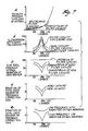
- Figure 7 is a series of graphical representations of data depicting closed feedback control loop operation for this invention.
- An interactive catalyst-fuel injector feedback system embodying the invention achieves unprecedented tight control of mean A/F ratio within a resolution of ± .01-.02% of stoichiometry in real time, such as within a response time of less than 60 milliseconds and the system compensates for degradation of the catalyst body or fuel system control over time that effects such accurate resolution and quickness of response in spite of variables of engine characteristics and degradation of the catalyst bodies or fuel system over time that effect such accurate resolution and quickness of response. This is achieved herein by a unique interactive combination of a small mass-volume filter catalyst and a linear, wide-range, multiple-cell, low mass exhaust gas oxygen sensor that is isolated from contamination and ambient temperature, the combination being positioned upstream of a conventional three-way catalyst body.
- As shown in Figure 1, the elements of a system for cleansing the gaseous emissions generated by the combustion within an internal combustion engine includes: an
engine 10 having a combustion chamber 11 and an A/F supply 12 comprising anair intake 15, an air throttle 17, an A/F meter 16, and a singlepoint fuel injector 13; anultrasonic fuel atomiser 14 may be used in some instances.Exhaust channels 18, from each of the combustion cylinders or chambers 11, lead and merge into acommon exhaust stream 19. Interposed in theexhaust stream 19 is a low mass-volume filter catalyst 20 located close to the point at which the exhaust channels merge into a common stream. A wide-range universal exhaust gas oxygen (UEGO)sensor 21 is located immediately downstream of the filter catalyst, and amain catalyst 22 is located downstream of thesensor 21. Interactive controls 23 in part are integral with the exhaust gas sensor construction and inpart link sensor 21 with thefuel injector 13 and other engine parameters in a closed loop feedback system. - The
filter catalyst 20 must be stationed in the emission stream with care and be structured to have a low mass-volume, three-way capability to filter out random combustion effects within the stream. Random combustion effects appear as turbulent rich and lean eddy currents contributed by the varying conditions of each individual combustion cylinder; the eddy currents represent a mixture of regular completed cylinder exhaust and incomplete cylinder combustion effects. The eddy currents are random. To operate as a filter and light-off catalyst, thecatalyst 20 should have a low mass of about 300-500 grams and a low volume of about 15-20 in³, which together will desirably filter frequencies higher than 10Hz. The filter catalyst should have a length which is relatively short, about 2-4 inches, if the cross-sectional configuration is circular. The filter catalyst should be designed to have a high space velocity (i.e., at least 50K/hr at engine idle and at least 350K/hr at wide-open throttle). The filter catalyst will represent only 10-20% of the total catalyst volume for the entire system (filter and main catalysts). Such catalyst may be supported on a monolithic structure having a cellular density of 200-400 cells per square inch, or may be a wire mesh support. - The ceramic cellular monolith type of support may operate in close coupled relationship to the exhaust manifold; a conventional washcoating may be used to stabilise the monolith for high temperature usage at such location. The filter catalyst should desirably be placed as close as possible to the source of the exhaust stream without damaging the effectiveness of the filter catalyst. In the preferred embodiment, such stationing is within 3-4 inches of the source of the emission stream 19 (location where cylinder exhausts merge as a unitary stream).
- The filter catalyst must have a heavy precious metal loading, particularly in the range of 40-60 gm/ft³ of precious metal. The precious metal may be comprised of platinum, palladium or rhodium, in combination or separately, to provide both oxidation and reduction of noxious elements within the emission stream, as is well known. It is important that such filter catalyst be capable of converting only a minor proportion (i.e., 40-60%) of noxious emission elements under heavy engine loading and up to 80-85% under idle conditions); this is brought about by controlling the mass, precious metal loading, size, and space velocity of the filter catalyst.
- Such filter catalyst will be capable of eliminating chemical noise because such noise has a high frequency well within the filtering capacity of such a small mass-volume aged or non-aged catalyst. The lowest anticipated chemical noise frequency emitted by the combustion cylinder is about 10Hz; this is well within the 4Hz filtering capacity of such catalyst. The conversion capability of such a new filter catalyst goes somewhat beyond removing random combustion effects for chemical noise because the filter catalyst design must allow for the inevitable ageing degradation of the catalyst.
- If the filter catalyst were designed to initially achieve greater conversion efficiencies than here specified, the response time of the entire feedback control system and sensor would be detrimentally affected because the control loop would be damped; a more damped and slower control loop frequency (limit cycle frequency) would permit larger A/F ratio excursions with resulting catalyst efficiency loss. Limit cycle frequency is the inverse of time taken to complete a rich to lean and back to rich control cycle. Limit cycle frequency is determined by the collective delays in the control loop and includes sensor response, gas transport delay, emission control electronics delays, and software algorithm delays.
- The essential characteristics required of a sensor to cooperate in the combination invention herein includes at least the basic Nernst-type electrochemical cell, often referred to as a switching exhaust gas oxygen sensor. Although this basic building block of the sensor is necessary, it is important that the final sensor not be of the switching type or step function, but include the refinements set forth herein.
- Application of sensors in the control of engine A/F ratio throughout the 1970's and 1980's have been essentially of the switchpoint type. These voltaic type ZrO₂ switchpoint sensors have been widely used [sometimes referred to as oxygen sensor, EGO (exhaust gas oxygen) sensor, HEGO (heated exhaust gas oxygen) sensor, electrochemical cell, lambda sensor, and fuel cell]. These sensors actually measure the partial pressure of oxygen in the exhaust produced by an engine; engine-out oxygen concentration is related to engine A/F ratio. When engine-out oxygen is measured with a gas analyser, there is no unique relationship between oxygen concentration and A/F ratio, especially at A/F ratio's near the stoichiometric ratio. It is use of catalytic materials in the sensor that promotes an equilibrated oxygen detection. However, the space velocity at a small sensor electrode is so great that little equilibration takes place in real engine operation. These sensors switch at stoichiometry, as predicted by the Nernst equation, only at fully equilibrated, stabilised, high temperature operation. Unfortunately, these conditions are never or rarely present in real engine operation as numerous SAE papers and patents indicate.
- The limitations of switchpoint oxygen sensors are: (a) their inability to accurately determine A/F ratio at accuracies greater than 1% and undesirable sensor response time as well as switching time; and (b) cannot measure transient deviations of A/F ratio close to stoichiometry resulting from such things as throttle movements or transmission shifts, without an increase in tailpipe emissions. Sensor response time is the time required for a sensor to establish equilibrium exhaust gas conditions at the electrode/electrolyte interface after a gas transition zone passes the sensor. Switching time is that time that a sensor takes to switch its voltage after establishment of gas equilibrium conditions at the interface. The two response times are frequently added together and described as the sensor response time. The response behaviour of the switchpoint sensor is complex and causes off-target adjustments. The voltage output of such sensor will wildly swing for each chemical variation occurring many times per second. These wild swings are usually filtered out by software in the microprocessor to swing once or twice per second. The microprocessor will transfer a signal to the fuel injector that is graduated at each swing but in the same direction as the voltage deviation. This results in a modification to the exhaust gas which compounds the chemical deviations with some slight reduction of the voltage peaks. Certain of the inadequacies is more fully discussed in U.S. patents 4,251,990 and 4,272,329.
- To overcome these limitations, the art has tried different arrangements such as numerous combinations of cell design arrangements, alternate up and downstream placement of sensor location, or forced use of algorithms. Location alone has not been able to solve the drift of the switchpoint sensor. Such attempts have not been able to improve "real time" feedback, but complicate the control system in return for a very small improvement in ageing drift control.
- The Nernst-type electrochemical cell includes (as shown in Figure 2) a
solid electrolyte 30 typically comprised of partially stabilised zirconia, which conducts oxygen ions betweenelectrodes 31, 32 (usually platinum) on its opposite sides withelectrode 31 exposed to air and theother electrode 32 exposed to exhaust gas. The electrodes are coated with protective spinel layers and these layers contribute to the sensor response slowness and complexity. An electromotive force (emf) is developed due to the difference in oxygen partial pressure in each of the air and exhaust gas. The voltage output V changes sharply at stoichiometric levels (an A/F ratio of 14.7), as shown in Figure 3. Such switchpoint type of exhaust gas sensor can only indicate when stoichiometry has been achieved, but it cannot tell you how lean or rich the A/F ratio is at any one point. Thus, even if such type of sensor were to be linearized, its basic function prevents it from achieving needed improvements in system control. - To eliminate this switchpoint characteristic, the sensor required for this invention (as shown in Figure 4) includes the additional elements of: (a)
dual cells 40, 41 (41 being the conventional Nernst-type sensing cell, and 40 being a pumping cell exhibiting a pumping current proportional to the A/F ratio); (b) a diffusion layer 43 (preferably supported on a plug) imposed between the two cells forms an aperture to control the quantity of oxygen molecules which arrive at the cavity between the cells while leaving theelectrodes 42 with no cating or covering [the aperture of this diffusion layer may be closed by a special porous diffusion layer to again control the steady arrival of oxygen molecules devoid of contamination effects]; (c) a reversingcircuit 44 to pump oxygen into a restricted volume between the two cells both during rich exhaust gas conditions and oxygen out of such restricted volume during lean exhaust gas conditions. This reversing circuit tends to maintain a stoichiometric mixture within the restricted volume between the cells. Thus, variation in time delays are avoided. Variability due to temperature conditions of the air or exhaust gas is eliminated by deploying embeddedheater elements cells - The sensing element cells have a low mass of less than five grams and the sensor provides ± 3% accuracy (of operating point) at lambdas of .7 and 1.4 with increasing accuracy toward lambda of 1 where it will be no more than ± .07%.
- The filter catalyst, sensor, and fuel injector must be interrelated to achieve a fast response time by selecting the closed loop gain (multiplying factor used on the sensor signal to apply adjustment power to the A/F ratio controller or fuel injector) and limit cycle frequency. The limit cycle frequency of the feedback control loop should be 3Hz or greater and the gain set 20% below normal to permit compensation for variability in the equipment and ageing of precious metal. Variability is used herein to mean variations within the fuel injector from engine to engine, variations in the sensor from system to system, and variations in air intake within the engine from cylinder to cylinder, and variation of burn rate within a single engine cylinder. Ageing is used herein to mean the poisoning or sintering of precious metals on the catalyst with the expiration of time. The gain and phase shift is shaped (i.e., by manipulating the capacitance and diffusion coefficient of the UEGO sensor) to make the sensor work with filter catalyst.
- The simplest interaction is to connect the sensor to the fuel injector in a direct proportional closed loop feedback while ensuring that the filter catalyst is sized and matched to the response of the sensor to provide only filtering (eliminate chemical noise) and convert a minor proportion of the noxious elements within the exhaust gas. Proportional means a continuous linear relation between output and input.
- It is, however, desirable that the primary feedback loop provide a proportional-integral (PI) control method, similar to a part of the controller described in the SAE technical publication by J. Ishii, M. Amano, T. Yamauchi, N. Kurihara, entitled "Wide-Range Air-Fuel Ratio Control System", Feb. 29, 1988 (SAE publication 880134) on in U.S. patent 3,939,654.
- Independent algorithms, whether proportional or integral, are used as loop gain coefficients in the control. The algorithms are dependent to sensor output behaviour. The proportional control algorithm acts in direct opposite and proportional direction to sensed A/F ratio of the UEGO sensor. The integral control algorithm integrates the A/F level for a period and acts to correct the mean A/F level for control system load, such as vapour purge load. Thus, proportional plus integral has the output proportional to a linear combination of the input and the time integral of the input. A typical PI algorithm would be:

where - b =
- proportional gain/static gain
- I =
- integral action rate
- P =
- proportional gain
- S =
- complex variable
- X =
- input transform
- Y =
- output transform
- Only P or PI control is necessary for this inventive control system. Thus, if the exhaust gas is in the rich region, the logic of the control method increases lambda, and if the exhaust gas is in the lean region, it will decrease lambda. In the closed loop arrangement (shown in Figure 6), injector power will be influenced by airflow and lambda as modified by injector coefficient Ki. PI feedback control is important because when used with a linear output UEGO sensor, the control algorithm will allow A/F ratio to stay at stoichiometry. Prior art algorithms do not allow this.
- To further improve the accuracy of A/F ratio control, an adaptive feedback loop may be further incorporated in addition to the primary feedback loop to provide corrections to the injector and open loop sensor coefficients for various airflow/speed combinations.
- The injector power is modified by open loop (feed forward) information obtained from temperature, speed of the engine, and engine load.
- To compensate for ageing of the system, the gain setting for the feedback loop must be arranged so that it is about 15-25% below that predetermined to normally amplify the expected signals received from the filter catalyst, taking into account the designed mass and size of such filter catalyst. Thus, when the filter catalyst is fresh, the millisecond amplitude variations in the A/F mixture entering the filter catalyst will be subdued upon exiting from such catalyst resulting from the elimination of chemical noise. The amplitude of such variations prior to passing the exhaust gas sensor will be subdued to normal and transient excursions. The sensor will then, with its quick response (.060 of a second phase shift), transmit a highly accurate voltage corresponding to the sensed amplitude, and the microprocessor will convert the voltage signal to an opposite value which changes the injector power function causing the A/F mixture being delivered to the filter catalyst to have reduced variation. The main three-way catalyst will then be more effective in converting the remainder of the noxious elements when the A/F ratio is relatively close to stoichiometry resulting in the final variation which almost assumes a straight line.
- When the filter catalyst is substantially aged, such as will occur at vehicle miles above 50,000, the amplitude of the A/F ratio will have exaggerated swings due to the inability of the filter catalyst to dampen such amplitudes and eliminate some of the chemical noise to the same degree as when fresh. The larger A/F ratio swings that occur past an aged filter catalyst act to increase feedback loop gain, thus increasing sensitivity. Also, the sensor will have, during the same time period, experienced some degradation which means that it will detect a lesser amount of the A/F ratio change. The degradation of the sensor acts to decrease the feedback loop gain to a lesser extent. Overall, the combined catalyst-sensor interaction will increase feedback loop gain with ageing thereby causing more rapid correction of A/F ratio deviations. An aged catalyst requires higher frequency and lower magnitude A/F ratio excursions to maintain high conversion efficiency.
- As shown in Figure 7a, O₂ rises very rapidly in excess of stoichiometry, but the conversion efficiency peaks at stoichiometry (see Figure 7b), such peaks being lower for the filter catalyst at high load than at idle, lower peaks for an aged catalyst compared to a fresh catalyst and lower peaks for a filter catalyst relative to a main catalyst. The variation in sensed O₂ will be less the closer to stoichiometry (Figure 7c). The correction gain of the aged filter catalyst is stronger than a fresh catalyst (7d).
- Thus, the closer the emission gas is to stoichiometry, the more it will be converted and the less be oxygen variations; the feedback correction gain in the microprocessor is less the closer the gas is to stoichiometry, but is increased by ageing as a result of the increase in amplitude of unfiltered chemical constituents (Figure 7E).
- Utilisation of the system of this invention can achieve, if not approach more closely, the anticipated federally mandated emissions for the year 2003.
Claims (10)
- A system for cleansing the gaseous emission stream generated by the combustion of an A/F mixture within cylinders of an internal combustion engine, the system comprising, a low mass, three-way filter catalyst (20) stationed close to the source of said stream effective to filter out random combustion effects within said stream, a high mass, three-way main catalyst (22) stationed downstream of said filter catalyst effective to convert the remainder of noxious emissions in said stream to desired levels, a continuous universal exhaust gas oxygen sensor (21) stationed in said stream between said catalysts effective to rapidly and accurately indicate the level of oxygen within the stream leaving the filter catalyst, and proportional control means (23) for adjusting in closed loop the A/F ratio of said mixture in interactive response to a deviation of the sensed oxygen level from a target level.
- A system as claimed in claim 1, in which said filter catalyst has a volume of less than 328cm³ (20 in³), and is loaded with precious metal in the range of 1430-2145 grams per m³ (40-60 grams per cubic foot).
- A system as claimed in claim 1, in which said filter catalyst is sized to have a length of 5-10cms (2-4 inches) and is separated from the source of the stream of said exhaust gas emissions by a distance of 2.5-10cm (1-4 inches).
- A system as claimed in claim 1, in which said main catalyst has a mass substantially greater than said filter catalyst and is loaded with precious metal in an amount no greater than 1430 gms/m³ (40 gm/ft³).
- A system as claimed in claim 1, in which said main catalyst is is stationed downstream from said filter catalyst a distance in the range of 2.5-15cms (1-6 inches)
- A system as claimed in claim 1, in which said sensor is comprised of: a Nernst-type electrochemical cell, a pumping cell, a reference chamber to which oxygen diffuses thereinto through a controlled channel said chamber being adjacent the cathode of each of said cells, a reversing circuit to pump oxygen into said chamber during rich exhaust gas conditions and out of such chamber during lean exhaust gas conditions thereby to maintain a stoichiometric mixture within such chamber, and an external heater to eliminate ambient temperature influences.
- An engine-catalyst control loop for cleansing the emission stream from said engine, comprising:(a) a main catalyst;(b) a filter starter catalyst upstream of said main catalyst and close coupled to the source of said exhaust stream;(c) a linear multiple-cell exhaust gas sensor positioned to sense the oxygen level of said stream intermediate said catalyst, said sensor having a symmetrical response and a response time less than 60 milliseconds;(d) controller means for adjustably introducing fuel and air as a mixture into said engine; and(e) electronic means for interactively connecting the output of said sensor with said controller means in a closed feedback loop, said electronic means being effective to provide at least proportional control of the A/F ratio with respect to said sensor output and can maintain the A/F ratio for said engine consistently at stoichiometry within an accuracy range of ± .01-.02% A/F.
- A control loop as claimed in claim 7, in which said electronic means receives input information with respect to other operating parameters of said engine and performs adaptive corrections to said proportional loop control in response to said parameters.
- A method of compensating for chemical ageing of a catalyst system used to cleanse, to a desired level, gaseous emissions from the combustion of an A/F mixture in cylinders of an internal combustion engine, said system being comprised of two in-line complementary loaded catalysts and a wide-range universal exhaust gas oxygen sensor interposed between such catalysts, the upstream catalyst being loaded to effect limited conversion of said noxious emissions and to filter out random combustion effects from the contents of said emissions, and an A/F controller interactively connected to the output voltage of said sensor in a closed loop feedback relationship to control the A/F mixture at or about stoichiometry within a desired accuracy range, the steps comprising:(a) empirically establishing the chemical degradation rate of said upstream catalyst with a predetermined type of usage that reduces conversion efficiency and permits greater gaseous noxious emissions to pass therethrough;(b) empirically establishing the degradation rate of said sensor with normal usage that reduces the gain of the sensor; and(c) establishing an initial gain characteristic for the interactive closed loop feedback that will increase in proportion to the empirically established rate of degradation of said upstream catalyst to offset any loss in sensitivity for said sensor as it degrades to maintain a substantially uniform level of conversion of the gaseous emissions from the downstream catalyst.
- A method as claimed in claim 9, in which in step (c) the gain of said feedback control loop is set 20% below that needed for normal sensing.
Applications Claiming Priority (2)
| Application Number | Priority Date | Filing Date | Title |
|---|---|---|---|
| US478398 | 1990-02-12 | ||
| US07/478,398 US5083427A (en) | 1990-02-12 | 1990-02-12 | Apparatus and method to reduce automotive emissions using filter catalyst interactive with uego |
Publications (2)
| Publication Number | Publication Date |
|---|---|
| EP0453062A1 true EP0453062A1 (en) | 1991-10-23 |
| EP0453062B1 EP0453062B1 (en) | 1994-12-21 |
Family
ID=23899784
Family Applications (1)
| Application Number | Title | Priority Date | Filing Date |
|---|---|---|---|
| EP91300628A Expired - Lifetime EP0453062B1 (en) | 1990-02-12 | 1991-01-28 | Apparatus and method to reduce automotive engine emissions |
Country Status (5)
| Country | Link |
|---|---|
| US (1) | US5083427A (en) |
| EP (1) | EP0453062B1 (en) |
| JP (1) | JPH0688520A (en) |
| CA (1) | CA2033400C (en) |
| DE (1) | DE69106029T2 (en) |
Cited By (3)
| Publication number | Priority date | Publication date | Assignee | Title |
|---|---|---|---|---|
| WO2004018858A3 (en) * | 2002-08-22 | 2004-09-02 | Volkswagen Ag | Internal combustion engine and method for operating an internal combustion engine comprising a fuel regulating device |
| EP1500926A1 (en) * | 2003-07-21 | 2005-01-26 | Vaillant GmbH | Method for the compensation of aging of a sensor for measuring a gas concentration |
| EP1788212A1 (en) * | 2004-09-09 | 2007-05-23 | Isuzu Motors Limited | Guide structure and exhaust emission control device |
Families Citing this family (41)
| Publication number | Priority date | Publication date | Assignee | Title |
|---|---|---|---|---|
| US5248859A (en) * | 1991-03-25 | 1993-09-28 | Alexander Borla | Collector/muffler/catalytic converter exhaust systems for evacuating internal combustion engine cylinders |
| JP3375645B2 (en) * | 1991-05-14 | 2003-02-10 | 株式会社日立製作所 | Control device for internal combustion engine |
| US5313791A (en) * | 1991-06-28 | 1994-05-24 | Ford Motor Company | Method for detecting catalyst malfunctions |
| CA2096382C (en) * | 1992-05-19 | 1998-05-05 | Ken Ogawa | Air-fuel ratio control system for internal combustion engines |
| US5535135A (en) * | 1993-08-24 | 1996-07-09 | Motorola, Inc. | State estimator based exhaust gas chemistry measurement system and method |
| US5351484A (en) * | 1993-12-16 | 1994-10-04 | Ford Motor Company | Light-off catalyst monitor |
| US5433071A (en) * | 1993-12-27 | 1995-07-18 | Ford Motor Company | Apparatus and method for controlling noxious components in automotive emissions using a conditioning catalyst for removing hydrogen |
| US5492612A (en) * | 1994-02-17 | 1996-02-20 | General Motors Corporation | Lean shift correction of potentiometric oxygen sensors |
| EP0668503A1 (en) * | 1994-02-17 | 1995-08-23 | General Motors Corporation | Catalytic/ceramic oxide microcomposite materials for use as exhaust sensor pre-equilibration zone |
| US6044644A (en) * | 1994-12-06 | 2000-04-04 | Engelhard Corporation | Close coupled catalyst |
| US6021639A (en) * | 1995-06-28 | 2000-02-08 | Mitsubishi Heavy Industries, Ltd. | Black smoke eliminating device for internal combustion engine and exhaust gas cleaning system including the device |
| US5846502A (en) * | 1996-01-16 | 1998-12-08 | Ford Global Technologies, Inc. | Mini-cascade catalyst system |
| JP3729295B2 (en) * | 1996-08-29 | 2005-12-21 | 本田技研工業株式会社 | Air-fuel ratio control device for internal combustion engine |
| DE19826284B4 (en) * | 1997-06-19 | 2009-07-30 | Volkswagen Ag | Arrangement for a vehicle exhaust system with catalytic converter |
| US5848528A (en) * | 1997-08-13 | 1998-12-15 | Siemens Automotive Corporation | Optimization of closed-loop and post O2 fuel control by measuring catalyst oxygen storage capacity |
| US7127883B1 (en) * | 1997-11-10 | 2006-10-31 | Mitsubishi Jidosha Kogoyo Kabushiki Kaisha | Exhaust gas purifying apparatus of internal combustion engine |
| US6052989A (en) * | 1998-01-23 | 2000-04-25 | Ford Global Technologies, Inc. | Emission control system for internal combustion engines |
| US6138452A (en) * | 1999-03-05 | 2000-10-31 | Ford Global Technologies, Inc. | Catalytic monitoring method |
| US6365108B1 (en) * | 1999-10-12 | 2002-04-02 | Caterpillar Inc. | Siloxane filter for O2 sensor for bio-gas engine |
| US7090806B1 (en) * | 2000-05-01 | 2006-08-15 | Peter Lenehan | Portable oxygen sensor analyzer |
| JP3824959B2 (en) * | 2002-03-29 | 2006-09-20 | 本田技研工業株式会社 | Exhaust gas sensor temperature control device |
| JP3957180B2 (en) * | 2002-08-09 | 2007-08-15 | 本田技研工業株式会社 | Air-fuel ratio control apparatus for internal combustion engine using decimation filter |
| US6865472B2 (en) * | 2002-09-27 | 2005-03-08 | Horiba Ltd. | Vehicle-installed exhaust gas analyzing apparatus |
| US7137382B2 (en) * | 2002-11-01 | 2006-11-21 | Visteon Global Technologies, Inc. | Optimal wide open throttle air/fuel ratio control |
| WO2004059151A1 (en) * | 2002-12-30 | 2004-07-15 | Volkswagen Ag | Method and device for adjusting the fuel/ air ratio in an internal combustion engine |
| WO2005005797A2 (en) * | 2003-06-12 | 2005-01-20 | Donaldson Company, Inc. | Method of dispensing fuel into transient flow of an exhaust system |
| DE102004027907A1 (en) * | 2004-06-09 | 2005-12-29 | Emitec Gesellschaft Für Emissionstechnologie Mbh | Control system for a mobile internal combustion engine |
| JP4392315B2 (en) * | 2004-09-30 | 2009-12-24 | 本田技研工業株式会社 | Arrangement structure of air-fuel ratio sensor in motorcycle |
| JP2006097605A (en) * | 2004-09-30 | 2006-04-13 | Honda Motor Co Ltd | Arrangement structure of air-fuel ratio sensor in motorcycle |
| US20060101810A1 (en) * | 2004-11-15 | 2006-05-18 | Angelo Theodore G | System for dispensing fuel into an exhaust system of a diesel engine |
| US7234455B2 (en) * | 2005-09-02 | 2007-06-26 | Ford Global Technologies, Llc | Robust maximum engine torque estimation |
| US7581390B2 (en) * | 2006-04-26 | 2009-09-01 | Cummins Inc. | Method and system for improving sensor accuracy |
| US8302496B2 (en) | 2006-06-03 | 2012-11-06 | Eldon James Corporation | Universal sensor fitting for process applications |
| US20080053070A1 (en) * | 2006-09-01 | 2008-03-06 | Andrew Hatton | Apparatus and method for regenerating a particulate filter with a non-uniformly loaded oxidation catalyst |
| US8079351B2 (en) * | 2008-01-10 | 2011-12-20 | Ford Global Technologies, Llc | Temperature sensor diagnostics |
| US8448424B2 (en) * | 2009-01-16 | 2013-05-28 | Ford Global Technologies, Llc. | Emission control system with an integrated particulate filter and selective catalytic reduction unit |
| US20110064632A1 (en) * | 2009-09-14 | 2011-03-17 | Ford Global Technologies, Llc | Staged Catalyst System and Method of Using the Same |
| DE102013208721A1 (en) * | 2012-06-12 | 2013-12-12 | Ford Global Technologies, Llc | Method and device for operating an internal combustion engine |
| JP5738249B2 (en) | 2012-09-13 | 2015-06-17 | 本田技研工業株式会社 | Exhaust gas purification system for internal combustion engine |
| US20150231617A1 (en) * | 2014-02-19 | 2015-08-20 | Ford Global Technologies, Llc | Fe-SAPO-34 CATALYST FOR USE IN NOX REDUCTION AND METHOD OF MAKING |
| US10422292B2 (en) * | 2017-03-27 | 2019-09-24 | Ford Global Technologies, Llc | Methods and systems for an exhaust oxygen sensor operation |
Citations (1)
| Publication number | Priority date | Publication date | Assignee | Title |
|---|---|---|---|---|
| EP0420462A2 (en) * | 1989-09-28 | 1991-04-03 | Rover Group Limited | A catalytic converter |
Family Cites Families (12)
| Publication number | Priority date | Publication date | Assignee | Title |
|---|---|---|---|---|
| DE2401417C2 (en) * | 1974-01-12 | 1981-10-01 | Robert Bosch Gmbh, 7000 Stuttgart | Process for detoxifying the exhaust gases of an internal combustion engine |
| DE2505339C2 (en) * | 1975-02-08 | 1984-08-09 | Daimler-Benz Ag, 7000 Stuttgart | Mixture-compressing internal combustion engine with two rows of cylinders and exhaust gas aftertreatment |
| US3939654A (en) * | 1975-02-11 | 1976-02-24 | General Motors Corporation | Engine with dual sensor closed loop fuel control |
| JPS5239027A (en) * | 1975-09-22 | 1977-03-26 | Hitachi Ltd | A feedback controlled exhaust purification device |
| JPS5858848B2 (en) * | 1976-06-24 | 1983-12-27 | ソニー株式会社 | heterodyne receiver |
| JPS5417414A (en) * | 1977-07-08 | 1979-02-08 | Nippon Soken Inc | Exhaust gas purifying system |
| JPS5535181A (en) * | 1978-09-05 | 1980-03-12 | Nippon Denso Co Ltd | Air fuel ratio control device |
| DE2937802C2 (en) * | 1979-09-19 | 1987-02-19 | Degussa Ag, 6000 Frankfurt | Improved probe for measuring the oxygen content in the exhaust gas of internal combustion engines |
| US4272329A (en) * | 1980-03-03 | 1981-06-09 | Ford Motor Company | Steady state mode oxygen sensor and method |
| JPS6260941A (en) * | 1985-09-10 | 1987-03-17 | Toyota Motor Corp | Air-fuel ratio controller for internal combustion engine |
| JPS62182645A (en) * | 1985-12-26 | 1987-08-11 | Honda Motor Co Ltd | Method for controlling oxygen concentration sensor |
| US4841934A (en) * | 1987-02-20 | 1989-06-27 | Ford Motor Company | Oxygen pumping device for control of the air fuel ratio |
-
1990
- 1990-02-12 US US07/478,398 patent/US5083427A/en not_active Expired - Lifetime
- 1990-12-28 CA CA002033400A patent/CA2033400C/en not_active Expired - Fee Related
-
1991
- 1991-01-28 EP EP91300628A patent/EP0453062B1/en not_active Expired - Lifetime
- 1991-01-28 DE DE69106029T patent/DE69106029T2/en not_active Expired - Fee Related
- 1991-02-06 JP JP3015298A patent/JPH0688520A/en active Pending
Patent Citations (1)
| Publication number | Priority date | Publication date | Assignee | Title |
|---|---|---|---|---|
| EP0420462A2 (en) * | 1989-09-28 | 1991-04-03 | Rover Group Limited | A catalytic converter |
Non-Patent Citations (4)
| Title |
|---|
| PATENT ABSTRACTS OF JAPAN, vol. 13, no. 244 (M-834), 7th June 1989; & JP-A-1-053 038 (MITSUBISHI) 10-03-1089 * |
| PATENT ABSTRACTS OF JAPAN, vol. 13, no. 244 (M-834), 7th June 1989; & JP-A-1-053 042 (MITSUBSHI) 01-03-1989 * |
| PATENT ABSTRACTS OF JAPAN, vol. 3, no. 97 (M-69), 17th August 1979; & JP-A-54-071 225 (NISSAN) 07-06-1979 * |
| PATENT ABSTRACTS OF JAPAN, vol. 4, no. 37 (M-4), 27th March 1980; & JP-A-55-010 043 (SUZUKI) 24-01.1980 * |
Cited By (5)
| Publication number | Priority date | Publication date | Assignee | Title |
|---|---|---|---|---|
| WO2004018858A3 (en) * | 2002-08-22 | 2004-09-02 | Volkswagen Ag | Internal combustion engine and method for operating an internal combustion engine comprising a fuel regulating device |
| EP1500926A1 (en) * | 2003-07-21 | 2005-01-26 | Vaillant GmbH | Method for the compensation of aging of a sensor for measuring a gas concentration |
| EP1788212A1 (en) * | 2004-09-09 | 2007-05-23 | Isuzu Motors Limited | Guide structure and exhaust emission control device |
| EP1788212A4 (en) * | 2004-09-09 | 2010-05-26 | Isuzu Motors Ltd | Guide structure and exhaust emission control device |
| US7963109B2 (en) | 2004-09-09 | 2011-06-21 | Isuzu Motors Limited | Guide structure and exhaust gas purification device |
Also Published As
| Publication number | Publication date |
|---|---|
| CA2033400A1 (en) | 1991-08-13 |
| JPH0688520A (en) | 1994-03-29 |
| EP0453062B1 (en) | 1994-12-21 |
| US5083427A (en) | 1992-01-28 |
| CA2033400C (en) | 2000-12-12 |
| DE69106029T2 (en) | 1995-05-04 |
| DE69106029D1 (en) | 1995-02-02 |
Similar Documents
| Publication | Publication Date | Title |
|---|---|---|
| EP0453062B1 (en) | Apparatus and method to reduce automotive engine emissions | |
| US7124013B2 (en) | Control device, control method, control unit, and engine control unit | |
| US5791139A (en) | Fuel injection control method for an internal-combustion engine provided with NOx reducing catalytic converter and fuel injection controller | |
| EP0799985A3 (en) | Air-fuel ratio control system for internal combustion engines | |
| JPH06146865A (en) | Catalyst deterioration judgment device for internal combustion engine | |
| EP0851108B1 (en) | Air-fuel detection system using a limit current sensor | |
| US4580539A (en) | Air-fuel ratio control apparatus | |
| JP3805408B2 (en) | Air-fuel ratio control device for internal combustion engine | |
| US5417060A (en) | Air fuel ratio control apparatus for an internal combustion engine | |
| JPH0331546A (en) | Air-fuel ratio controller for internal combustion engine | |
| US6153071A (en) | Exhaust oxygen sensing | |
| US6161376A (en) | Method and apparatus for controlling air-fuel ratio of internal combustion engine | |
| JP3420932B2 (en) | Method for detecting element resistance of gas concentration sensor | |
| JPS6133981B2 (en) | ||
| US6103098A (en) | Method of sensing exhaust oxygen | |
| US11174808B2 (en) | Air-fuel ratio control system and air-fuel ratio control method | |
| JPS6254973B2 (en) | ||
| JP2518254B2 (en) | Air-fuel ratio control device for internal combustion engine | |
| JP2917431B2 (en) | Exhaust gas purification device for internal combustion engine | |
| JP2560303B2 (en) | Air-fuel ratio control device for internal combustion engine | |
| JPH0617660B2 (en) | Air-fuel ratio controller for internal combustion engine | |
| JPH089390Y2 (en) | Air-fuel ratio feedback control system for internal combustion engine | |
| JP2596009B2 (en) | Air-fuel ratio control device for internal combustion engine | |
| JP2600767B2 (en) | Air-fuel ratio control device for internal combustion engine | |
| JPH08105343A (en) | Method for evaluating characteristic of exhaust gas sensor of internal combustion engine |
Legal Events
| Date | Code | Title | Description |
|---|---|---|---|
| PUAI | Public reference made under article 153(3) epc to a published international application that has entered the european phase |
Free format text: ORIGINAL CODE: 0009012 |
|
| AK | Designated contracting states |
Kind code of ref document: A1 Designated state(s): DE FR GB |
|
| 17P | Request for examination filed |
Effective date: 19920331 |
|
| 17Q | First examination report despatched |
Effective date: 19930205 |
|
| GRAA | (expected) grant |
Free format text: ORIGINAL CODE: 0009210 |
|
| AK | Designated contracting states |
Kind code of ref document: B1 Designated state(s): DE FR GB |
|
| REF | Corresponds to: |
Ref document number: 69106029 Country of ref document: DE Date of ref document: 19950202 |
|
| ET | Fr: translation filed | ||
| PLBE | No opposition filed within time limit |
Free format text: ORIGINAL CODE: 0009261 |
|
| STAA | Information on the status of an ep patent application or granted ep patent |
Free format text: STATUS: NO OPPOSITION FILED WITHIN TIME LIMIT |
|
| 26N | No opposition filed | ||
| REG | Reference to a national code |
Ref country code: GB Ref legal event code: 746 Effective date: 19951214 |
|
| REG | Reference to a national code |
Ref country code: FR Ref legal event code: D9 Free format text: CORRECTION |
|
| REG | Reference to a national code |
Ref country code: FR Ref legal event code: TP Ref country code: FR Ref legal event code: CD |
|
| PGFP | Annual fee paid to national office [announced via postgrant information from national office to epo] |
Ref country code: DE Payment date: 20010102 Year of fee payment: 11 |
|
| PGFP | Annual fee paid to national office [announced via postgrant information from national office to epo] |
Ref country code: GB Payment date: 20010115 Year of fee payment: 11 |
|
| PGFP | Annual fee paid to national office [announced via postgrant information from national office to epo] |
Ref country code: FR Payment date: 20010124 Year of fee payment: 11 |
|
| REG | Reference to a national code |
Ref country code: GB Ref legal event code: IF02 |
|
| PG25 | Lapsed in a contracting state [announced via postgrant information from national office to epo] |
Ref country code: GB Free format text: LAPSE BECAUSE OF NON-PAYMENT OF DUE FEES Effective date: 20020128 |
|
| PG25 | Lapsed in a contracting state [announced via postgrant information from national office to epo] |
Ref country code: DE Free format text: LAPSE BECAUSE OF NON-PAYMENT OF DUE FEES Effective date: 20020801 |
|
| GBPC | Gb: european patent ceased through non-payment of renewal fee |
Effective date: 20020128 |
|
| PG25 | Lapsed in a contracting state [announced via postgrant information from national office to epo] |
Ref country code: FR Free format text: LAPSE BECAUSE OF NON-PAYMENT OF DUE FEES Effective date: 20020930 |
|
| REG | Reference to a national code |
Ref country code: FR Ref legal event code: ST |