EP0452880B1 - Delivery member and apparatus making use of it - Google Patents
Delivery member and apparatus making use of it Download PDFInfo
- Publication number
- EP0452880B1 EP0452880B1 EP19910106047 EP91106047A EP0452880B1 EP 0452880 B1 EP0452880 B1 EP 0452880B1 EP 19910106047 EP19910106047 EP 19910106047 EP 91106047 A EP91106047 A EP 91106047A EP 0452880 B1 EP0452880 B1 EP 0452880B1
- Authority
- EP
- European Patent Office
- Prior art keywords
- electro
- deposition
- coating film
- coated
- weight
- Prior art date
- Legal status (The legal status is an assumption and is not a legal conclusion. Google has not performed a legal analysis and makes no representation as to the accuracy of the status listed.)
- Expired - Lifetime
Links
- 238000004070 electrodeposition Methods 0.000 claims description 146
- 238000000576 coating method Methods 0.000 claims description 142
- 239000011248 coating agent Substances 0.000 claims description 140
- 239000000843 powder Substances 0.000 claims description 105
- 239000002245 particle Substances 0.000 claims description 66
- 239000000919 ceramic Substances 0.000 claims description 26
- 229910052751 metal Inorganic materials 0.000 claims description 25
- 239000002184 metal Substances 0.000 claims description 25
- 238000000034 method Methods 0.000 claims description 21
- 238000004519 manufacturing process Methods 0.000 claims description 20
- 229920005989 resin Polymers 0.000 claims description 10
- 239000011347 resin Substances 0.000 claims description 10
- 239000000976 ink Substances 0.000 claims description 5
- 239000000758 substrate Substances 0.000 claims description 5
- 238000001962 electrophoresis Methods 0.000 claims description 4
- 239000000203 mixture Substances 0.000 claims description 3
- 239000003086 colorant Substances 0.000 claims description 2
- 238000012360 testing method Methods 0.000 description 66
- PXHVJJICTQNCMI-UHFFFAOYSA-N nickel Substances [Ni] PXHVJJICTQNCMI-UHFFFAOYSA-N 0.000 description 49
- 239000008199 coating composition Substances 0.000 description 48
- 230000003068 static effect Effects 0.000 description 46
- XLYOFNOQVPJJNP-UHFFFAOYSA-N water Substances O XLYOFNOQVPJJNP-UHFFFAOYSA-N 0.000 description 36
- 239000000463 material Substances 0.000 description 24
- 238000000151 deposition Methods 0.000 description 20
- 230000008021 deposition Effects 0.000 description 20
- 229920000877 Melamine resin Polymers 0.000 description 18
- 239000006185 dispersion Substances 0.000 description 18
- DHQIYHHEPUYAAX-UHFFFAOYSA-N n-(4,6-diamino-1,3,5-triazin-2-yl)prop-2-enamide Chemical compound NC1=NC(N)=NC(NC(=O)C=C)=N1 DHQIYHHEPUYAAX-UHFFFAOYSA-N 0.000 description 18
- 229910052759 nickel Inorganic materials 0.000 description 18
- 239000004640 Melamine resin Substances 0.000 description 17
- 229910000831 Steel Inorganic materials 0.000 description 17
- 229910052782 aluminium Inorganic materials 0.000 description 17
- XAGFODPZIPBFFR-UHFFFAOYSA-N aluminium Chemical compound [Al] XAGFODPZIPBFFR-UHFFFAOYSA-N 0.000 description 17
- 238000001723 curing Methods 0.000 description 17
- 238000007772 electroless plating Methods 0.000 description 17
- 235000012907 honey Nutrition 0.000 description 17
- 239000010959 steel Substances 0.000 description 17
- 230000000694 effects Effects 0.000 description 16
- 229910001220 stainless steel Inorganic materials 0.000 description 16
- 239000010935 stainless steel Substances 0.000 description 16
- PNEYBMLMFCGWSK-UHFFFAOYSA-N aluminium oxide Inorganic materials [O-2].[O-2].[O-2].[Al+3].[Al+3] PNEYBMLMFCGWSK-UHFFFAOYSA-N 0.000 description 15
- 229910052593 corundum Inorganic materials 0.000 description 15
- 239000007787 solid Substances 0.000 description 15
- 229910001845 yogo sapphire Inorganic materials 0.000 description 15
- TWNQGVIAIRXVLR-UHFFFAOYSA-N oxo(oxoalumanyloxy)alumane Chemical compound O=[Al]O[Al]=O TWNQGVIAIRXVLR-UHFFFAOYSA-N 0.000 description 14
- 229920000122 acrylonitrile butadiene styrene Polymers 0.000 description 11
- 229920003023 plastic Polymers 0.000 description 9
- 239000004033 plastic Substances 0.000 description 9
- VYPSYNLAJGMNEJ-UHFFFAOYSA-N Silicium dioxide Chemical compound O=[Si]=O VYPSYNLAJGMNEJ-UHFFFAOYSA-N 0.000 description 8
- 239000010949 copper Substances 0.000 description 8
- 238000007747 plating Methods 0.000 description 8
- 230000008859 change Effects 0.000 description 7
- 238000011282 treatment Methods 0.000 description 7
- 239000004925 Acrylic resin Substances 0.000 description 6
- 229920000178 Acrylic resin Polymers 0.000 description 6
- 238000004140 cleaning Methods 0.000 description 6
- 238000011109 contamination Methods 0.000 description 6
- 229920001971 elastomer Polymers 0.000 description 6
- 230000000704 physical effect Effects 0.000 description 6
- 238000005406 washing Methods 0.000 description 6
- 229910052802 copper Inorganic materials 0.000 description 5
- VZSRBBMJRBPUNF-UHFFFAOYSA-N 2-(2,3-dihydro-1H-inden-2-ylamino)-N-[3-oxo-3-(2,4,6,7-tetrahydrotriazolo[4,5-c]pyridin-5-yl)propyl]pyrimidine-5-carboxamide Chemical compound C1C(CC2=CC=CC=C12)NC1=NC=C(C=N1)C(=O)NCCC(N1CC2=C(CC1)NN=N2)=O VZSRBBMJRBPUNF-UHFFFAOYSA-N 0.000 description 4
- 125000000129 anionic group Chemical group 0.000 description 4
- 229910052681 coesite Inorganic materials 0.000 description 4
- 238000007739 conversion coating Methods 0.000 description 4
- 229910052906 cristobalite Inorganic materials 0.000 description 4
- 238000002156 mixing Methods 0.000 description 4
- 239000000377 silicon dioxide Substances 0.000 description 4
- 229910052682 stishovite Inorganic materials 0.000 description 4
- 239000000126 substance Substances 0.000 description 4
- 229910052905 tridymite Inorganic materials 0.000 description 4
- RYGMFSIKBFXOCR-UHFFFAOYSA-N Copper Chemical compound [Cu] RYGMFSIKBFXOCR-UHFFFAOYSA-N 0.000 description 3
- XEEYBQQBJWHFJM-UHFFFAOYSA-N Iron Chemical compound [Fe] XEEYBQQBJWHFJM-UHFFFAOYSA-N 0.000 description 3
- 229920006362 Teflon® Polymers 0.000 description 3
- 239000003513 alkali Substances 0.000 description 3
- 238000007743 anodising Methods 0.000 description 3
- 125000002091 cationic group Chemical group 0.000 description 3
- 239000010941 cobalt Substances 0.000 description 3
- 229910017052 cobalt Inorganic materials 0.000 description 3
- GUTLYIVDDKVIGB-UHFFFAOYSA-N cobalt atom Chemical compound [Co] GUTLYIVDDKVIGB-UHFFFAOYSA-N 0.000 description 3
- 239000002131 composite material Substances 0.000 description 3
- 238000005520 cutting process Methods 0.000 description 3
- 239000013527 degreasing agent Substances 0.000 description 3
- 229910003460 diamond Inorganic materials 0.000 description 3
- 239000010432 diamond Substances 0.000 description 3
- 238000001035 drying Methods 0.000 description 3
- 239000000945 filler Substances 0.000 description 3
- 239000010419 fine particle Substances 0.000 description 3
- 229910000398 iron phosphate Inorganic materials 0.000 description 3
- WBJZTOZJJYAKHQ-UHFFFAOYSA-K iron(3+) phosphate Chemical compound [Fe+3].[O-]P([O-])([O-])=O WBJZTOZJJYAKHQ-UHFFFAOYSA-K 0.000 description 3
- 230000007246 mechanism Effects 0.000 description 3
- 230000003647 oxidation Effects 0.000 description 3
- 238000007254 oxidation reaction Methods 0.000 description 3
- KDLHZDBZIXYQEI-UHFFFAOYSA-N palladium Substances [Pd] KDLHZDBZIXYQEI-UHFFFAOYSA-N 0.000 description 3
- 230000003746 surface roughness Effects 0.000 description 3
- 239000010936 titanium Substances 0.000 description 3
- HMUNWXXNJPVALC-UHFFFAOYSA-N 1-[4-[2-(2,3-dihydro-1H-inden-2-ylamino)pyrimidin-5-yl]piperazin-1-yl]-2-(2,4,6,7-tetrahydrotriazolo[4,5-c]pyridin-5-yl)ethanone Chemical compound C1C(CC2=CC=CC=C12)NC1=NC=C(C=N1)N1CCN(CC1)C(CN1CC2=C(CC1)NN=N2)=O HMUNWXXNJPVALC-UHFFFAOYSA-N 0.000 description 2
- WZFUQSJFWNHZHM-UHFFFAOYSA-N 2-[4-[2-(2,3-dihydro-1H-inden-2-ylamino)pyrimidin-5-yl]piperazin-1-yl]-1-(2,4,6,7-tetrahydrotriazolo[4,5-c]pyridin-5-yl)ethanone Chemical compound C1C(CC2=CC=CC=C12)NC1=NC=C(C=N1)N1CCN(CC1)CC(=O)N1CC2=C(CC1)NN=N2 WZFUQSJFWNHZHM-UHFFFAOYSA-N 0.000 description 2
- IHCCLXNEEPMSIO-UHFFFAOYSA-N 2-[4-[2-(2,3-dihydro-1H-inden-2-ylamino)pyrimidin-5-yl]piperidin-1-yl]-1-(2,4,6,7-tetrahydrotriazolo[4,5-c]pyridin-5-yl)ethanone Chemical compound C1C(CC2=CC=CC=C12)NC1=NC=C(C=N1)C1CCN(CC1)CC(=O)N1CC2=C(CC1)NN=N2 IHCCLXNEEPMSIO-UHFFFAOYSA-N 0.000 description 2
- VEXZGXHMUGYJMC-UHFFFAOYSA-N Hydrochloric acid Chemical compound Cl VEXZGXHMUGYJMC-UHFFFAOYSA-N 0.000 description 2
- NIPNSKYNPDTRPC-UHFFFAOYSA-N N-[2-oxo-2-(2,4,6,7-tetrahydrotriazolo[4,5-c]pyridin-5-yl)ethyl]-2-[[3-(trifluoromethoxy)phenyl]methylamino]pyrimidine-5-carboxamide Chemical compound O=C(CNC(=O)C=1C=NC(=NC=1)NCC1=CC(=CC=C1)OC(F)(F)F)N1CC2=C(CC1)NN=N2 NIPNSKYNPDTRPC-UHFFFAOYSA-N 0.000 description 2
- AFCARXCZXQIEQB-UHFFFAOYSA-N N-[3-oxo-3-(2,4,6,7-tetrahydrotriazolo[4,5-c]pyridin-5-yl)propyl]-2-[[3-(trifluoromethoxy)phenyl]methylamino]pyrimidine-5-carboxamide Chemical compound O=C(CCNC(=O)C=1C=NC(=NC=1)NCC1=CC(=CC=C1)OC(F)(F)F)N1CC2=C(CC1)NN=N2 AFCARXCZXQIEQB-UHFFFAOYSA-N 0.000 description 2
- 229910052581 Si3N4 Inorganic materials 0.000 description 2
- 239000004809 Teflon Substances 0.000 description 2
- WGLPBDUCMAPZCE-UHFFFAOYSA-N Trioxochromium Chemical compound O=[Cr](=O)=O WGLPBDUCMAPZCE-UHFFFAOYSA-N 0.000 description 2
- 239000002585 base Substances 0.000 description 2
- 230000015572 biosynthetic process Effects 0.000 description 2
- 239000011247 coating layer Substances 0.000 description 2
- 239000011231 conductive filler Substances 0.000 description 2
- 238000005260 corrosion Methods 0.000 description 2
- 230000007797 corrosion Effects 0.000 description 2
- 238000010586 diagram Methods 0.000 description 2
- QDOXWKRWXJOMAK-UHFFFAOYSA-N dichromium trioxide Chemical compound O=[Cr]O[Cr]=O QDOXWKRWXJOMAK-UHFFFAOYSA-N 0.000 description 2
- 239000000428 dust Substances 0.000 description 2
- 238000007590 electrostatic spraying Methods 0.000 description 2
- 238000009413 insulation Methods 0.000 description 2
- 229910052742 iron Inorganic materials 0.000 description 2
- JEIPFZHSYJVQDO-UHFFFAOYSA-N iron(III) oxide Inorganic materials O=[Fe]O[Fe]=O JEIPFZHSYJVQDO-UHFFFAOYSA-N 0.000 description 2
- 239000010410 layer Substances 0.000 description 2
- 238000005259 measurement Methods 0.000 description 2
- 238000000465 moulding Methods 0.000 description 2
- 230000003287 optical effect Effects 0.000 description 2
- 229910052763 palladium Inorganic materials 0.000 description 2
- 230000008569 process Effects 0.000 description 2
- 238000005488 sandblasting Methods 0.000 description 2
- 229910052709 silver Inorganic materials 0.000 description 2
- 239000007921 spray Substances 0.000 description 2
- WFKWXMTUELFFGS-UHFFFAOYSA-N tungsten Chemical compound [W] WFKWXMTUELFFGS-UHFFFAOYSA-N 0.000 description 2
- 229910052721 tungsten Inorganic materials 0.000 description 2
- 239000010937 tungsten Substances 0.000 description 2
- TXUICONDJPYNPY-UHFFFAOYSA-N (1,10,13-trimethyl-3-oxo-4,5,6,7,8,9,11,12,14,15,16,17-dodecahydrocyclopenta[a]phenanthren-17-yl) heptanoate Chemical compound C1CC2CC(=O)C=C(C)C2(C)C2C1C1CCC(OC(=O)CCCCCC)C1(C)CC2 TXUICONDJPYNPY-UHFFFAOYSA-N 0.000 description 1
- OHVLMTFVQDZYHP-UHFFFAOYSA-N 1-(2,4,6,7-tetrahydrotriazolo[4,5-c]pyridin-5-yl)-2-[4-[2-[[3-(trifluoromethoxy)phenyl]methylamino]pyrimidin-5-yl]piperazin-1-yl]ethanone Chemical compound N1N=NC=2CN(CCC=21)C(CN1CCN(CC1)C=1C=NC(=NC=1)NCC1=CC(=CC=C1)OC(F)(F)F)=O OHVLMTFVQDZYHP-UHFFFAOYSA-N 0.000 description 1
- LDXJRKWFNNFDSA-UHFFFAOYSA-N 2-(2,4,6,7-tetrahydrotriazolo[4,5-c]pyridin-5-yl)-1-[4-[2-[[3-(trifluoromethoxy)phenyl]methylamino]pyrimidin-5-yl]piperazin-1-yl]ethanone Chemical compound C1CN(CC2=NNN=C21)CC(=O)N3CCN(CC3)C4=CN=C(N=C4)NCC5=CC(=CC=C5)OC(F)(F)F LDXJRKWFNNFDSA-UHFFFAOYSA-N 0.000 description 1
- YLZOPXRUQYQQID-UHFFFAOYSA-N 3-(2,4,6,7-tetrahydrotriazolo[4,5-c]pyridin-5-yl)-1-[4-[2-[[3-(trifluoromethoxy)phenyl]methylamino]pyrimidin-5-yl]piperazin-1-yl]propan-1-one Chemical compound N1N=NC=2CN(CCC=21)CCC(=O)N1CCN(CC1)C=1C=NC(=NC=1)NCC1=CC(=CC=C1)OC(F)(F)F YLZOPXRUQYQQID-UHFFFAOYSA-N 0.000 description 1
- DEXFNLNNUZKHNO-UHFFFAOYSA-N 6-[3-[4-[2-(2,3-dihydro-1H-inden-2-ylamino)pyrimidin-5-yl]piperidin-1-yl]-3-oxopropyl]-3H-1,3-benzoxazol-2-one Chemical compound C1C(CC2=CC=CC=C12)NC1=NC=C(C=N1)C1CCN(CC1)C(CCC1=CC2=C(NC(O2)=O)C=C1)=O DEXFNLNNUZKHNO-UHFFFAOYSA-N 0.000 description 1
- ZOKXTWBITQBERF-UHFFFAOYSA-N Molybdenum Chemical compound [Mo] ZOKXTWBITQBERF-UHFFFAOYSA-N 0.000 description 1
- 229910019802 NbC Inorganic materials 0.000 description 1
- BQCADISMDOOEFD-UHFFFAOYSA-N Silver Chemical compound [Ag] BQCADISMDOOEFD-UHFFFAOYSA-N 0.000 description 1
- 229910021626 Tin(II) chloride Inorganic materials 0.000 description 1
- RTAQQCXQSZGOHL-UHFFFAOYSA-N Titanium Chemical compound [Ti] RTAQQCXQSZGOHL-UHFFFAOYSA-N 0.000 description 1
- GEIAQOFPUVMAGM-UHFFFAOYSA-N ZrO Inorganic materials [Zr]=O GEIAQOFPUVMAGM-UHFFFAOYSA-N 0.000 description 1
- 239000006096 absorbing agent Substances 0.000 description 1
- 238000010521 absorption reaction Methods 0.000 description 1
- 230000009471 action Effects 0.000 description 1
- 239000000654 additive Substances 0.000 description 1
- 230000000996 additive effect Effects 0.000 description 1
- 238000005054 agglomeration Methods 0.000 description 1
- 230000002776 aggregation Effects 0.000 description 1
- 229920000180 alkyd Polymers 0.000 description 1
- QHIWVLPBUQWDMQ-UHFFFAOYSA-N butyl prop-2-enoate;methyl 2-methylprop-2-enoate;prop-2-enoic acid Chemical compound OC(=O)C=C.COC(=O)C(C)=C.CCCCOC(=O)C=C QHIWVLPBUQWDMQ-UHFFFAOYSA-N 0.000 description 1
- 230000003197 catalytic effect Effects 0.000 description 1
- 238000006243 chemical reaction Methods 0.000 description 1
- 239000000470 constituent Substances 0.000 description 1
- 238000009792 diffusion process Methods 0.000 description 1
- 238000007865 diluting Methods 0.000 description 1
- 238000009826 distribution Methods 0.000 description 1
- 230000003028 elevating effect Effects 0.000 description 1
- 230000008030 elimination Effects 0.000 description 1
- 238000003379 elimination reaction Methods 0.000 description 1
- 239000003822 epoxy resin Substances 0.000 description 1
- 238000001704 evaporation Methods 0.000 description 1
- 230000008020 evaporation Effects 0.000 description 1
- LNEPOXFFQSENCJ-UHFFFAOYSA-N haloperidol Chemical compound C1CC(O)(C=2C=CC(Cl)=CC=2)CCN1CCCC(=O)C1=CC=C(F)C=C1 LNEPOXFFQSENCJ-UHFFFAOYSA-N 0.000 description 1
- 230000006872 improvement Effects 0.000 description 1
- 239000012535 impurity Substances 0.000 description 1
- 239000012770 industrial material Substances 0.000 description 1
- 150000002500 ions Chemical class 0.000 description 1
- 238000004898 kneading Methods 0.000 description 1
- 239000004973 liquid crystal related substance Substances 0.000 description 1
- 238000013035 low temperature curing Methods 0.000 description 1
- 229910052748 manganese Inorganic materials 0.000 description 1
- 239000011572 manganese Substances 0.000 description 1
- 229910003465 moissanite Inorganic materials 0.000 description 1
- 229910052750 molybdenum Inorganic materials 0.000 description 1
- 239000011733 molybdenum Substances 0.000 description 1
- 230000002093 peripheral effect Effects 0.000 description 1
- 239000002985 plastic film Substances 0.000 description 1
- 229920000647 polyepoxide Polymers 0.000 description 1
- 230000002265 prevention Effects 0.000 description 1
- 238000007639 printing Methods 0.000 description 1
- 230000002035 prolonged effect Effects 0.000 description 1
- 238000010298 pulverizing process Methods 0.000 description 1
- 230000009467 reduction Effects 0.000 description 1
- 230000000717 retained effect Effects 0.000 description 1
- 239000000523 sample Substances 0.000 description 1
- 238000004062 sedimentation Methods 0.000 description 1
- 229910010271 silicon carbide Inorganic materials 0.000 description 1
- 239000010944 silver (metal) Substances 0.000 description 1
- 239000001119 stannous chloride Substances 0.000 description 1
- 235000011150 stannous chloride Nutrition 0.000 description 1
- 239000002344 surface layer Substances 0.000 description 1
- 230000001360 synchronised effect Effects 0.000 description 1
- 229910003468 tantalcarbide Inorganic materials 0.000 description 1
- 229910052714 tellurium Inorganic materials 0.000 description 1
- 238000002411 thermogravimetry Methods 0.000 description 1
- 229920002803 thermoplastic polyurethane Polymers 0.000 description 1
- 229910052718 tin Inorganic materials 0.000 description 1
- 239000011135 tin Substances 0.000 description 1
- 229910052719 titanium Inorganic materials 0.000 description 1
Images


Classifications
-
- G—PHYSICS
- G03—PHOTOGRAPHY; CINEMATOGRAPHY; ANALOGOUS TECHNIQUES USING WAVES OTHER THAN OPTICAL WAVES; ELECTROGRAPHY; HOLOGRAPHY
- G03G—ELECTROGRAPHY; ELECTROPHOTOGRAPHY; MAGNETOGRAPHY
- G03G15/00—Apparatus for electrographic processes using a charge pattern
- G03G15/65—Apparatus which relate to the handling of copy material
- G03G15/6555—Handling of sheet copy material taking place in a specific part of the copy material feeding path
- G03G15/6558—Feeding path after the copy sheet preparation and up to the transfer point, e.g. registering; Deskewing; Correct timing of sheet feeding to the transfer point
-
- B—PERFORMING OPERATIONS; TRANSPORTING
- B41—PRINTING; LINING MACHINES; TYPEWRITERS; STAMPS
- B41F—PRINTING MACHINES OR PRESSES
- B41F22/00—Means preventing smudging of machine parts or printed articles
-
- B—PERFORMING OPERATIONS; TRANSPORTING
- B41—PRINTING; LINING MACHINES; TYPEWRITERS; STAMPS
- B41J—TYPEWRITERS; SELECTIVE PRINTING MECHANISMS, i.e. MECHANISMS PRINTING OTHERWISE THAN FROM A FORME; CORRECTION OF TYPOGRAPHICAL ERRORS
- B41J2/00—Typewriters or selective printing mechanisms characterised by the printing or marking process for which they are designed
- B41J2/005—Typewriters or selective printing mechanisms characterised by the printing or marking process for which they are designed characterised by bringing liquid or particles selectively into contact with a printing material
- B41J2/01—Ink jet
-
- B—PERFORMING OPERATIONS; TRANSPORTING
- B65—CONVEYING; PACKING; STORING; HANDLING THIN OR FILAMENTARY MATERIAL
- B65H—HANDLING THIN OR FILAMENTARY MATERIAL, e.g. SHEETS, WEBS, CABLES
- B65H27/00—Special constructions, e.g. surface features, of feed or guide rollers for webs
-
- C—CHEMISTRY; METALLURGY
- C25—ELECTROLYTIC OR ELECTROPHORETIC PROCESSES; APPARATUS THEREFOR
- C25D—PROCESSES FOR THE ELECTROLYTIC OR ELECTROPHORETIC PRODUCTION OF COATINGS; ELECTROFORMING; APPARATUS THEREFOR
- C25D15/00—Electrolytic or electrophoretic production of coatings containing embedded materials, e.g. particles, whiskers, wires
- C25D15/02—Combined electrolytic and electrophoretic processes with charged materials
-
- B—PERFORMING OPERATIONS; TRANSPORTING
- B65—CONVEYING; PACKING; STORING; HANDLING THIN OR FILAMENTARY MATERIAL
- B65H—HANDLING THIN OR FILAMENTARY MATERIAL, e.g. SHEETS, WEBS, CABLES
- B65H2404/00—Parts for transporting or guiding the handled material
- B65H2404/10—Rollers
- B65H2404/18—Rollers composed of several layers
- B65H2404/181—Rollers composed of several layers with cavities or projections at least at one layer
-
- B—PERFORMING OPERATIONS; TRANSPORTING
- B65—CONVEYING; PACKING; STORING; HANDLING THIN OR FILAMENTARY MATERIAL
- B65H—HANDLING THIN OR FILAMENTARY MATERIAL, e.g. SHEETS, WEBS, CABLES
- B65H2404/00—Parts for transporting or guiding the handled material
- B65H2404/10—Rollers
- B65H2404/18—Rollers composed of several layers
- B65H2404/186—Rollers composed of several layers with electro-conductive layer
-
- B—PERFORMING OPERATIONS; TRANSPORTING
- B65—CONVEYING; PACKING; STORING; HANDLING THIN OR FILAMENTARY MATERIAL
- B65H—HANDLING THIN OR FILAMENTARY MATERIAL, e.g. SHEETS, WEBS, CABLES
- B65H2404/00—Parts for transporting or guiding the handled material
- B65H2404/50—Surface of the elements in contact with the forwarded or guided material
- B65H2404/52—Surface of the elements in contact with the forwarded or guided material other geometrical properties
- B65H2404/521—Reliefs
- B65H2404/5212—Reliefs produced by embedding particles
-
- B—PERFORMING OPERATIONS; TRANSPORTING
- B65—CONVEYING; PACKING; STORING; HANDLING THIN OR FILAMENTARY MATERIAL
- B65H—HANDLING THIN OR FILAMENTARY MATERIAL, e.g. SHEETS, WEBS, CABLES
- B65H2404/00—Parts for transporting or guiding the handled material
- B65H2404/50—Surface of the elements in contact with the forwarded or guided material
- B65H2404/55—Built-up surface, e.g. arrangement for attaching the surface to the forwarding or guiding element
- B65H2404/552—Built-up surface, e.g. arrangement for attaching the surface to the forwarding or guiding element permanent attachment
- B65H2404/5521—Coating
-
- Y—GENERAL TAGGING OF NEW TECHNOLOGICAL DEVELOPMENTS; GENERAL TAGGING OF CROSS-SECTIONAL TECHNOLOGIES SPANNING OVER SEVERAL SECTIONS OF THE IPC; TECHNICAL SUBJECTS COVERED BY FORMER USPC CROSS-REFERENCE ART COLLECTIONS [XRACs] AND DIGESTS
- Y10—TECHNICAL SUBJECTS COVERED BY FORMER USPC
- Y10T—TECHNICAL SUBJECTS COVERED BY FORMER US CLASSIFICATION
- Y10T428/00—Stock material or miscellaneous articles
- Y10T428/24—Structurally defined web or sheet [e.g., overall dimension, etc.]
- Y10T428/24802—Discontinuous or differential coating, impregnation or bond [e.g., artwork, printing, retouched photograph, etc.]
- Y10T428/24893—Discontinuous or differential coating, impregnation or bond [e.g., artwork, printing, retouched photograph, etc.] including particulate material
- Y10T428/24909—Free metal or mineral containing
-
- Y—GENERAL TAGGING OF NEW TECHNOLOGICAL DEVELOPMENTS; GENERAL TAGGING OF CROSS-SECTIONAL TECHNOLOGIES SPANNING OVER SEVERAL SECTIONS OF THE IPC; TECHNICAL SUBJECTS COVERED BY FORMER USPC CROSS-REFERENCE ART COLLECTIONS [XRACs] AND DIGESTS
- Y10—TECHNICAL SUBJECTS COVERED BY FORMER USPC
- Y10T—TECHNICAL SUBJECTS COVERED BY FORMER US CLASSIFICATION
- Y10T428/00—Stock material or miscellaneous articles
- Y10T428/25—Web or sheet containing structurally defined element or component and including a second component containing structurally defined particles
- Y10T428/252—Glass or ceramic [i.e., fired or glazed clay, cement, etc.] [porcelain, quartz, etc.]
-
- Y—GENERAL TAGGING OF NEW TECHNOLOGICAL DEVELOPMENTS; GENERAL TAGGING OF CROSS-SECTIONAL TECHNOLOGIES SPANNING OVER SEVERAL SECTIONS OF THE IPC; TECHNICAL SUBJECTS COVERED BY FORMER USPC CROSS-REFERENCE ART COLLECTIONS [XRACs] AND DIGESTS
- Y10—TECHNICAL SUBJECTS COVERED BY FORMER USPC
- Y10T—TECHNICAL SUBJECTS COVERED BY FORMER US CLASSIFICATION
- Y10T428/00—Stock material or miscellaneous articles
- Y10T428/25—Web or sheet containing structurally defined element or component and including a second component containing structurally defined particles
- Y10T428/256—Heavy metal or aluminum or compound thereof
-
- Y—GENERAL TAGGING OF NEW TECHNOLOGICAL DEVELOPMENTS; GENERAL TAGGING OF CROSS-SECTIONAL TECHNOLOGIES SPANNING OVER SEVERAL SECTIONS OF THE IPC; TECHNICAL SUBJECTS COVERED BY FORMER USPC CROSS-REFERENCE ART COLLECTIONS [XRACs] AND DIGESTS
- Y10—TECHNICAL SUBJECTS COVERED BY FORMER USPC
- Y10T—TECHNICAL SUBJECTS COVERED BY FORMER US CLASSIFICATION
- Y10T428/00—Stock material or miscellaneous articles
- Y10T428/29—Coated or structually defined flake, particle, cell, strand, strand portion, rod, filament, macroscopic fiber or mass thereof
- Y10T428/2982—Particulate matter [e.g., sphere, flake, etc.]
- Y10T428/2991—Coated
-
- Y—GENERAL TAGGING OF NEW TECHNOLOGICAL DEVELOPMENTS; GENERAL TAGGING OF CROSS-SECTIONAL TECHNOLOGIES SPANNING OVER SEVERAL SECTIONS OF THE IPC; TECHNICAL SUBJECTS COVERED BY FORMER USPC CROSS-REFERENCE ART COLLECTIONS [XRACs] AND DIGESTS
- Y10—TECHNICAL SUBJECTS COVERED BY FORMER USPC
- Y10T—TECHNICAL SUBJECTS COVERED BY FORMER US CLASSIFICATION
- Y10T428/00—Stock material or miscellaneous articles
- Y10T428/31504—Composite [nonstructural laminate]
- Y10T428/31678—Of metal
- Y10T428/31692—Next to addition polymer from unsaturated monomers
Definitions
- the present invention relates to a method of manufacturing a sheet-like medium or paper delivery member.
- the thus manufactured sheet-like or paper delivery member is suitably used in paper delivery members of office automation machinery, home electric apparatus, printers, etc., or at their parts through which film sheets, plastic sheets and other sheet-like mediums or paper are delivered.
- the present invention also relates to a method of manufacturing an electrophotographic apparatus, a facsimile machine or an ink-jek recording apparatus, each of these methods including the step of the mentioned manufacturing of said sheet-like medium or paper delivery member.
- Delivery members hitherto used such as roller members used for paper transport in office automation machinery, home electric apparatus, printers, etc. are exemplified by those comprising a steel material whose surface is plated, thereafter covered with rubber and then coated with Teflon (trademark), those comprising a steel material whose surface is plated and then coated with aluminum oxide by electrostatic spraying or subjected to composite plating to form a coating containing SiC or diamond dust, those comprising a steel material whose surface is roughed by sandblasting or using a laser, those in which plating is applied to their surface thus roughened, and those comprising a steel material spray-coated thereon with a coating composition in which metal fine particles or fillers have been mixed.
- Teflon trademark
- those comprising a steel material whose surface is plated and then coated with aluminum oxide by electrostatic spraying or subjected to composite plating to form a coating containing SiC or diamond dust those comprising a steel material whose surface is roughed by sandblasting
- paper-pass part a voltage regulator so that the resistivity at the part through which paper passes
- the conventional delivery members however, have the following disadvantages.
- the delivery member comprising a roller member spray-coated with a coating composition in which metal fine particles or fillers have been mixed
- a coating composition in which metal fine particles or fillers have been mixed there is a limit in the simultaneous coating of a plurality of members by means of a set of coating robot when a high-grade surface uniformity is required as in the delivery members, even if an automation line is adopted in the manufacturing process.
- the state of surfaces of coatings becomes non-uniform because of diffusion of coating compositions to cause a big problem in both the mass productivity and the surface properties.
- the delivery member comprising a roll member comprised of a steel material whose surface is plated, thereafter covered with rubber and then coated with Teflon, has the problem that changes with time as a result of repeated use bring about a deformation of rubber to lower outside diameter precision and cause faulty paper feed and output. This not only lowers its commercial value but also requires a prolonged process in its manufacture, lowers operating efficiency, and results in a high production cost. Thus, there is a great problem in its mass productivity.
- the delivery member comprising a roller member whose surface, e.g., stainless steel surface has been sandblasted to increase a coefficient of surface friction
- the member has the problem that its material is so high in hardness that it is difficult to enhance work precision, also resulting in an increase in both the material cost and the manufacturing cost.
- the delivery member comprising a steel material whose surface is roughed by sandblasting tends to rust on its surface add hence requires a treatment for rust prevention, e.g., plating, carried out in a subsequent step for the purpose of protection from corrosion.
- the plating is carried out on the sandblasted surface, having a low outside diameter precision, so that the outside diameter precision is further lowered and also the number of manufacturing steps increases.
- this member can not be mass-produced.
- the delivery member comprising a steel material whose surface is roughed using a laser to increase a coefficient of friction
- only one member can be manufactured at one time when it is a roller or the like, and moreover it takes a long time for that treatment.
- this member also can not be mass-produced.
- the delivery member comprising a steel material whose surface is plated and then coated with aluminum oxide by electrostatic spraying to increase the wear resistance or hardness of its surface can not be stable in the adhesion and uniformity of aluminum oxide and the final outside diameter precision. There is also a limit in the manufacture of uniform-quality goods in large quantities and at a low cost.
- the delivery member comprising a metallic member whose surface is subjected to electroless plating and then, in a subsequent step, subjected to composite plating to form a coating containing SiC or diamond dust has the problem that, for example, impurities tend to be included in a composite plating bath to make the bath unstable and hence the bath can not be durable to repeated use.
- impurities tend to be included in a composite plating bath to make the bath unstable and hence the bath can not be durable to repeated use.
- conductive paper delivery members are used in copying machines or the like at their many paper-pass parts, and resistivity is controlled at the paper-pass parts.
- the paper delivery member in the case when a paper delivery member at a paper-pass part that comes into contact with paper has insulation properties, the paper delivery member produces triboelectricity due to friction between paper and the member in an environment of low humidity, so that toner may adhere to the paper delivery member to produce a stain on the paper.
- the paper delivery member at a paper-pass part has a low resistivity, the paper itself comes to serve as a low-resistive element in an environment of high humidity because of its moisture absorption, so that the charges produced may leak through a transfer guide to cause blank areas of images.
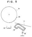
- Fig. 5 is a diagrammatic illustration of the part at which the transfer guide is used in a copying machine.
- a transfer guide 14 or fixing inlet guide comprised of a Ni-coated steel material is grounded through a voltage regulator (a varistor) to have a middle voltage so that toner stains and blank areas caused by poor transfer can be prevented.
- This method requires an increase in the number of component parts to bring about an increase in operational steps, and hence can not be mass-productive.
- the numeral 9 denotes a photosensitive member; 10, toner; 11, a transfer medium; and 13, a transfer charger.
- EP-A-0 230 633 a friction roll for working elongate members such as webs or strands, manufactured according to the preamble of Claim 1 is disclosed, which has a coating film consisting of a ceramic or metallic carbide only. Further, it is an essential feature that the surface of the ceramic or metallic carbide coatings are engraved by laser.
- An object of the present invention is to provide a method for manufacturing a sheet-like medium or paper delivery member having superior wear resistance and a good surface uniformity.
- Another object of the present invention is to provide a method for manufacturing a sheet-like medium or paper delivery member having superior wear resistance and a good surface uniformity, and also capable of being controlled on its conductivity.
- an electro-deposition coating film is formed by electrophoresis on a delivery member such as a roller member comprised of a metallic member or non-metallic member, using an electro-deposition coating composition comprising a resin feasible for electro-deposition and an inorganic powder contained therein.
- a delivery member that has a surface layer in which incorporated fine particles are uniformly dispersed, is less in change with time, and has a superior wear resistance and a good surface uniformity.
- the present invention can provide, in addition to the above characteristics, a delivery member having a superior controllability on its conductivity.
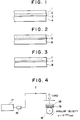
- Figs. 1, 2 and 3 are each a partial cross section to show an example of the constitution of the delivery member manufactured according to the present invention.
- the delivery member manufactured according to the present invention comprises a roller member comprised of a non-metallic member made of ABS resin or the like, on the surface of which a catalytically treated layer 3 and a metal coat layer 2 have been successively formed by a commonly known plating process applied to plastics, and on the base material of which, thus prepared, an electro-deposition coating film 1 is formed.
- Fig. 2 is a partial cross section to show another example of the constitution of the delivery member manufactured according to the present invention. It comprises a metallic member 6 made of aluminum or the like, on the surface of which an aluminum anodic oxidation coating layer 5 is formed, and on the base material of which, thus prepared, the electro-deposition coating film 1 is formed.
- Fig. 3 illustrates a delivery member comprising a metallic member 8 made of a steel material or the like, on the surface of which a chemical conversion coating layer 7 is formed, which is commonly known to be formed for the purpose of protection from corrosion, and on the base material of which, thus prepared, the electro-deposition coating film 1 is formed.
- any of metallic members made of aluminum, iron or the like and non-metallic members made of plastic or the like may be used.
- the treatments as shown in relation to Figs 1 to 3 or any other conventional treatments are applied as undercoating carried out before electro-deposition coating.
- the non-metallic members there are no particular limitations on the non-metallic members, and it is possible to use any plastic materials used in delivery members of office automation machinery, home electric apparatus, printers, etc., including, for example, ABS, CF/ABS, modified PPE, modified PPO, and GF/PC.
- the delivery member on which an electro-deposition coating film has been formed can be produced by subjecting the metallic member or nonmetallic member as described above to undercoating carried out before electro-deposition coating, and then carrying out the electro-deposition coating to form the electro-deposition coating film.
- a coating composition comprising a resin feasible for electro-deposition and an inorganic powder incorporated therein is used as the electro-deposition coating composition used in the electro-deposition coating.
- This electro-deposition coating composition can be used as an anionic one or a cationic one.
- the inorganic powder may preferably be at least one selected from ceramic powder, metal powder, and ceramic powder whose particle surfaces are coated with a metal (hereinafter "metallized ceramic powder").
- the metal powder and the metallized ceramic powder are effective as conductive inorganic powders.
- the ceramic powder and the metallized ceramic powder may preferably have a particle diameter of 0.1 ⁇ m to 3.0 ⁇ m.
- the metal powder may preferably have a particle diameter of 0.01 ⁇ m to 3.0 ⁇ m.
- the particle diameter of the inorganic powder is a value measured with a centrifugal sedimentation type particle size distribution measuring device.
- a device actually used as this measuring device is SACP-3 (manufactured by Shimadzu Corporation).
- low-temperature curable resins can be used, including, for example, acryl-melamine resins, acrylic resins, epoxy resins, urethane resins and alkyd resins.
- the ceramic powder a vast range of powders can be used without any particular limitations, preferably including SiC, SiO 2 , Si 3 N 4 , TaC, ZrO, Al 2 O 3 and NbC.
- the ceramic powder should have an average particle diameter usually in the range of from 0.1 ⁇ m to 3.0 ⁇ m, and preferably from 0.3 ⁇ m to 1.5 ⁇ m.
- An average particle diameter less than 0.1 ⁇ m and that more than 3.0 ⁇ m are not preferable since the former can not give the necessary surface roughness to the delivery member and the latter makes the surface roughness so large that the performance of paper pass may be lowered.
- the metal powder incorporated into the resin feasible for electro-deposition. It includes, for example, Ag, Co, Cu, Fe, Mn, Ni, Pd, Sn and Te.
- the metal powder should have an average particle diameter usually in the range of from 0.01 to 3.0 ⁇ m, and preferably from 0.1 to 1.0 ⁇ m. An average particle diameter less than 0.01 ⁇ m and that more than 3.0 ⁇ m are not preferable since the former causes secondary agglomeration when the powder is dispersed in the electro-deposition coating composition and the latter may result in a lowering of the uniform dispersibility of powder to the electro-deposition coating film.
- the metal powder may preferably be those produced by, for example, heat plasma evaporation, pulverizing, etc.
- the metallized ceramic powder may include a ceramic powder whose particle surfaces are coated with a metal such as Ag, Ni or Cu, and a nickel-coated ceramic powder whose particle surfaces are further plated with Au. From the viewpoint of cost, it is suitable for the metal coating on the ceramic powder particle surfaces to be carried out by electroless plating using nickel or copper.
- the ceramic powder should have an average particle diameter usually in the range of from 0.1 ⁇ m to 3.0 ⁇ m, and preferably from 0.3 ⁇ m to 1.5 ⁇ m.
- An average particle diameter less than 0.1 ⁇ m and that more than 3.0 ⁇ m are not preferable since the former results in an increase in cost for metal coating on ceramic powder and the latter brings about a lowering of uniform dispersibility in the electro-deposition coating film.
- the metal coating on the particle surfaces of the ceramic powder should be applied in a thickness usually ranging from 0.05 ⁇ m to 0.9 ⁇ m, and preferably from 0.1 ⁇ m to 0.5 ⁇ m.
- the inorganic powder may be contained in the electro-deposition coating composition in an amount ranging from 5 parts by weight to 50 parts by weight (5 parts by weight to 40 parts by weight in the case of the metal powder), and preferably from 5 parts by weight to 20 parts by weight, based on 100 parts by weight of the resin feasible for electro-deposition. Its addition within this range can give an electro-deposition coating film having a wear resistance uniformly good throughout the coating film.
- An amount less than 5 parts by weight and an amount more than 50 parts by weight (40 parts by weight in the case of the metal powder) are not preferable since the former may result in an insufficient surface roughness and the latter may result in a lowering of adhesion of the coating film to the base material.
- the conductivity of the electro-deposition coating film can be controlled to have any desired value, by appropriately controlling its content with respect to the resin feasible for electro-deposition.
- the inorganic powder it is effective to use a mixture of the metal powder and the metallized ceramic powder.
- they may preferably be mixed in such a proportion that the metallized ceramic powder is in the range of from 30 parts by weight to 300 parts by weight based on 100 parts by weight of the metal powder.
- the deposition of the inorganic powder can be confirmed using an X-ray microanalyzer.
- the content thereof can be measured by thermogravimetric analysis.
- the inorganic powder can be dispersed in the electro-deposition coating composition by carrying out dispersion for about 24 hours to about 35 hours using a ball mill, and thereafter diluting the dispersion with desalted water to have a concentration of 10 parts by weight to 15 parts by weight as solid contents in the same manner as in electro-deposition coating commonly used.
- the electro-deposition coating composition can be thus prepared.
- the electro-deposition coating can be of an anionic or cationic type.
- the electro-deposition should be carried out under conditions of a bath temperature ranging from 20°C to 25°C, a pH of 8 to 9, an applied voltage of 50 V to 200 V, a current density of 0.5 A/dm 2 to 3 A/dm 2 and a treatment time of 3 minutes to 5 minutes, where the article to be coated is set as the anode in the anionic electro-deposition coating, and as the cathode in the cationic electro-deposition coating. Subsequently, the coating formed is washed with water, followed by dewatering, and then cured in an oven of 100°C to 140°C for 20 minutes to 180 minutes. Thus the formation of the electro-deposition coating film is completed.
- the inorganic powder may be deposited in an amount of 5 % by weight to 50 % by weight, and preferably 20 % by weight to 40 % by weight.
- the electro-deposition coating film should have a coating thickness of not less than 5 ⁇ m, and preferably of 7 to 15 ⁇ m.
- the coating controlled in the thickness not less than 5 ⁇ m can give an electro-deposition coating film having a wear resistance uniformly good throughout the coating film.
- the above inorganic powder is dispersed in the resin and co-deposited in the electro-deposition coating film by the action of electrophoresis, so that coating film properties equal or superior to those of high-temperature cured films can be obtained since the curing reaction can perfectly proceed in spite of the low-temperature curing (100°C).
- the inorganic powders to be deposited in electro-deposition coating films were each dispersed in an amount of 6 to 11 parts by weight (in the case of the metal powder, 7 to 17 parts by weight) based on 100 parts by weight of acrylic resin.
- Anionic electro-deposition coating compositions were thus prepared. Electro-deposition coating was carried out to give a coating thickness of 10 ⁇ m on each roller member. Here, the electro-deposition was carried out at bath temperatures of 20 to 25°C and the curing was carried out for 60 minutes in an oven at a curing temperature of 100°C.
- Fig. 4 is a diagrammatic illustration of a surface properties testing device used to evaluate the wear resistance of roller members in the durability tests. Using this test device, coefficients of static friction at the roller members were measured before and after the durability tests to evaluate the wear resistance.
- roller members The durability tests on the roller members were each carried out using the same kind of two roller members, which were fitted to a copying machine, where running to pass 150,000 sheets of copying plain paper was carried out.
- the base roller member is comprised of a steel material, an aluminum material or an ABS resin material.
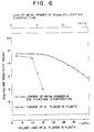
- Figs. 6 to 8 also show the results obtained when the volume resistivities were measured on conductive plastics formed by mixing aluminum flakes (size: 1.0 mm x 1.4 mm, 25 to 30 ⁇ m thick) into a plastic such as ABS, CF/ABS, modified PPE, modified PPO or GF/PC.
- a plastic such as ABS, CF/ABS, modified PPE, modified PPO or GF/PC.
- the volume resistivities of the kneaded products of aluminum with plastics were measured by the method described in "KOGYO ZAIRYO (Industrial Materials)", Nikkan Kogyo Shinbun Sha, Vol. 30, No. 10, p.54.
- the deposition coating is carried out by electrophoresis, no localized dispersion of additive fillers occurs, which may occur in the case of kneading, so that it is possible to obtain a coating film that is uniform over the whole surface of the delivery member.
- the electro-deposition coating composition used in the case of Fig. 6 is comprised of 13 % by weight of acrylic resin to which a nickel powder with an average particle diameter of 0.3 ⁇ m has been added.
- the electro-deposition coating composition used in the case of Fig. 7 is comprised of 12 % by weight of acrylic resin to which a ceramic powder with an average particle diameter of 1 ⁇ m whose particle surfaces are coated with nickel in a thickness of 0.1 ⁇ m has been added.
- the delivery member manufactured according to the present invention in the transfer guide, which is a delivery member in the copying machine shown in Fig. 5, since it is possible to obtain the same effect as in the case when the resistivity of the member is controlled using a voltage regulator.
- the deposition of the conductive inorganic powder by electro-deposition coating according to the manufacturing method of the present invention brings about enlarged contact areas of the powder and an increase in density thereof, and hence makes it possible to obtain a coating film that is uniform over the whole surface in both a macroscopic view and a microscopic view.
- the present invention can solve the problems involved in delivery members required to have a particularly highly precise surface uniformity and at the same time required to have wear resistance and conductivity.
- the present invention greatly contributes not only to improvement in characteristics but also to cost reduction.
- Fig. 9 schematically illustrates the constitution of a commonly available transfer electrophotographic apparatus in which a drum photosensitive member is used.
- the numeral 21 denotes a drum photosensitive member serving as an image supporting member, which is rotated around a shaft 21a at a given peripheral speed in the direction shown by an arrow.
- the photosensitive member 21 is uniformly charged on its periphery, with positive or negative given potential by the operation of a charging means 22, and then photoimagewise exposed to light L (slit exposure, laser beam scanning exposure, etc.) at an exposure zone 23 by the operation of an imagewise exposure means (not shown).
- electrostatic latent images corresponding to the exposure images are successively formed on the periphery of the photosensitive member.
- the electrostatic latent images thus formed are subsequently developed by toner by the operation of a developing means 24.
- the resulting toner-developed images are then successively transferred by the operation of a transfer means 25, to the surface of a transfer medium P fed from a paper feed section (not shown) to the part between the photosensitive member 21 and the transfer means 25 in the manner synchronized with the rotation of the photosensitive member 21.
- the transfer medium P on which the images have been transferred is separated from the surface of the photosensitive member and led through an image-fixing means 28, where the images are fixed and then delivered to the outside as a transcript (a copy).
- the surface of the photosensitive member 21 after the transfer of images is brought to removal of the toner remaining after the transfer, using a cleaning means 26.
- the photosensitive member is cleaned on its surface, further subjected to charge elimination by a pre-exposure means 27, and then repeatedly used for the formation of images.
- the transfer medium P such as transfer paper or transfer film is delivered by means of delivery guides 31, 32, 33, 34, 35 and 36, a pair of resist delivery rollers 29 and a delivery belt 30.
- the delivery member manufactured according to the present invention can be effectively applied to such delivery guides, delivery rollers and delivery belt.
- the charging means 22 for giving uniform charge on the photosensitive member 21 include corona chargers, which are commonly put into wide use. As the transfer means 25, corona transfer units are also commonly put into wide use.
- the electrophotographic apparatus may posess a single device unit constituted of plural constituents such as the above photosensitive member, developing means and cleaning means so that the unit can be freely removed from the body of the apparatus.
- the photosensitive member 21 and at least one of the charging means, developing means and cleaning means may be joined into a single device unit so that the unit can be freely mounted or detached using a guide means such as a rail (s) provided in the body of the apparatus.
- the above device unit may be constituted of the charging means and/or the developing means.
- the exposure of the photosensitive member is carried out with the optical image exposing light L by directing the light reflected from, or transmitted through an original, scanning a laser beam, or driving an LED array or a liquid crystal shutter array according to signals obtained by reading an original with a sensor and converting the information into signals.
- the optical image exposing light L serves as exposing light used for the printing of received data.
- Fig. 10 illustrates an example thereof in the form of a block diagram.
- a controller 41 controls an image reading part 40 and a printer 49.
- the whole of the controller 41 is controlled by CPU 47.
- Image data outputted from the image reading part is sent to the other facsimile station through a transmitting circuit 43.
- Data received from the other station is sent to a printer 49 through a receiving circuit 42.
- Given image data are stored in an image memory 46.
- a printer controller 48 controls the printer 49.
- the numeral 44 denotes a telephone.
- An image received from a circuit 45 (image information from a remote terminal connected through the circuit) is demodulated in the receiving circuit 42, and then successively stored in an image memory 46 after the image information is decoded by the CPU 47. Then, when images for at least one page have been stored in the memory 46, the image recording for that page is carried out.
- the CPU 47 reads out the image information for one page from the memory 46 and sends the coded image information for one page to the printer controller 48.
- the printer controller 48 having received the image information for one page from the CPU 47, controls the printer 49 so that the image information for one page is recorded.
- the CPU 47 receives image information for next page in the course of the recording by the printer 49.
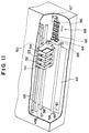
- Fig. 11 illustrates an ink-jet recording apparatus in which the delivery member manufactured according to the present invention is used.
- the numeral 56 denotes a scanning rail that extends in the main scanning direction of a carriage 50 and slidably supports the carriage 50; and 55, a belt that transmit a driving force for reciprocating the carriage 50.
- the numerals 59, 60 and numerals 57, 58 are pairs of rollers that constitute a mechanism for delivering a recording medium, which are disposed in front and in the rear, respectively, of the recording position at which ink is ejected from a recording head assembly, and between and through which the recording medium is held and delivered.
- the delivery member manufactured according to the present invention can be effectively applied to such rollers.
- the carriage 50 is fitted with a plurality of cartridges 51, 52, 53 and 54.
- Each cartridge is integrally constituted of an ink container and an ink-ejecting recording head assembly.
- the recording head assembly faces the recording medium being delivered in the direction of an arrow 61.
- the cartridges 51, 52, 53 and 54 eject inks of, for example, cyan, magenta, yellow and black colors, respectively.
- the numeral 64 denotes a blade serving as a wiping member; and 65, a blade cleaner formed of, for example, an absorber, used for complete cleaning of the blade 64.
- the blade 64 is retained by a blade elevating mechanism that is driven in accordance with the movement of the carriage 50.
- the blade 64 can be set in the position where it projects (upward movement) so as to perform cleaning by wiping the face that forms eject ion openings of the recording head assembly, or set in the position where it recedes (downward movement) so as not to interfere with that position.
- its mechanism is so designed that the blade 64 performs the wipe-cleaning when the carriage 50 moves from the right side to the left side, viewed in the drawing. If any part of the face that forms ejection openings of the head assembly remains not wiped by the blade 64, an auxiliary blade 63 may be provided at the position where it can be wiped.
- the numeral 67 denotes a pump assembly associated with a cap assembly 66, which is used to produce a negative pressure utilized when the cap assembly 66 is brought into contact with the face of ejection openings to carry out suction and so forth.
- ABS resin was formed into a roller member of 30 mm in outer diameter and 230 mm in length to give an article to be coated.
- This ABS resin roller member was treated with an etchant of a CrO 3 -H 2 SO 4 -H 2 O system for 1 minute. Thereafter, the resulting member was treated at room temperature for 2 minutes using as a sensitizer solution a solution comprised of 30 g/lit. of stannous chloride and 20 ml/lit. of hydrochloric acid, followed by catalytic treatment with palladium. Thereafter, nickel was applied by electroless plating in a thickness of 0.5 ⁇ m, followed by treatment with a solution of 0.01 g/lit. of chromic anhydride for 1 minute to give a test member.
- an acryl-melamine resin (trade name: Honey Bright C-IL; produced by Honey Chemical Co.) 10 to 15 parts by weight of fine aluminum oxide powder with an average particle diameter of 1 ⁇ m was dispersed for 30 hours using a ball mill, for each increase by 5 parts by weight, and then the dispersion was diluted with desalted water to 15 % by weight as a concentration of solid contents to make up a coating composition.
- electro-deposition was carried out for 3 minutes at applied voltages increasing at intervals of 50 V within the range of from 50 V to 150 V, under conditions of a bath temperature of 25°C and pH 8 to 9, setting the article to be coated as the anode and a 0.5t stainless steel plate as the opposing electrode.
- the electro-deposition coating film formed thereon had a coating thicknesses of 10 to 12 ⁇ m and the inorganic powder was contained in the coating film in a deposition quantity of 20 to 25 % by weight.
- the wear resistance of the electro-deposition coating film thus formed was tested to obtain a good result that the coefficient of static friction of the roller was 1.5 to 1.6 even after a durability test to pass 150,000 sheets of copying plain paper. In the meantime, the coefficient of static friction before the durability test was 2.0.
- a free-cutting leaded steel SLSUM was worked into a roller member of 30 mm in outer diameter and 230 mm in length to give an article to be coated.
- This roller member was degreased at 60°C for 5 minutes using a commonly known alkali type degreaser.
- an iron-phosphate chemical conversion coating was formed in a thickness of 3 ⁇ m, followed by thorough washing with pure water and then dewatering and drying to give a test member.
- an acryl-melamine resin (trade name: Honey Bright C-IL; produced by Honey Chemical Co.) 10 to 15 parts by weight of fine aluminum oxide powder with an average particle diameter of 1 ⁇ m was dispersed for 30 hours using a ball mill, for each increase by 5 parts by weight, and then the dispersion was diluted with desalted water to 15 % by weight as a concentration of solid contents to make up a coating composition.
- electro-deposit ion was carried out for 3 minutes at applied voltages increasing at intervals of 50 V within the range of from 50 V to 150 V, under conditions of a bath temperature of 25°C and pH 8 to 9, setting the article to be coated as the anode and a 0.5t stainless steel plate as the opposing electrode.
- the electro-deposition coating film formed thereon had a coating thicknesses of 8 to 12 ⁇ m and the inorganic powder was contained in the coating film in a deposition quantity of 18 to 25 % by weight.
- the wear resistance of the electro-deposition coating film thus formed was tested to obtain a good result that the coefficient of static friction of the roller was 1.5 to 1.7 even after a durability test to pass 150,000 sheets of copying plain paper. In the meantime, the coefficient of static friction before the durability test was 1.9 to 2.0.
- An aluminum 53S was worked into a roller member of 30 mm in outer diameter and 230 mm in length to give an article to be coated.
- an anodic oxidation coating of 3 ⁇ m thickness was formed by anodizing to give a test member.
- an acryl-melamine resin (trade name: Honey Bright C-IL; produced by Honey Chemical Co.) 10 to 15 parts by weight of fine aluminum oxide powder with an average particle diameter of 1 ⁇ m was dispersed for 30 hours using a ball mill, for each increase by 5 parts by weight, and then the dispersion was diluted with desalted water to 15 % by weight as a concentration of solid contents to make up a coating composition.
- electro-deposition was carried out for 3 minutes at applied voltages increasing at intervals of 50 V within the range of from 50 V to 150 V, under conditions of a bath temperature of 25°C and pH 8 to 9, setting the article to be coated as the anode and a 0.5t stainless steel plate as the opposing electrode.
- the electro-deposition coating film formed thereon had a coating thicknesses of 8 to 12 ⁇ m and the inorganic powder was contained in the coating film in a deposition quantity of 16 to 25 % by weight.
- the wear resistance of the electro-deposition coating film thus formed was tested to obtain a good result that the coefficient of static friction of the roller was 1.5 to 1.6 even after a durability test to pass 150,000 sheets of copying plain paper. In the meantime, the coefficient of static friction before the durability test was 1.8 to 2.0.
- a paper delivery member was produced in the same manner as in Example 1-1 except that 15 parts by weight of cobalt (Co) powder with an average particle diameter of 0.3 ⁇ m was used as the inorganic powder, the dispersion was carried out for 30 minutes using a ball mill, and the electro-deposition coating was carried out at applied voltages ranging from 100 V to 150 V.
- Co cobalt
- the wear resistance of the electro-deposition coating film thus formed was tested to obtain a good result that the coefficient of static friction of the roller was 1.4 to 1.7 even after a durability test to pass 150,000 sheets of copying plain paper. In the meantime, the coefficient of static friction before the durability test was 2.0 to 2.1.
- electro-deposition coating was applied by the same method as in Example 2-1.
- the electro-deposition coating film was formed using an electro-deposition coating composition prepared by dispersing in 100 parts by weight of an acryl-melamine resin (trade name: Honey Bright C-IL; produced by Honey Chemical Co.) 11 to 13 parts by weight of fine nickel powder with an average particle diameter of 0.3 ⁇ m.
- the electro-deposition coating film thus formed had a coating thicknesses of 10 to 12 ⁇ m and the inorganic powder was contained in the coating film in a deposition quantity of 30 to 35 % by weight.
- the transfer guide having the electro-deposition coating film thus formed had a volume resistivity of 10 7 to 10 9 ⁇ cm, and no paper contamination due to adhesion of toner occurred even when the transfer guide was set in a copying machine and copying was repeated 10,000 times in an environment of a low humidity (25 % RH). No faulty operation such as blank areas in images also occurred even in an environment of a high humidity (85 % RH). Thus the transfer guide showed a good performance as a paper delivery member.
- the coefficient of static friction which is a value of physical properties that shows changes in wear resistance
- a value as good as 1.4 to 1.5 was obtained after the durability test.
- the coefficient of static friction before the durability test was 1.8 to 1.9.
- test member was prepared in the same manner as in Example 1-2.
- electro-deposition was carried out for 3 minutes at applied voltages ranging from 100 V to 150 V, under conditions of a bath temperature of 25°C and pH 8 to 9, setting the article to be coated as the anode and a 0.5t stainless plate sheet as the opposing electrode.
- the electro-deposition coating film formed thereon had a coating thicknesses of 11 to 13 ⁇ m and the inorganic powder was contained in the coating film in a deposition quantity of 26 to 32 % by weight.
- the wear resistance of the electro-deposition coating film thus formed was tested to obtain a good result that the coefficient of static friction of the roller was 1.7 to 1.8 even after a durability test to pass 150,000 sheets of copying plain paper. In the meantime, the coefficient of static friction before the durability test was 2.0.
- test member was prepared in the same manner as in Example 1-3.
- electro-deposition was carried out for 3 minutes at applied voltages ranging from 100 V to 150 V, under conditions of a bath temperature of 25°C and pH 8 to 9, setting the article to be coated as the anode and a 0.5t stainless steel plate as the opposing electrode.
- the electro-deposition coating film formed thereon had a coating thicknesses of 10 to 12 ⁇ m and the inorganic powder was contained in the coating film in a deposition quantity of 31 to 36 % by weight.
- the wear resistance of the electro-deposition coating film thus formed was tested to obtain a good result that the coefficient of static friction of the roller was 1.5 to 1.6 even after a durability test to pass 150,000 sheets of copying plain paper. In the meantime, the coefficient of static friction before the durability test was 1.8 to 1.9.
- a pretreatment before electro-deposition coating was carried out in the same manner as in Example 2-3.
- an acryl-melamine resin (trade name: Honey Bright C-IL; produced by Honey Chemical Co.) 11 to 13 parts by weight of fine nickel powder with an average particle diameter of 0.3 ⁇ m was dispersed for 30 hours using a ball mill, and then the dispersion was diluted with desalted water to 15 % by weight of solid contents to make up a coating composition.
- electro-deposition was carried out for 3 minutes at applied voltages ranging from 100 V to 150 V, under conditions of a bath temperature of 25°C and pH 8 to 9, setting the article to be coated as the anode and a 0.5t stainless steel plate as the opposing electrode.
- the coated articles were washed with water and then heated in an oven of 120°C ⁇ 1°C for 50 minutes to effect curing. Electro-deposition coated members were thus completed.
- the electro-deposition coating films formed thereon each had a coating thicknesses of 11 to 13 ⁇ m and the inorganic powder was contained in each coating film in a deposition quantity of 30 to 35 % by weight.
- the transfer guide and the fixing inlet guide each having the electro-deposition coating film thus formed had a volume resistivity of 10 7 to 10 9 ⁇ cm, and no paper contamination due to adhesion of toner occurred even when they were set in a copying machine and copying was repeated 10,000 times in an environment of a low humidity (25 % RH). No faulty operation such as blank areas in images also occurred even in an environment of a high humidity (85 % RH). Thus these members showed good performance as paper delivery members.
- the coefficient of static friction which is a value of physical properties that shows changes in wear resistance
- a value as good as 1.4 to 1.6 was obtained after the durability test.
- the coefficient of static friction before the durability test was 1.8 to 1.9.
- test member was prepared in the same manner as in Example 1-1.
- an acryl-melamine resin (trade name: Honey Bright C-IL; produced by Honey Chemical Co.)
- 10 parts by weight of aluminum oxide with an average particle diameter of 1 ⁇ m whose particle surfaces were coated with nickel by electroless plating in a thickness of 0.1 ⁇ m was dispersed for 30 hours using a ball mill, and then the dispersion was diluted with desalted water to 15 % by weight of solid contents to make up a coating composition.
- electro-deposition was carried out for 3 minutes at applied voltages ranging from 100 V to 150 V, under conditions of a bath temperature of 25°C and pH 8 to 9, setting the article to be coated as the anode and a 0.5t stainless steel plate as the opposing electrode.
- the electro-deposition coating film formed thereon had a coating thicknesses of 10 to 12 ⁇ m and the inorganic powder was contained in the coating film in a deposition quantity of 20 to 25 % by weight.
- the wear resistance of the electro-deposition coating film thus formed was tested to obtain a good result that the coefficient of static friction of the roller was 1.5 to 1.6 even after a durability test to pass 150,000 sheets of copying plain paper. In the meantime, the coefficient of static friction before the durability test was 1.9 to 2.0.
- electro-deposition coating film was formed using an electro-deposition coating composition prepared by dispersing in 100 parts by weight of an acryl-melamine resin (trade name: Honey Bright C-IL; produced by Honey Chemical Co.) 8 parts by weight of Al 2 O 3 with an average particle diameter of 1 ⁇ m whose particle surfaces were coated with nickel by electroless plating in a thickness of 0.1 ⁇ m.
- the electro-deposition was carried out at applied voltages of 100 V to 150 V and, in respect of other conditions, under the same conditions as in Example 3-1.
- the electro-deposition coating film thus formed had a coating thicknesses of 10 to 12 ⁇ m and the inorganic powder was contained in the coating film in a deposition quantity of 20 to 25 % by weight.
- the transfer guide having the electro-deposition coating film thus formed had a volume resistivity of 10 7 to 10 9 ⁇ cm, and no paper contamination due to adhesion of toner occurred even when the transfer guide was set in a copying machine and copying was repeated 10,000 times in an environment of a low humidity (25 % RH). No faulty operation such as blank areas in images also occurred even in an environment of a high humidity (85 % RH). Thus the transfer guide showed a good performance as a paper delivery member.
- the coefficient of static friction which is a value of physical properties that shows changes in wear resistance
- a value as good as 1.4 to 1.6 was obtained after the durability test.
- the coefficient of static friction before the durability test was 1.8 to 1.9.
- a free-cutting leaded steel SLSUM was worked into a roller member of 30 mm in outer diameter and 230 mm in length to give an article to be coated.
- This roller member was degreased at 60°C for 5 minutes using a commonly known alkali type degreaser.
- an iron-phosphate chemical conversion coating was formed in a thickness of 3 ⁇ m, followed by thorough washing with pure water and then dewatering and drying to give a test member.
- an acryl-melamine resin (trade name: Honey Bright C-IL; produced by Honey Chemical Co.) 9 parts by weight of aluminum oxide powder with an average particle diameter of 1 ⁇ m whose particle surfaces were coated with nickel by electroless plating in a thickness of 0.1 ⁇ m was dispersed for 30 hours using a ball mill, and then the dispersion was diluted with desalted water to 15 % by weight of solid contents to make up a coating composition.
- electro-deposition was carried out for 3 minutes at applied voltages ranging from 100 V to 150 V, under conditions of a bath temperature of 25°C and pH 8 to 9, setting the article to be coated as the anode and a 0.5t stainless steel plate as the opposing electrode.
- the electro-deposition coating film formed thereon had a coating thicknesses of 11 to 13 ⁇ m and the inorganic powder was contained in the coating film in a deposition quantity of 20 to 25 % by weight.
- the wear resistance of the electro-deposition coating film thus formed was tested to obtain a good result that the coefficient of static friction of the roller was 1.5 to 1.6 even after a durability test to pass 150,000 sheets of copying plain paper. In the meantime, the coefficient of static friction before the durability test was 2.0.
- An aluminum 53S was worked into a roller member of 30 mm in outer diameter and 230 mm in length to give an article to be coated. On this aluminum roller member, an anodized aluminum coating was formed by anodizing to give a test member.
- an acryl-melamine resin (trade name: Honey Bright C-IL; produced by Honey Chemical Co.) 15 parts by weight of aluminum oxide powder with an average particle diameter of 0.7 ⁇ m whose particle surfaces were coated with nickel by electroless plating in a thickness of 0.1 ⁇ m was dispersed for 30 hours using a ball mill, and then the dispersion was diluted with desalted water to 15 % by weight of solid contents to make up a coating composition.
- electro-deposition was carried out for 3 minutes at applied voltages ranging from 100 V to 150 V, under conditions of a bath temperature of 25°C and pH 8 to 9, setting the article to be coated as the anode and a 0.5t stainless steel plate as the opposing electrode.
- the electro-deposition coating film formed thereon had a coating thicknesses of 10 to 12 ⁇ m and the inorganic powder was contained in the coating film in a deposition quantity of 25 to 30 % by weight.
- the wear resistance of the electro-deposition coating film thus formed was tested to obtain a good result that the coefficient of static friction of the roller was 1.5 to 1.6 even after a durability test to pass 150,000 sheets of copying plain paper. In the meantime, the coefficient of static friction before the durability test was to 2.0.
- a pretreatment before electro-deposition coating was carried out in the same manner as in Example 3-3.
- an acryl-melamine resin (trade name: Honey Bright C-IL; produced by Honey Chemical Co.) 8 parts by weight of aluminum oxide powder with an average particle diameter of 1 ⁇ m whose particle surfaces were coated with nickel by electroless plating in a thickness of 0.1 ⁇ m was dispersed for 30 hours using a ball mill, and then the dispersion was diluted with desalted water to 15 % by weight of solid contents to make up a coating composition.
- electro-deposition was carried out for 3 minutes at applied voltages ranging from 100 V to 150 V, under conditions of a bath temperature of 25°C and pH 8 to 9, setting the article to be coated as the anode and a 0.5t stainless steel plate as the opposing electrode.
- the coated articles were washed with water and then heated in an oven of 120°C ⁇ 1°C for 50 minutes to effect curing. Electro-deposition coated members were thus completed.
- the electro-deposition coating films formed thereon each had a coating thicknesses of 11 to 13 ⁇ m and the inorganic powder was contained in each coating film in a deposition quantity of 25 to 30 % by weight.
- the transfer guide and the fixing inlet guide each having the electro-deposition coating film thus formed had a volume resistivity of 10 7 to 10 9 ⁇ cm, and no paper contamination due to adhesion of toner occurred even when they were set in a copying machine and copying was repeated 10,000 times in an environment of a low humidity (25 % RH). No faulty operation such as blank areas in images also occurred even in an environment of a high humidity (85 % RH). Thus these members showed good performance as paper delivery members.
- the coefficient of static friction which is a value of physical properties that shows changes in wear resistance
- a value as good as 1.4 to 1.5 was obtained after the durability test.
- the coefficient of static friction before the durability test was 1.9.
- test member was prepared in the same manner as in Example 1-1.
- an acryl-melamine resin (trade name: Honey Bright C-IL; produced by Honey Chemical Co.)
- 8 parts by weight of cobalt (Co) powder with an average particle diameter of 0.3 ⁇ m were dispersed for 30 hours using a ball mill, and then the dispersion was diluted with desalted water to 15 % by weight of solid contents to make up a coating composition.
- electro-deposition was carried out for 3 minutes at applied voltages ranging from 100 V to 150 V, under conditions of a bath temperature of 25°C and pH 8 to 9, setting the article to be coated as the anode and a 0.5t stainless steel plate as the opposing electrode.
- the electro-deposition coating film formed thereon had a coating thicknesses of 10 to 12 ⁇ m and the inorganic powder was contained in the coating film in a deposition quantity of 35 to 40 % by weight.
- the wear resistance of the electro-deposition coating film thus formed was tested to obtain a good result that the coefficient of static friction of the roller was 1.4 to 1.6 even after a durability test to pads 150,000 sheets of copying plain paper. In the meantime, the coefficient of static friction before the durability test was 1.8 to 1.9.
- electro-deposition coating film was formed using an electro-deposition coating composition prepared by dispersing in 100 parts by weight of an acryl-melamine resin (trade name: Honey Bright C-IL; produced-by Honey Chemical Co.) 4 parts by weight of Al 2 O 3 with an average particle diameter of 1 ⁇ m whose particle surfaces were coated with nickel by electroless plating in a thickness of 0.1 ⁇ m and 5 parts by weight of fine tungsten (W) powder with an average particle diameter of 0.3 ⁇ m.
- the electro-deposition was carried out at applied voltages of 100 V to 150 V and, in respect of other conditions, under the same conditions as in Example 4-1.
- the electro-deposition coating film thus formed had a coating thicknesses of 10 to 12 ⁇ m and the inorganic powder was contained in the coating film in a deposition quantity of 23 to 28 % by weight.
- the transfer guide having the electro-deposition coating film thus formed had a volume resistivity of 10 7 to 10 9 ⁇ cm, and no paper contamination due to adhesion of toner occurred even when the transfer guide was set in a copying machine and copying was repeated 10,000 times in an environment of a low humidity (25 % RH). No faulty operation such as blank areas in images also occurred even in an environment of a high humidity (85 % RH). Thus the transfer guide showed a good performance as a paper delivery member.
- the coefficient of static friction which is a value of physical properties that shows changes in wear resistance
- a value as good as 1.4 to 1.6 was obtained after the durability test.
- the coefficient of static friction before the durability test was 1.8 to 1.9.
- a free-cutting leaded steel SLSUM was worked into a roller member of 30 mm in outer diameter and 230 mm in length to give an article to be coated.
- This roller member was degreased at 60°C for 5 minutes using a commonly known alkali type degreaser.
- an iron-phosphate chemical conversion coating was formed in a thickness of 3 ⁇ m, followed by thorough washing with pure water and then dewatering and drying to give a test member.
- an acryl-melamine resin (trade name: Honey Bright C-IL; produced by Honey Chemical Co.)
- 9 parts by weight of aluminum oxide powder with an average particle diameter of 1 ⁇ m whose particle surfaces were coated with nickel by electroless plating in a thickness of 0.1 ⁇ m and 4 parts by weight of titanium (Ti) powder with an average particle diameter of 0.3 ⁇ m were dispersed for 30 hours using a ball mill, and then the dispersion was diluted with desalted water to 15 % by weight of solid contents to make up a coating composition.
- electro-deposition was carried out for 3 minutes at applied voltages ranging from 100 V to 150 V, under conditions of a bath temperature of 25°C and pH 8 to 9, setting the article to be coated as the anode and a 0.5t stainless steel plate as the opposing electrode.
- the electro-deposition coating film formed thereon had a coating thicknesses of 12 to 14 ⁇ m and the inorganic powder was contained in the coating film in a deposition quantity of 24 to 28 % by weight.
- the wear resistance of the electro-deposition coating film thus formed was tested to obtain a good result that the coefficient of static friction of the roller was 1.5 to 1.6 even after a durability test to pass 150,000 sheets of copying plain paper. In the meantime, the coefficient of static friction before the durability test was 1.9 to 2.0.
- An aluminum 53S was worked into a roller member of 30 mm in outer diameter and 230 mm in length to give an article to be coated. On this aluminum roller member, an anodic oxidation coating was formed by anodizing to give a test member.
- an acryl-melamine resin (trade name: Honey Bright C-IL; produced by Honey Chemical Co.)
- 4 parts by weight of aluminum oxide powder with an average particle diameter of 1 ⁇ m whose particle surfaces were coated with copper by electroless plating in a thickness of 0.1 ⁇ m and 12 parts by weight of cobalt (Co) powder with an average particle diameter of 0.3 ⁇ m were dispersed for 30 hours using a ball mill, and then the dispersion was diluted with desalted water to 15 % by weight of solid contents to make up a coating composition.
- electro-deposition was carried out for 3 minutes at applied voltages ranging from 100 V to 150 V, under conditions of a bath temperature of 25°C and pH 8 to 9, setting the article to be coated as the anode and a 0.5t stainless steel plate as the opposing electrode.
- the electro-deposition coating film formed thereon had a coating thicknesses of 10 to 12 ⁇ m and the inorganic powder was contained in the coating film in a deposition quantity of 33 to 38 % by weight.
- the wear resistance of the electro-deposition coating film thus formed was tested to obtain a good result that the coefficient of static friction of the roller was 1.5 to 1.6 even after a durability test to pass 150,000 sheets of copying plain paper. In the meantime, the coefficient of static friction before the durability test was to 1.9 to 2.0.
- a pretreatment before electro-deposition coating was carried out in the same manner as in Example 4-3.
- an acryl-melamine resin (trade name: Honey Bright C-IL; produced by Honey Chemical Co.)
- 3 parts by weight of aluminum oxide powder with an average particle diameter of 1 ⁇ m whose particle surfaces were coated with nickel by electroless plating in a thickness of 0.1 ⁇ m and 7 parts by weight of silver powder with an average particle diameter of 0.3 ⁇ m were dispersed for 30 hours using a ball mill, and then the dispersion was diluted with desalted water to 15 % by weight as a concentration of solid contents to make up a coating composition.
- electro-deposition was carried out for 3 minutes at applied voltages ranging from 100 V to 150 V, under conditions of a bath temperature of 25°C and pH 8 to 9, setting the article to be coated as the anode and a 0.5t stainless steel plate as the opposing electrode.
- the coated articles were washed with water and then heated in an oven of 120°C ⁇ 1°C for 50 minutes to effect curing. Electro-deposition coated members were thus completed.
- the electro-deposition coating films formed thereon each had a coating thicknesses of 11 to 13 ⁇ m and the inorganic powder was contained in each coating film in a deposition quantity of 26 to 32 % by weight.
- the transfer guide and the fixing inlet guide each having the electro-deposition coating film thus formed had a volume resistivity of 10 7 to 10 9 ⁇ cm, and no paper contamination due to adhesion of toner occurred even when they were set in a copying machine and copying was repeated 10,000 times in an environment of a low humidity (25 % RH). No faulty operation such as blank areas in images also occurred even in an environment of a high humidity (85 % RH). Thus these members showed good performance as paper delivery members.
- the coefficient of static friction which is a value of physical properties that shows changes in wear resistance
- a value as good as 1.4 to 1.5 was obtained after the durability test.
- the coefficient of static friction before the durability test was 1.8 to 1.9.
Landscapes
- Chemical & Material Sciences (AREA)
- Engineering & Computer Science (AREA)
- Chemical Kinetics & Catalysis (AREA)
- Electrochemistry (AREA)
- Materials Engineering (AREA)
- Metallurgy (AREA)
- Organic Chemistry (AREA)
- Physics & Mathematics (AREA)
- General Physics & Mathematics (AREA)
- Rolls And Other Rotary Bodies (AREA)
- Electrostatic Charge, Transfer And Separation In Electrography (AREA)
- Delivering By Means Of Belts And Rollers (AREA)
- Other Surface Treatments For Metallic Materials (AREA)
- Application Of Or Painting With Fluid Materials (AREA)
Description
- The present invention relates to a method of manufacturing a sheet-like medium or paper delivery member. The thus manufactured sheet-like or paper delivery member is suitably used in paper delivery members of office automation machinery, home electric apparatus, printers, etc., or at their parts through which film sheets, plastic sheets and other sheet-like mediums or paper are delivered. The present invention also relates to a method of manufacturing an electrophotographic apparatus, a facsimile machine or an ink-jek recording apparatus, each of these methods including the step of the mentioned manufacturing of said sheet-like medium or paper delivery member.
- Delivery members hitherto used, such as roller members used for paper transport in office automation machinery, home electric apparatus, printers, etc. are exemplified by those comprising a steel material whose surface is plated, thereafter covered with rubber and then coated with Teflon (trademark), those comprising a steel material whose surface is plated and then coated with aluminum oxide by electrostatic spraying or subjected to composite plating to form a coating containing SiC or diamond dust, those comprising a steel material whose surface is roughed by sandblasting or using a laser, those in which plating is applied to their surface thus roughened, and those comprising a steel material spray-coated thereon with a coating composition in which metal fine particles or fillers have been mixed.
- These delivery members, when used, are further grounded through a voltage regulator so that the resistivity at the part through which paper passes (hereinafter "paper-pass part") can be controlled to be of a middle value.
- The conventional delivery members, however, have the following disadvantages.
- In the first place, in the case of the delivery member comprising a roller member spray-coated with a coating composition in which metal fine particles or fillers have been mixed, there is a limit in the simultaneous coating of a plurality of members by means of a set of coating robot when a high-grade surface uniformity is required as in the delivery members, even if an automation line is adopted in the manufacturing process. Moreover, the state of surfaces of coatings becomes non-uniform because of diffusion of coating compositions to cause a big problem in both the mass productivity and the surface properties.
- The delivery member comprising a roll member comprised of a steel material whose surface is plated, thereafter covered with rubber and then coated with Teflon, has the problem that changes with time as a result of repeated use bring about a deformation of rubber to lower outside diameter precision and cause faulty paper feed and output. This not only lowers its commercial value but also requires a prolonged process in its manufacture, lowers operating efficiency, and results in a high production cost. Thus, there is a great problem in its mass productivity.
- As for the delivery member comprising a roller member whose surface, e.g., stainless steel surface has been sandblasted to increase a coefficient of surface friction, the member has the problem that its material is so high in hardness that it is difficult to enhance work precision, also resulting in an increase in both the material cost and the manufacturing cost.
- Similarly, the delivery member comprising a steel material whose surface is roughed by sandblasting tends to rust on its surface add hence requires a treatment for rust prevention, e.g., plating, carried out in a subsequent step for the purpose of protection from corrosion. In such an instance, the plating is carried out on the sandblasted surface, having a low outside diameter precision, so that the outside diameter precision is further lowered and also the number of manufacturing steps increases. Thus this member can not be mass-produced.
- In the case of the delivery member comprising a steel material whose surface is roughed using a laser to increase a coefficient of friction, only one member can be manufactured at one time when it is a roller or the like, and moreover it takes a long time for that treatment. Thus this member also can not be mass-produced.
- The delivery member comprising a steel material whose surface is plated and then coated with aluminum oxide by electrostatic spraying to increase the wear resistance or hardness of its surface can not be stable in the adhesion and uniformity of aluminum oxide and the final outside diameter precision. There is also a limit in the manufacture of uniform-quality goods in large quantities and at a low cost.
- Besides, the delivery member comprising a metallic member whose surface is subjected to electroless plating and then, in a subsequent step, subjected to composite plating to form a coating containing SiC or diamond dust has the problem that, for example, impurities tend to be included in a composite plating bath to make the bath unstable and hence the bath can not be durable to repeated use. Moreover, there are a disadvantage of high cost in plating solutions and a problem of a poor uniform dispersibility, bringing about a big problem in manufacturing cost.
- In many instances, it is an important factor to impart conductivity to the delivery member. For example, conductive paper delivery members are used in copying machines or the like at their many paper-pass parts, and resistivity is controlled at the paper-pass parts.
- Namely, in the case when a paper delivery member at a paper-pass part that comes into contact with paper has insulation properties, the paper delivery member produces triboelectricity due to friction between paper and the member in an environment of low humidity, so that toner may adhere to the paper delivery member to produce a stain on the paper. In the case when a paper delivery member at a paper-pass part has a low resistivity, the paper itself comes to serve as a low-resistive element in an environment of high humidity because of its moisture absorption, so that the charges produced may leak through a transfer guide to cause blank areas of images.
- Fig. 5 is a diagrammatic illustration of the part at which the transfer guide is used in a copying machine. In conventional copying machines, as shown in the drawing, a
transfer guide 14 or fixing inlet guide comprised of a Ni-coated steel material is grounded through a voltage regulator (a varistor) to have a middle voltage so that toner stains and blank areas caused by poor transfer can be prevented. This method, however, requires an increase in the number of component parts to bring about an increase in operational steps, and hence can not be mass-productive. In the drawing, thenumeral 9 denotes a photosensitive member; 10, toner; 11, a transfer medium; and 13, a transfer charger. - In EP-A-0 230 633 a friction roll for working elongate members such as webs or strands, manufactured according to the preamble of
Claim 1 is disclosed, which has a coating film consisting of a ceramic or metallic carbide only. Further, it is an essential feature that the surface of the ceramic or metallic carbide coatings are engraved by laser. - The present invention was made in order to solve these problems involved in the prior art. An object of the present invention is to provide a method for manufacturing a sheet-like medium or paper delivery member having superior wear resistance and a good surface uniformity.
- Another object of the present invention is to provide a method for manufacturing a sheet-like medium or paper delivery member having superior wear resistance and a good surface uniformity, and also capable of being controlled on its conductivity.
- The present invention is achieved by the features of
claim 1. - According to the present invention, an electro-deposition coating film is formed by electrophoresis on a delivery member such as a roller member comprised of a metallic member or non-metallic member, using an electro-deposition coating composition comprising a resin feasible for electro-deposition and an inorganic powder contained therein. This makes it possible to provide a delivery member that has a surface layer in which incorporated fine particles are uniformly dispersed, is less in change with time, and has a superior wear resistance and a good surface uniformity. In an instance where the in organic powder is conductive, the present invention can provide, in addition to the above characteristics, a delivery member having a superior controllability on its conductivity.
-
- Figs. 1, 2 and 3 are each a partial cross section to show an example of the constitution of the delivery member manufactured according to the present invention
- Fig. 4 is a diagrammatic illustration of a surface properties testing device used in the measurement of the wear resistance of delivery members.
- Fig. 5 is a diagrammatic illustration of the part at which a transfer guide is used in a copying machine.
- Figs. 6, 7 and 8 are each a graph to show values measured on the volume resistivities of a flat plate provided with an electro-deposition coating film and a plastic loaded with aluminum flakes.
- Fig. 9 is a schematic illustration of the constitution of a transfer electrophotographic apparatus in which the delivery member manufactured according to the present invention is used.
- Fig. 10 is a block diagram of a facsimile system in which the above electrophotographic apparatus is used.
- Fig. 11 is a schematic illustration of an ink-jet recording apparatus in which the delivery member manufactured according to the present invention is used.
-
- Figs. 1, 2 and 3 are each a partial cross section to show an example of the constitution of the delivery member manufactured according to the present invention. In Fig. 1, the delivery member manufactured according to the present invention comprises a roller member comprised of a non-metallic member made of ABS resin or the like, on the surface of which a catalytically treated
layer 3 and ametal coat layer 2 have been successively formed by a commonly known plating process applied to plastics, and on the base material of which, thus prepared, an electro-deposition coating film 1 is formed. - Fig. 2 is a partial cross section to show another example of the constitution of the delivery member manufactured according to the present invention. It comprises a metallic member 6 made of aluminum or the like, on the surface of which an aluminum anodic
oxidation coating layer 5 is formed, and on the base material of which, thus prepared, the electro-deposition coating film 1 is formed. - Fig. 3 illustrates a delivery member comprising a metallic member 8 made of a steel material or the like, on the surface of which a chemical conversion coating layer 7 is formed, which is commonly known to be formed for the purpose of protection from corrosion, and on the base material of which, thus prepared, the electro-
deposition coating film 1 is formed. - As a substrate provided in the method according to the present invention, any of metallic members made of aluminum, iron or the like and non-metallic members made of plastic or the like may be used. Depending on the properties thereof, the treatments as shown in relation to Figs 1 to 3 or any other conventional treatments are applied as undercoating carried out before electro-deposition coating. There are no particular limitations on the non-metallic members, and it is possible to use any plastic materials used in delivery members of office automation machinery, home electric apparatus, printers, etc., including, for example, ABS, CF/ABS, modified PPE, modified PPO, and GF/PC.
- The delivery member on which an electro-deposition coating film has been formed can be produced by subjecting the metallic member or nonmetallic member as described above to undercoating carried out before electro-deposition coating, and then carrying out the electro-deposition coating to form the electro-deposition coating film.
- A coating composition comprising a resin feasible for electro-deposition and an inorganic powder incorporated therein is used as the electro-deposition coating composition used in the electro-deposition coating. This electro-deposition coating composition can be used as an anionic one or a cationic one.
- The inorganic powder may preferably be at least one selected from ceramic powder, metal powder, and ceramic powder whose particle surfaces are coated with a metal (hereinafter "metallized ceramic powder"). The metal powder and the metallized ceramic powder are effective as conductive inorganic powders.
- The ceramic powder and the metallized ceramic powder may preferably have a particle diameter of 0.1 µm to 3.0 µm. The metal powder may preferably have a particle diameter of 0.01 µm to 3.0 µm.
- The particle diameter of the inorganic powder is a value measured with a centrifugal sedimentation type particle size distribution measuring device. A device actually used as this measuring device is SACP-3 (manufactured by Shimadzu Corporation).
- As the resin feasible for electro-deposition, commonly known low-temperature curable resins can be used, including, for example, acryl-melamine resins, acrylic resins, epoxy resins, urethane resins and alkyd resins.
- As the ceramic powder, a vast range of powders can be used without any particular limitations, preferably including SiC, SiO2, Si3N4, TaC, ZrO, Al2O3 and NbC.
- The ceramic powder should have an average particle diameter usually in the range of from 0.1 µm to 3.0 µm, and preferably from 0.3 µm to 1.5 µm. An average particle diameter less than 0.1 µm and that more than 3.0 µm are not preferable since the former can not give the necessary surface roughness to the delivery member and the latter makes the surface roughness so large that the performance of paper pass may be lowered.
- There are no particular limitations on the metal powder incorporated into the resin feasible for electro-deposition. It includes, for example, Ag, Co, Cu, Fe, Mn, Ni, Pd, Sn and Te. As to the particle diameter, the metal powder should have an average particle diameter usually in the range of from 0.01 to 3.0 µm, and preferably from 0.1 to 1.0 µm. An average particle diameter less than 0.01 µm and that more than 3.0 µm are not preferable since the former causes secondary agglomeration when the powder is dispersed in the electro-deposition coating composition and the latter may result in a lowering of the uniform dispersibility of powder to the electro-deposition coating film.
- The metal powder may preferably be those produced by, for example, heat plasma evaporation, pulverizing, etc.
- The metallized ceramic powder may include a ceramic powder whose particle surfaces are coated with a metal such as Ag, Ni or Cu, and a nickel-coated ceramic powder whose particle surfaces are further plated with Au. From the viewpoint of cost, it is suitable for the metal coating on the ceramic powder particle surfaces to be carried out by electroless plating using nickel or copper.
- The ceramic powder should have an average particle diameter usually in the range of from 0.1 µm to 3.0 µm, and preferably from 0.3 µm to 1.5 µm. An average particle diameter less than 0.1 µm and that more than 3.0 µm are not preferable since the former results in an increase in cost for metal coating on ceramic powder and the latter brings about a lowering of uniform dispersibility in the electro-deposition coating film. The metal coating on the particle surfaces of the ceramic powder should be applied in a thickness usually ranging from 0.05 µm to 0.9 µm, and preferably from 0.1 µm to 0.5 µm.
- The inorganic powder may be contained in the electro-deposition coating composition in an amount ranging from 5 parts by weight to 50 parts by weight (5 parts by weight to 40 parts by weight in the case of the metal powder), and preferably from 5 parts by weight to 20 parts by weight, based on 100 parts by weight of the resin feasible for electro-deposition. Its addition within this range can give an electro-deposition coating film having a wear resistance uniformly good throughout the coating film. An amount less than 5 parts by weight and an amount more than 50 parts by weight (40 parts by weight in the case of the metal powder) are not preferable since the former may result in an insufficient surface roughness and the latter may result in a lowering of adhesion of the coating film to the base material.
- When the conductive inorganic powder is used, the conductivity of the electro-deposition coating film can be controlled to have any desired value, by appropriately controlling its content with respect to the resin feasible for electro-deposition.
- As the inorganic powder, it is effective to use a mixture of the metal powder and the metallized ceramic powder. In such an instance, they may preferably be mixed in such a proportion that the metallized ceramic powder is in the range of from 30 parts by weight to 300 parts by weight based on 100 parts by weight of the metal powder.
- The deposition of the inorganic powder can be confirmed using an X-ray microanalyzer. The content thereof can be measured by thermogravimetric analysis.
- The inorganic powder can be dispersed in the electro-deposition coating composition by carrying out dispersion for about 24 hours to about 35 hours using a ball mill, and thereafter diluting the dispersion with desalted water to have a concentration of 10 parts by weight to 15 parts by weight as solid contents in the same manner as in electro-deposition coating commonly used. The electro-deposition coating composition can be thus prepared. The electro-deposition coating can be of an anionic or cationic type.
The electro-deposition should be carried out under conditions of a bath temperature ranging from 20°C to 25°C, a pH of 8 to 9, an applied voltage of 50 V to 200 V, a current density of 0.5 A/dm2 to 3 A/dm2 and a treatment time of 3 minutes to 5 minutes, where the article to be coated is set as the anode in the anionic electro-deposition coating, and as the cathode in the cationic electro-deposition coating.
Subsequently, the coating formed is washed with water, followed by dewatering, and then cured in an oven of 100°C to 140°C for 20 minutes to 180 minutes. Thus the formation of the electro-deposition coating film is completed. In the coating film thus formed, the inorganic powder may be deposited in an amount of 5 % by weight to 50 % by weight, and preferably 20 % by weight to 40 % by weight. - The electro-deposition coating film should have a coating thickness of not less than 5 µm, and preferably of 7 to 15 µm. The coating controlled in the thickness not less than 5 µm can give an electro-deposition coating film having a wear resistance uniformly good throughout the coating film.
- In the present invention, the above inorganic powder is dispersed in the resin and co-deposited in the electro-deposition coating film by the action of electrophoresis, so that coating film properties equal or superior to those of high-temperature cured films can be obtained since the curing reaction can perfectly proceed in spite of the low-temperature curing (100°C).
- Durability tests were carried out on various roller members to obtain the results shown in Tables 1 to 3. The roller members tested were uniformed to have the same outer diameter of 30 mm.
- In regard to Tables 1 to 3, the inorganic powders to be deposited in electro-deposition coating films were each dispersed in an amount of 6 to 11 parts by weight (in the case of the metal powder, 7 to 17 parts by weight) based on 100 parts by weight of acrylic resin. Anionic electro-deposition coating compositions were thus prepared. Electro-deposition coating was carried out to give a coating thickness of 10 µm on each roller member. Here, the electro-deposition was carried out at bath temperatures of 20 to 25°C and the curing was carried out for 60 minutes in an oven at a curing temperature of 100°C.
- Fig. 4 is a diagrammatic illustration of a surface properties testing device used to evaluate the wear resistance of roller members in the durability tests. Using this test device, coefficients of static friction at the roller members were measured before and after the durability tests to evaluate the wear resistance.
- The durability tests on the roller members were each carried out using the same kind of two roller members, which were fitted to a copying machine, where running to pass 150,000 sheets of copying plain paper was carried out.
- The coefficients of static friction of roller members before and after the durability tests were measured in the following way: In the device shown in Fig. 4, copy paper 19 (A4 size) was secured to the back of a copy
paper securing plate 18 with flat surface, which was then brought into contact with aroller member 1 of 30 mm in outer diameter and 230 mm in length, where a maximum load of 1 to 2 kg was applied from the top and the roller member was rotated in the direction of an arrow at an angular velocity ω of 1.5 rad/sec to measure a coefficient of static friction. - When the roller member is made of rubber, judgement was made only on whether any faulty paper pass occurred during the running test.
- Results obtained are shown in Tables 1 to 3.
Inorganic powder to be deposited in electro-deposition coating film Inorganic powder average particle diameter (µ) Coefficient of static friction before running Coefficient of static friction after running Delivery performance after running SiC 1.0 2.0 1.7 Good Si3N4 1.0 2.1 1.6 Good TaC 1.0 2.0 1.5 Good Al2O3 1.0 2.0 1.5 Good Al2O3(Ni)* 1.0 1.9 1.5 Good Al2O3(Cu)** 1.0 2.0 1.5 Good SiO2 1.0 1.9 1.5 Good SiO2(Ni)*** 1.0 2.0 1.6 Good Cr2O3 1.0 1.9 1.5 Good Stainless steel member sandblasted 2.0 1.5 Good Steel material sandblasted and then Ni-coated by electroless plating 1.9 0.7 Poor Steel sheet plated, covered with rubber and then coated with Teflon Not measured Not measured Faulty delivery upon 100,000 sheets running Inorganic powder to be deposited in electro-deposition coating film Inorganic powder average particle diameter (µ) Coefficient of static friction before running Coefficient of static friction after running Delivery performance after running Te 0.3 1.9 1.6 Good Co 0.3 2.0 1.6 Good Ni 0.3 1.8 1.5 Good Mo 0.3 1.8 1.5 Good Ti 0.3 1.9 1.5 Good W 0.3 2.0 1.5 Good Diamond 0.3 2.0 1.5 Good Zr 0.3 2.0 1.4 Good Inorganic powder to be deposited in electro-deposition coating film Inorganic powder average particle diameter (µ) Coefficient of static friction before running Coefficient of static friction after running Delivery performance after running Al2O3(Ni)*+W 1.0+0.3 2.0 1.6 Good Al2O3(Ni)*+Co 1.0+0.3 2.1 1.6 Good Al2O3(Ni)*+Ti 1.0+0.3 2.0 1.5 Good Al2O3(Ni)*+Mo 1.0+0.3 2.0 1.5 Good Al2O3(Ni)*+Te 1.0+0.3 2.0 1.5 Good Al2O3(Ni)*+Ni 1.0+0.3 2.0 1.5 Good Al2O3(Cu)**+W 1.0+0.3 1.9 1.4 Good Al2O3(Cu)**+Co 1.0+0.3 1.9 1.4 Good - In Tables 1 to 3;
- (1) the data of durability tests are based on 150,000 sheet running tests;
- (2) the asterisk * indicates that particle surfaces of A2O3 were coated with nickel by electroless plating in a coating thickness of 0.1 µm;
- (3) the asterisks ** indicates that particle surfaces of A2O3 were coated with copper by electroless plating in a coating thickness of 0.1 µm;
- (4) the asterisks *** indicates that particle surfaces of SiO2 were coated with nickel by electroless plating in a coating thickness of 0.1 µm; and
- (5) the faulty paper delivery occurred on those with a static friction coefficient of 1.2 or less, measured with the surface properties testing device.
-
- From the results shown in Table 1 to 3, the wear resistance of the paper delivery roller members with the deposits of inorganic powders was found to be equal or superior to that of the roller member comprising a sandblasted stainless steel member.
- No changes were seen wherever the base roller member is comprised of a steel material, an aluminum material or an ABS resin material.
- Figs. 6 to 8 are graphs to show the results obtained when the volume resistivities were measured using a contact type insulation resistance meter, on electro-deposition coating films of 20 µm in coating thickness, formed on one side of aluminum 53S test pieces (size: 5 cm x 5 cm, t = 1.0 mm) by the use of electro-deposition ("ED." in the drawings) coating compositions comprising an acrylic resin and varied conductive inorganic powders. The resistivities were measured by bringing a four-point probe into contact with the electro-deposition coating film at a measurement area of 1 cm2.
- Figs. 6 to 8 also show the results obtained when the volume resistivities were measured on conductive plastics formed by mixing aluminum flakes (size: 1.0 mm x 1.4 mm, 25 to 30 µm thick) into a plastic such as ABS, CF/ABS, modified PPE, modified PPO or GF/PC. Here, the volume resistivities of the kneaded products of aluminum with plastics were measured by the method described in "KOGYO ZAIRYO (Industrial Materials)", Nikkan Kogyo Shinbun Sha, Vol. 30, No. 10, p.54.
- In the case of the plastics into which aluminum flakes are kneaded, an abrupt decrease in volume resistivity is seen within the range of from 0 to 1010 Ω·cm with an increase in the load of aluminum flakes. On the other hand, the electro-deposition costing films formed by mixing conductive inorganic powders into electro-deposition coating compositions show volume resistivities with mild changes, and hence it is possible to produce in a good precision, delivery members having any desired specific resistivities.
- Moreover, since the deposition coating is carried out by electrophoresis, no localized dispersion of additive fillers occurs, which may occur in the case of kneading, so that it is possible to obtain a coating film that is uniform over the whole surface of the delivery member.
- The electro-deposition coating composition used in the case of Fig. 6 is comprised of 13 % by weight of acrylic resin to which a nickel powder with an average particle diameter of 0.3 µm has been added. The electro-deposition coating composition used in the case of Fig. 7 is comprised of 12 % by weight of acrylic resin to which a ceramic powder with an average particle diameter of 1 µm whose particle surfaces are coated with nickel in a thickness of 0.1 µm has been added. The electro-deposition coating composition used in the case of Fig. 8 is comprised of 12 % by weight of acrylic resin to which a mixture of a nickel powder with an average particle diameter of 0.3 µm and a ceramic fine powder (Al2O3) with an average particle diameter of 1 µm whose particle surfaces are coated with nickel in a thickness of 0.1 µm (mixing proportion: 7:1) has been added.
- It is preferred to use the delivery member manufactured according to the present invention in the transfer guide, which is a delivery member in the copying machine shown in Fig. 5, since it is possible to obtain the same effect as in the case when the resistivity of the member is controlled using a voltage regulator.
- As described above, the deposition of the conductive inorganic powder by electro-deposition coating according to the manufacturing method of the present invention, brings about enlarged contact areas of the powder and an increase in density thereof, and hence makes it possible to obtain a coating film that is uniform over the whole surface in both a macroscopic view and a microscopic view. Thus, the present invention can solve the problems involved in delivery members required to have a particularly highly precise surface uniformity and at the same time required to have wear resistance and conductivity. Moreover, the present invention greatly contributes not only to improvement in characteristics but also to cost reduction.
- In addition, compared with an instance in which a delivery member is formed by molding using a kneaded product prepared by mixing a conductive filler into rubber and plastic, use of the delivery member manufactured according to the present invention makes it possible to obtain a better wear resistance and any desired conductivity even though any conductive filler is used in an extremely small quantity. Thus the present invention also have a superior economical effect.
- Use examples of the delivery member manufactured according to the present invention will be described below with reference to Figs. 9, 10 and 11.
- Fig. 9 schematically illustrates the constitution of a commonly available transfer electrophotographic apparatus in which a drum photosensitive member is used.
- In Fig. 9, the numeral 21 denotes a drum photosensitive member serving as an image supporting member, which is rotated around a
shaft 21a at a given peripheral speed in the direction shown by an arrow. In the course of rotation, thephotosensitive member 21 is uniformly charged on its periphery, with positive or negative given potential by the operation of a charging means 22, and then photoimagewise exposed to light L (slit exposure, laser beam scanning exposure, etc.) at anexposure zone 23 by the operation of an imagewise exposure means (not shown). As a result, electrostatic latent images corresponding to the exposure images are successively formed on the periphery of the photosensitive member. - The electrostatic latent images thus formed are subsequently developed by toner by the operation of a developing
means 24. The resulting toner-developed images are then successively transferred by the operation of a transfer means 25, to the surface of a transfer medium P fed from a paper feed section (not shown) to the part between thephotosensitive member 21 and the transfer means 25 in the manner synchronized with the rotation of thephotosensitive member 21. - The transfer medium P on which the images have been transferred is separated from the surface of the photosensitive member and led through an image-fixing means 28, where the images are fixed and then delivered to the outside as a transcript (a copy).
- The surface of the
photosensitive member 21 after the transfer of images is brought to removal of the toner remaining after the transfer, using a cleaning means 26. Thus the photosensitive member is cleaned on its surface, further subjected to charge elimination by a pre-exposure means 27, and then repeatedly used for the formation of images. - The transfer medium P such as transfer paper or transfer film is delivered by means of delivery guides 31, 32, 33, 34, 35 and 36, a pair of resist
delivery rollers 29 and adelivery belt 30. The delivery member manufactured according to the present invention can be effectively applied to such delivery guides, delivery rollers and delivery belt. - The charging means 22 for giving uniform charge on the
photosensitive member 21 include corona chargers, which are commonly put into wide use. As the transfer means 25, corona transfer units are also commonly put into wide use. - The electrophotographic apparatus may posess a single device unit constituted of plural constituents such as the above photosensitive member, developing means and cleaning means so that the unit can be freely removed from the body of the apparatus. For example, the
photosensitive member 21 and at least one of the charging means, developing means and cleaning means may be joined into a single device unit so that the unit can be freely mounted or detached using a guide means such as a rail (s) provided in the body of the apparatus. Here, the above device unit may be constituted of the charging means and/or the developing means. - In the case when the electrophotographic apparatus is used as a copying machine or a printer, the exposure of the photosensitive member is carried out with the optical image exposing light L by directing the light reflected from, or transmitted through an original, scanning a laser beam, or driving an LED array or a liquid crystal shutter array according to signals obtained by reading an original with a sensor and converting the information into signals.
- When used as a printer of a facsimile machine, the optical image exposing light L serves as exposing light used for the printing of received data. Fig. 10 illustrates an example thereof in the form of a block diagram.
- As shown in Fig. 10, a
controller 41 controls animage reading part 40 and aprinter 49. The whole of thecontroller 41 is controlled byCPU 47. Image data outputted from the image reading part is sent to the other facsimile station through a transmittingcircuit 43. Data received from the other station is sent to aprinter 49 through a receivingcircuit 42. Given image data are stored in animage memory 46. Aprinter controller 48 controls theprinter 49. The numeral 44 denotes a telephone. - An image received from a circuit 45 (image information from a remote terminal connected through the circuit) is demodulated in the receiving
circuit 42, and then successively stored in animage memory 46 after the image information is decoded by theCPU 47. Then, when images for at least one page have been stored in thememory 46, the image recording for that page is carried out. TheCPU 47 reads out the image information for one page from thememory 46 and sends the coded image information for one page to theprinter controller 48. Theprinter controller 48, having received the image information for one page from theCPU 47, controls theprinter 49 so that the image information for one page is recorded. - The
CPU 47 receives image information for next page in the course of the recording by theprinter 49. - Images are received and recorded in the above way.
- Fig. 11 illustrates an ink-jet recording apparatus in which the delivery member manufactured according to the present invention is used.
- In Fig. 11, the numeral 56 denotes a scanning rail that extends in the main scanning direction of a
carriage 50 and slidably supports thecarriage 50; and 55, a belt that transmit a driving force for reciprocating thecarriage 50. Thenumerals 59, 60 andnumerals - The
carriage 50 is fitted with a plurality ofcartridges arrow 61. Thecartridges - In a
restoration assembly 68, the numeral 64 denotes a blade serving as a wiping member; and 65, a blade cleaner formed of, for example, an absorber, used for complete cleaning of theblade 64. In the present example, theblade 64 is retained by a blade elevating mechanism that is driven in accordance with the movement of thecarriage 50. Thus theblade 64 can be set in the position where it projects (upward movement) so as to perform cleaning by wiping the face that forms eject ion openings of the recording head assembly, or set in the position where it recedes (downward movement) so as not to interfere with that position. In the present example, its mechanism is so designed that theblade 64 performs the wipe-cleaning when thecarriage 50 moves from the right side to the left side, viewed in the drawing. If any part of the face that forms ejection openings of the head assembly remains not wiped by theblade 64, anauxiliary blade 63 may be provided at the position where it can be wiped. - In the restoration assembly, the numeral 67 denotes a pump assembly associated with a
cap assembly 66, which is used to produce a negative pressure utilized when thecap assembly 66 is brought into contact with the face of ejection openings to carry out suction and so forth. - An ABS resin was formed into a roller member of 30 mm in outer diameter and 230 mm in length to give an article to be coated. This ABS resin roller member was treated with an etchant of a CrO3-H2SO4-H2O system for 1 minute. Thereafter, the resulting member was treated at room temperature for 2 minutes using as a sensitizer solution a solution comprised of 30 g/lit. of stannous chloride and 20 ml/lit. of hydrochloric acid, followed by catalytic treatment with palladium. Thereafter, nickel was applied by electroless plating in a thickness of 0.5 µm, followed by treatment with a solution of 0.01 g/lit. of chromic anhydride for 1 minute to give a test member.
- In 100 parts by weight of an acryl-melamine resin (trade name: Honey Bright C-IL; produced by Honey Chemical Co.), 10 to 15 parts by weight of fine aluminum oxide powder with an average particle diameter of 1 µm was dispersed for 30 hours using a ball mill, for each increase by 5 parts by weight, and then the dispersion was diluted with desalted water to 15 % by weight as a concentration of solid contents to make up a coating composition.
- Using this coating composition, electro-deposition was carried out for 3 minutes at applied voltages increasing at intervals of 50 V within the range of from 50 V to 150 V, under conditions of a bath temperature of 25°C and pH 8 to 9, setting the article to be coated as the anode and a 0.5t stainless steel plate as the opposing electrode.
- After the electro-deposition, the coated article was washed with water and then heated in an oven of 97°C ± 1°C for 60 minutes to effect curing. An electro-deposition coated member was thus completed. The electro-deposition coating film formed thereon had a coating thicknesses of 10 to 12 µm and the inorganic powder was contained in the coating film in a deposition quantity of 20 to 25 % by weight.
- The wear resistance of the electro-deposition coating film thus formed was tested to obtain a good result that the coefficient of static friction of the roller was 1.5 to 1.6 even after a durability test to pass 150,000 sheets of copying plain paper. In the meantime, the coefficient of static friction before the durability test was 2.0.
- A free-cutting leaded steel SLSUM was worked into a roller member of 30 mm in outer diameter and 230 mm in length to give an article to be coated. This roller member was degreased at 60°C for 5 minutes using a commonly known alkali type degreaser. Next, after thorough washing with water, an iron-phosphate chemical conversion coating was formed in a thickness of 3 µm, followed by thorough washing with pure water and then dewatering and drying to give a test member.
- In 100 parts by weight of an acryl-melamine resin (trade name: Honey Bright C-IL; produced by Honey Chemical Co.), 10 to 15 parts by weight of fine aluminum oxide powder with an average particle diameter of 1 µm was dispersed for 30 hours using a ball mill, for each increase by 5 parts by weight, and then the dispersion was diluted with desalted water to 15 % by weight as a concentration of solid contents to make up a coating composition.
- Using this coating composition, electro-deposit ion was carried out for 3 minutes at applied voltages increasing at intervals of 50 V within the range of from 50 V to 150 V, under conditions of a bath temperature of 25°C and pH 8 to 9, setting the article to be coated as the anode and a 0.5t stainless steel plate as the opposing electrode.
- After the electro-deposition, the coated article was washed with water and then heated in an oven of 120°C ± 1°C for 50 minutes to effect curing. An electro-deposition coated member was thus completed. The electro-deposition coating film formed thereon had a coating thicknesses of 8 to 12 µm and the inorganic powder was contained in the coating film in a deposition quantity of 18 to 25 % by weight.
- The wear resistance of the electro-deposition coating film thus formed was tested to obtain a good result that the coefficient of static friction of the roller was 1.5 to 1.7 even after a durability test to pass 150,000 sheets of copying plain paper. In the meantime, the coefficient of static friction before the durability test was 1.9 to 2.0.
- An aluminum 53S was worked into a roller member of 30 mm in outer diameter and 230 mm in length to give an article to be coated. On this aluminum roller member, an anodic oxidation coating of 3 µm thickness was formed by anodizing to give a test member.
- In 100 parts by weight of an acryl-melamine resin (trade name: Honey Bright C-IL; produced by Honey Chemical Co.), 10 to 15 parts by weight of fine aluminum oxide powder with an average particle diameter of 1 µm was dispersed for 30 hours using a ball mill, for each increase by 5 parts by weight, and then the dispersion was diluted with desalted water to 15 % by weight as a concentration of solid contents to make up a coating composition.
- Using this coating composition, electro-deposition was carried out for 3 minutes at applied voltages increasing at intervals of 50 V within the range of from 50 V to 150 V, under conditions of a bath temperature of 25°C and pH 8 to 9, setting the article to be coated as the anode and a 0.5t stainless steel plate as the opposing electrode.
- After the electro-deposition, the coated article was washed with water and then heated in an oven of 120°C ± 1°C for 50 minutes to effect curing. An electro-deposition coated member was thus completed. The electro-deposition coating film formed thereon had a coating thicknesses of 8 to 12 µm and the inorganic powder was contained in the coating film in a deposition quantity of 16 to 25 % by weight.
- The wear resistance of the electro-deposition coating film thus formed was tested to obtain a good result that the coefficient of static friction of the roller was 1.5 to 1.6 even after a durability test to pass 150,000 sheets of copying plain paper. In the meantime, the coefficient of static friction before the durability test was 1.8 to 2.0.
- A paper delivery member was produced in the same manner as in Example 1-1 except that 15 parts by weight of cobalt (Co) powder with an average particle diameter of 0.3 µm was used as the inorganic powder, the dispersion was carried out for 30 minutes using a ball mill, and the electro-deposition coating was carried out at applied voltages ranging from 100 V to 150 V.
- The wear resistance of the electro-deposition coating film thus formed was tested to obtain a good result that the coefficient of static friction of the roller was 1.4 to 1.7 even after a durability test to pass 150,000 sheets of copying plain paper. In the meantime, the coefficient of static friction before the durability test was 2.0 to 2.1.
- On a transfer guide prepared by molding an ABS resin, electro-deposition coating was applied by the same method as in Example 2-1. Here, the electro-deposition coating film was formed using an electro-deposition coating composition prepared by dispersing in 100 parts by weight of an acryl-melamine resin (trade name: Honey Bright C-IL; produced by Honey Chemical Co.) 11 to 13 parts by weight of fine nickel powder with an average particle diameter of 0.3 µm. The electro-deposition coating film thus formed had a coating thicknesses of 10 to 12 µm and the inorganic powder was contained in the coating film in a deposition quantity of 30 to 35 % by weight.
- The transfer guide having the electro-deposition coating film thus formed had a volume resistivity of 107 to 109 Ω·cm, and no paper contamination due to adhesion of toner occurred even when the transfer guide was set in a copying machine and copying was repeated 10,000 times in an environment of a low humidity (25 % RH). No faulty operation such as blank areas in images also occurred even in an environment of a high humidity (85 % RH). Thus the transfer guide showed a good performance as a paper delivery member.
- This performance did not change throughout a durability test carried out by 150,000 sheet plain paper copying.
- As for the coefficient of static friction, which is a value of physical properties that shows changes in wear resistance, a value as good as 1.4 to 1.5 was obtained after the durability test. In the meantime, the coefficient of static friction before the durability test was 1.8 to 1.9.
- A test member was prepared in the same manner as in Example 1-2.
- In 100 parts by weight of an acryl-melamine resin (trade name: Honey Bright C-IL; produced by Honey Chemical Co.), 12 parts by weight of tungsten (W) powder with an average particle diameter of 0.3 µm was dispersed for 30 hours using a ball mill, and then the dispersion was diluted with desalted water to 15 % by weight as a concentration of solid contents to make up a coating composition.
- Using this coating composition, electro-deposition was carried out for 3 minutes at applied voltages ranging from 100 V to 150 V, under conditions of a bath temperature of 25°C and pH 8 to 9, setting the article to be coated as the anode and a 0.5t stainless plate sheet as the opposing electrode.
- After the electro-deposition, the coated article was washed with water and then heated in an oven of 120°C ± 1°C for 50 minutes to effect curing. An electro-deposition coated member was thus completed. The electro-deposition coating film formed thereon had a coating thicknesses of 11 to 13 µm and the inorganic powder was contained in the coating film in a deposition quantity of 26 to 32 % by weight.
- The wear resistance of the electro-deposition coating film thus formed was tested to obtain a good result that the coefficient of static friction of the roller was 1.7 to 1.8 even after a durability test to pass 150,000 sheets of copying plain paper. In the meantime, the coefficient of static friction before the durability test was 2.0.
- A test member was prepared in the same manner as in Example 1-3.
- In 100 parts by weight of an acryl-melamine resin (trade name: Honey Bright C-IL; produced by Honey Chemical Co.), 15 parts by weight of molybdenum (Mo) powder with an average particle diameter of 0.3 µm was dispersed for 30 hours using a ball mill, and then the dispersion was diluted with desalted water to 15 % by weight of solid contents to make up a coating composition.
- Using this coating composition, electro-deposition was carried out for 3 minutes at applied voltages ranging from 100 V to 150 V, under conditions of a bath temperature of 25°C and pH 8 to 9, setting the article to be coated as the anode and a 0.5t stainless steel plate as the opposing electrode.
- After the electro-deposition, the coated article was washed with water and then heated in an oven of 120°C ± 1°C for 50 minutes to effect curing. An electro-deposition coated member was thus completed. The electro-deposition coating film formed thereon had a coating thicknesses of 10 to 12 µm and the inorganic powder was contained in the coating film in a deposition quantity of 31 to 36 % by weight.
- The wear resistance of the electro-deposition coating film thus formed was tested to obtain a good result that the coefficient of static friction of the roller was 1.5 to 1.6 even after a durability test to pass 150,000 sheets of copying plain paper. In the meantime, the coefficient of static friction before the durability test was 1.8 to 1.9.
- An Spcc-D material (a steel sheet of t = 0.5 mm) was worked into a transfer guide and a fixing inlet guide, which were used as articles to be coated. A pretreatment before electro-deposition coating was carried out in the same manner as in Example 2-3.
- In 100 parts by weight of an acryl-melamine resin (trade name: Honey Bright C-IL; produced by Honey Chemical Co.), 11 to 13 parts by weight of fine nickel powder with an average particle diameter of 0.3 µm was dispersed for 30 hours using a ball mill, and then the dispersion was diluted with desalted water to 15 % by weight of solid contents to make up a coating composition.
- Using this coating composition, electro-deposition was carried out for 3 minutes at applied voltages ranging from 100 V to 150 V, under conditions of a bath temperature of 25°C and pH 8 to 9, setting the article to be coated as the anode and a 0.5t stainless steel plate as the opposing electrode.
- After the electro-deposition, the coated articles were washed with water and then heated in an oven of 120°C ± 1°C for 50 minutes to effect curing. Electro-deposition coated members were thus completed. The electro-deposition coating films formed thereon each had a coating thicknesses of 11 to 13 µm and the inorganic powder was contained in each coating film in a deposition quantity of 30 to 35 % by weight.
- The transfer guide and the fixing inlet guide each having the electro-deposition coating film thus formed had a volume resistivity of 107 to 109 Ω·cm, and no paper contamination due to adhesion of toner occurred even when they were set in a copying machine and copying was repeated 10,000 times in an environment of a low humidity (25 % RH). No faulty operation such as blank areas in images also occurred even in an environment of a high humidity (85 % RH). Thus these members showed good performance as paper delivery members.
- This performance did not change throughout a durability test carried out by 150,000 sheet plain paper copying.
- As for the coefficient of static friction, which is a value of physical properties that shows changes in wear resistance, a value as good as 1.4 to 1.6 was obtained after the durability test. In the meantime, the coefficient of static friction before the durability test was 1.8 to 1.9.
- A test member was prepared in the same manner as in Example 1-1.
- In 100 parts by weight of an acryl-melamine resin (trade name: Honey Bright C-IL; produced by Honey Chemical Co.), 10 parts by weight of aluminum oxide with an average particle diameter of 1 µm whose particle surfaces were coated with nickel by electroless plating in a thickness of 0.1 µm was dispersed for 30 hours using a ball mill, and then the dispersion was diluted with desalted water to 15 % by weight of solid contents to make up a coating composition.
- Using this coating composition, electro-deposition was carried out for 3 minutes at applied voltages ranging from 100 V to 150 V, under conditions of a bath temperature of 25°C and pH 8 to 9, setting the article to be coated as the anode and a 0.5t stainless steel plate as the opposing electrode.
- After the electro-deposition, the coated article was washed with water and then heated in an oven of 97°C ± 1°C for 60 minutes to effect curing. An electro-deposition coated member was thus completed. The electro-deposition coating film formed thereon had a coating thicknesses of 10 to 12 µm and the inorganic powder was contained in the coating film in a deposition quantity of 20 to 25 % by weight.
- The wear resistance of the electro-deposition coating film thus formed was tested to obtain a good result that the coefficient of static friction of the roller was 1.5 to 1.6 even after a durability test to pass 150,000 sheets of copying plain paper. In the meantime, the coefficient of static friction before the durability test was 1.9 to 2.0.
- On a transfer guide formed of an ABS resin, electro-deposition coating film was formed using an electro-deposition coating composition prepared by dispersing in 100 parts by weight of an acryl-melamine resin (trade name: Honey Bright C-IL; produced by Honey Chemical Co.) 8 parts by weight of Al2O3 with an average particle diameter of 1 µm whose particle surfaces were coated with nickel by electroless plating in a thickness of 0.1 µm. The electro-deposition was carried out at applied voltages of 100 V to 150 V and, in respect of other conditions, under the same conditions as in Example 3-1. The electro-deposition coating film thus formed had a coating thicknesses of 10 to 12 µm and the inorganic powder was contained in the coating film in a deposition quantity of 20 to 25 % by weight.
- The transfer guide having the electro-deposition coating film thus formed had a volume resistivity of 107 to 109 Ω·cm, and no paper contamination due to adhesion of toner occurred even when the transfer guide was set in a copying machine and copying was repeated 10,000 times in an environment of a low humidity (25 % RH). No faulty operation such as blank areas in images also occurred even in an environment of a high humidity (85 % RH). Thus the transfer guide showed a good performance as a paper delivery member.
- This performance did not change throughout a durability test carried out by 150,000 sheet plain paper copying.
- As for the coefficient of static friction, which is a value of physical properties that shows changes in wear resistance, a value as good as 1.4 to 1.6 was obtained after the durability test. In the meantime, the coefficient of static friction before the durability test was 1.8 to 1.9.
- A free-cutting leaded steel SLSUM was worked into a roller member of 30 mm in outer diameter and 230 mm in length to give an article to be coated. This roller member was degreased at 60°C for 5 minutes using a commonly known alkali type degreaser. Next, after thorough washing with water, an iron-phosphate chemical conversion coating was formed in a thickness of 3 µm, followed by thorough washing with pure water and then dewatering and drying to give a test member.
- In 100 parts by weight of an acryl-melamine resin (trade name: Honey Bright C-IL; produced by Honey Chemical Co.), 9 parts by weight of aluminum oxide powder with an average particle diameter of 1 µm whose particle surfaces were coated with nickel by electroless plating in a thickness of 0.1 µm was dispersed for 30 hours using a ball mill, and then the dispersion was diluted with desalted water to 15 % by weight of solid contents to make up a coating composition.
- Using this coating composition, electro-deposition was carried out for 3 minutes at applied voltages ranging from 100 V to 150 V, under conditions of a bath temperature of 25°C and pH 8 to 9, setting the article to be coated as the anode and a 0.5t stainless steel plate as the opposing electrode.
- After the electro-deposition, the coated article was washed with water and then heated in an oven of 110°C ± 1°C for 60 minutes to effect curing. An electro-deposition coated member was thus completed. The electro-deposition coating film formed thereon had a coating thicknesses of 11 to 13 µm and the inorganic powder was contained in the coating film in a deposition quantity of 20 to 25 % by weight.
- The wear resistance of the electro-deposition coating film thus formed was tested to obtain a good result that the coefficient of static friction of the roller was 1.5 to 1.6 even after a durability test to pass 150,000 sheets of copying plain paper. In the meantime, the coefficient of static friction before the durability test was 2.0.
- An aluminum 53S was worked into a roller member of 30 mm in outer diameter and 230 mm in length to give an article to be coated. On this aluminum roller member, an anodized aluminum coating was formed by anodizing to give a test member.
- In 100 parts by weight of an acryl-melamine resin (trade name: Honey Bright C-IL; produced by Honey Chemical Co.), 15 parts by weight of aluminum oxide powder with an average particle diameter of 0.7 µm whose particle surfaces were coated with nickel by electroless plating in a thickness of 0.1 µm was dispersed for 30 hours using a ball mill, and then the dispersion was diluted with desalted water to 15 % by weight of solid contents to make up a coating composition.
- Using this coating composition, electro-deposition was carried out for 3 minutes at applied voltages ranging from 100 V to 150 V, under conditions of a bath temperature of 25°C and pH 8 to 9, setting the article to be coated as the anode and a 0.5t stainless steel plate as the opposing electrode.
- After the electro-deposition, the coated article was washed with water and then heated in an oven of 120°C ± 1°C for 60 minutes to effect curing. An electro-deposition coated member was thus completed. The electro-deposition coating film formed thereon had a coating thicknesses of 10 to 12 µm and the inorganic powder was contained in the coating film in a deposition quantity of 25 to 30 % by weight.
- The wear resistance of the electro-deposition coating film thus formed was tested to obtain a good result that the coefficient of static friction of the roller was 1.5 to 1.6 even after a durability test to pass 150,000 sheets of copying plain paper. In the meantime, the coefficient of static friction before the durability test was to 2.0.
- An Spcc-D material (a steel sheet of t = 0.5 mm) was worked into a transfer guide and a fixing inlet guide, which were used as articles to be coated. A pretreatment before electro-deposition coating was carried out in the same manner as in Example 3-3.
- In 100 parts by weight of an acryl-melamine resin (trade name: Honey Bright C-IL; produced by Honey Chemical Co.), 8 parts by weight of aluminum oxide powder with an average particle diameter of 1 µm whose particle surfaces were coated with nickel by electroless plating in a thickness of 0.1 µm was dispersed for 30 hours using a ball mill, and then the dispersion was diluted with desalted water to 15 % by weight of solid contents to make up a coating composition.
- Using this coating composition, electro-deposition was carried out for 3 minutes at applied voltages ranging from 100 V to 150 V, under conditions of a bath temperature of 25°C and pH 8 to 9, setting the article to be coated as the anode and a 0.5t stainless steel plate as the opposing electrode.
- After the electro-deposition, the coated articles were washed with water and then heated in an oven of 120°C ± 1°C for 50 minutes to effect curing. Electro-deposition coated members were thus completed. The electro-deposition coating films formed thereon each had a coating thicknesses of 11 to 13 µm and the inorganic powder was contained in each coating film in a deposition quantity of 25 to 30 % by weight.
- The transfer guide and the fixing inlet guide each having the electro-deposition coating film thus formed had a volume resistivity of 107 to 109 Ω·cm, and no paper contamination due to adhesion of toner occurred even when they were set in a copying machine and copying was repeated 10,000 times in an environment of a low humidity (25 % RH). No faulty operation such as blank areas in images also occurred even in an environment of a high humidity (85 % RH). Thus these members showed good performance as paper delivery members.
- This performance did not change throughout a durability test carried out by 150,000 sheet plain paper copying.
- As for the coefficient of static friction, which is a value of physical properties that shows changes in wear resistance, a value as good as 1.4 to 1.5 was obtained after the durability test. In the meantime, the coefficient of static friction before the durability test was 1.9.
- A test member was prepared in the same manner as in Example 1-1.
- In 100 parts by weight of an acryl-melamine resin (trade name: Honey Bright C-IL; produced by Honey Chemical Co.), 8 parts by weight of aluminum oxide with an average particle diameter of 1 µm whose particle surfaces were coated with nickel by electroless plating in a thickness of 0.1 µm and 8 parts by weight of cobalt (Co) powder with an average particle diameter of 0.3 µm were dispersed for 30 hours using a ball mill, and then the dispersion was diluted with desalted water to 15 % by weight of solid contents to make up a coating composition.
- Using this coating composition, electro-deposition was carried out for 3 minutes at applied voltages ranging from 100 V to 150 V, under conditions of a bath temperature of 25°C and pH 8 to 9, setting the article to be coated as the anode and a 0.5t stainless steel plate as the opposing electrode.
- After the electro-deposition, the coated article was washed with water and then heated in an oven of 97°C ± 1°C for 60 minutes to effect curing. An electro-deposition coated member was thus completed. The electro-deposition coating film formed thereon had a coating thicknesses of 10 to 12 µm and the inorganic powder was contained in the coating film in a deposition quantity of 35 to 40 % by weight.
- The wear resistance of the electro-deposition coating film thus formed was tested to obtain a good result that the coefficient of static friction of the roller was 1.4 to 1.6 even after a durability test to pads 150,000 sheets of copying plain paper. In the meantime, the coefficient of static friction before the durability test was 1.8 to 1.9.
- On a transfer guide formed of an ABS resin, electro-deposition coating film was formed using an electro-deposition coating composition prepared by dispersing in 100 parts by weight of an acryl-melamine resin (trade name: Honey Bright C-IL; produced-by Honey Chemical Co.) 4 parts by weight of Al2O3 with an average particle diameter of 1 µm whose particle surfaces were coated with nickel by electroless plating in a thickness of 0.1 µm and 5 parts by weight of fine tungsten (W) powder with an average particle diameter of 0.3 µm. The electro-deposition was carried out at applied voltages of 100 V to 150 V and, in respect of other conditions, under the same conditions as in Example 4-1. The electro-deposition coating film thus formed had a coating thicknesses of 10 to 12 µm and the inorganic powder was contained in the coating film in a deposition quantity of 23 to 28 % by weight.
- The transfer guide having the electro-deposition coating film thus formed had a volume resistivity of 107 to 109 Ω·cm, and no paper contamination due to adhesion of toner occurred even when the transfer guide was set in a copying machine and copying was repeated 10,000 times in an environment of a low humidity (25 % RH). No faulty operation such as blank areas in images also occurred even in an environment of a high humidity (85 % RH). Thus the transfer guide showed a good performance as a paper delivery member.
- This performance did not change throughout a durability test carried out by 150,000 sheet plain paper copying.
- As for the coefficient of static friction, which is a value of physical properties that shows changes in wear resistance, a value as good as 1.4 to 1.6 was obtained after the durability test. In the meantime, the coefficient of static friction before the durability test was 1.8 to 1.9.
- A free-cutting leaded steel SLSUM was worked into a roller member of 30 mm in outer diameter and 230 mm in length to give an article to be coated. This roller member was degreased at 60°C for 5 minutes using a commonly known alkali type degreaser. Next, after thorough washing with water, an iron-phosphate chemical conversion coating was formed in a thickness of 3 µm, followed by thorough washing with pure water and then dewatering and drying to give a test member.
- In 100 parts by weight of an acryl-melamine resin (trade name: Honey Bright C-IL; produced by Honey Chemical Co.), 9 parts by weight of aluminum oxide powder with an average particle diameter of 1 µm whose particle surfaces were coated with nickel by electroless plating in a thickness of 0.1 µm and 4 parts by weight of titanium (Ti) powder with an average particle diameter of 0.3 µm were dispersed for 30 hours using a ball mill, and then the dispersion was diluted with desalted water to 15 % by weight of solid contents to make up a coating composition.
- Using this coating composition, electro-deposition was carried out for 3 minutes at applied voltages ranging from 100 V to 150 V, under conditions of a bath temperature of 25°C and pH 8 to 9, setting the article to be coated as the anode and a 0.5t stainless steel plate as the opposing electrode.
- After the electro-deposition, the coated article was washed with water and then heated in an oven of 120°C ± 1°C for 50 minutes to effect curing. An electro-deposition coated member was thus completed. The electro-deposition coating film formed thereon had a coating thicknesses of 12 to 14 µm and the inorganic powder was contained in the coating film in a deposition quantity of 24 to 28 % by weight.
- The wear resistance of the electro-deposition coating film thus formed was tested to obtain a good result that the coefficient of static friction of the roller was 1.5 to 1.6 even after a durability test to pass 150,000 sheets of copying plain paper. In the meantime, the coefficient of static friction before the durability test was 1.9 to 2.0.
- An aluminum 53S was worked into a roller member of 30 mm in outer diameter and 230 mm in length to give an article to be coated. On this aluminum roller member, an anodic oxidation coating was formed by anodizing to give a test member.
- In 100 parts by weight of an acryl-melamine resin (trade name: Honey Bright C-IL; produced by Honey Chemical Co.), 4 parts by weight of aluminum oxide powder with an average particle diameter of 1 µm whose particle surfaces were coated with copper by electroless plating in a thickness of 0.1 µm and 12 parts by weight of cobalt (Co) powder with an average particle diameter of 0.3 µm were dispersed for 30 hours using a ball mill, and then the dispersion was diluted with desalted water to 15 % by weight of solid contents to make up a coating composition.
- Using this coating composition, electro-deposition was carried out for 3 minutes at applied voltages ranging from 100 V to 150 V, under conditions of a bath temperature of 25°C and pH 8 to 9, setting the article to be coated as the anode and a 0.5t stainless steel plate as the opposing electrode.
- After the electro-deposition, the coated article was washed with water and then heated in an oven of 120°C ± 1°C for 50 minutes to effect curing. An electro-deposition coated member was thus completed. The electro-deposition coating film formed thereon had a coating thicknesses of 10 to 12 µm and the inorganic powder was contained in the coating film in a deposition quantity of 33 to 38 % by weight.
- The wear resistance of the electro-deposition coating film thus formed was tested to obtain a good result that the coefficient of static friction of the roller was 1.5 to 1.6 even after a durability test to pass 150,000 sheets of copying plain paper. In the meantime, the coefficient of static friction before the durability test was to 1.9 to 2.0.
- An Spcc-D material (a steel sheet of t = 0.5 mm) was worked into a transfer guide and a fixing inlet guide, which were used as articles to be coated. A pretreatment before electro-deposition coating was carried out in the same manner as in Example 4-3.
- In 100 parts by weight of an acryl-melamine resin (trade name: Honey Bright C-IL; produced by Honey Chemical Co.), 3 parts by weight of aluminum oxide powder with an average particle diameter of 1 µm whose particle surfaces were coated with nickel by electroless plating in a thickness of 0.1 µm and 7 parts by weight of silver powder with an average particle diameter of 0.3 µm were dispersed for 30 hours using a ball mill, and then the dispersion was diluted with desalted water to 15 % by weight as a concentration of solid contents to make up a coating composition.
- Using this coating composition, electro-deposition was carried out for 3 minutes at applied voltages ranging from 100 V to 150 V, under conditions of a bath temperature of 25°C and pH 8 to 9, setting the article to be coated as the anode and a 0.5t stainless steel plate as the opposing electrode.
- After the electro-deposition, the coated articles were washed with water and then heated in an oven of 120°C ± 1°C for 50 minutes to effect curing. Electro-deposition coated members were thus completed. The electro-deposition coating films formed thereon each had a coating thicknesses of 11 to 13 µm and the inorganic powder was contained in each coating film in a deposition quantity of 26 to 32 % by weight.
- The transfer guide and the fixing inlet guide each having the electro-deposition coating film thus formed had a volume resistivity of 107 to 109 Ω·cm, and no paper contamination due to adhesion of toner occurred even when they were set in a copying machine and copying was repeated 10,000 times in an environment of a low humidity (25 % RH). No faulty operation such as blank areas in images also occurred even in an environment of a high humidity (85 % RH). Thus these members showed good performance as paper delivery members.
- This performance did not change throughout a durability test carried out by 150,000 sheet plain paper copying.
- As for the coefficient of static friction, which is a value of physical properties that shows changes in wear resistance, a value as good as 1.4 to 1.5 was obtained after the durability test. In the meantime, the coefficient of static friction before the durability test was 1.8 to 1.9.
Claims (12)
- A method for manufacturing a sheet-like medium or paper delivery member that comes into contact with the sheet-like medium or paper for transport in a printer, an electrophotographic apparatus, a facsimile machine or an ink-jet recording apparatus, comprising the steps ofproviding substrate of the delivry member andproviding an electro-deposition coating film containing inorganic powder on said substrate, characterized in that said coating film is formed by electrophoresis of resin containing said inorganic powder, whereby said inorganic powder is codeposited onto said substrate with the resin.
- A method according to claim 1, wherein said electro-deposition coating film contains conductive inorganic powder.
- A method according to claim 2, wherein said inorganic powder is selected from the group consisting of a ceramic powder, a metal powder, and a ceramic powder whose particle surfaces are coated with a metal.
- A method according to claim 1 or 2, wherein said inorganic powder comprises a mixture of a metal and a ceramic powder whose particle surfaces are coated with a metal.
- A method according to any of the preceding claims, wherein said ceramic powder and said ceramic powder whose particle surfaces are coated with a metal each have a particle diameter of from 0.1 µm to 3.0 µm.
- A method according to any of the preceding claims, wherein said metal powder has a particle diameter of from 0.01 µm to 3.0 µm.
- A method according to any of the preceding claims, wherein said substrate comprises a metallic member or a non-metallic member.
- A method according to any of the preceding claims, wherein said electro-deposition coating film is provided with a coating thickness of not less than 5 µm.
- A method of manufacturing an electrophotographic apparatus comprising a photosensitive member (21), a means for forming a latent image, a means (24) for developing the latent image formed, a means (25) for transferring the developed image to a transfer medium, and a sheet-like medium or paper delivery member,
characterized by the step of manufacturing said sheet-like medium or paper delivery member according to any one of method claims 1 to 8. - A method of manufacturing a facsimile machine comprisingi) an electrophotographic apparatus comprising a photosensitive member (21), a means for forming a latent image, a means (24) for developing the latent image formed, a means (25) for transferring the developed image to a transfer medium, and a sheet-like medium or paper delivery member, andii) a receiver means (45) for receiving image information from a remote terminal, characterized by the step of manufacturing said sheet-like medium or paper delivery member according to any one of method claims 1 to 8.
- A method of manufacturing an ink-jet recording apparatus comprising a recording head having an ejection opening from which ink is ejected onto a recording medium and a sheet-like medium or paper delivery member (57, 58, 59, 60), characterized by the step of manufacturing said sheet-like medium or paper delivery member according to any one of method claims 1 to 8.
- A method according to claim 11, wherein a recording head having a plurality of recording heads corresponding with inks of different colors is provided.
Applications Claiming Priority (12)
| Application Number | Priority Date | Filing Date | Title |
|---|---|---|---|
| JP99413/90 | 1990-04-17 | ||
| JP9941390 | 1990-04-17 | ||
| JP9941390 | 1990-04-17 | ||
| JP100244/90 | 1990-04-18 | ||
| JP10024590 | 1990-04-18 | ||
| JP10024490 | 1990-04-18 | ||
| JP10024590 | 1990-04-18 | ||
| JP100245/90 | 1990-04-18 | ||
| JP10024490 | 1990-04-18 | ||
| JP107510/90 | 1990-04-25 | ||
| JP10751090 | 1990-04-25 | ||
| JP10751090 | 1990-04-25 |
Publications (2)
| Publication Number | Publication Date |
|---|---|
| EP0452880A1 EP0452880A1 (en) | 1991-10-23 |
| EP0452880B1 true EP0452880B1 (en) | 1999-08-11 |
Family
ID=27468728
Family Applications (1)
| Application Number | Title | Priority Date | Filing Date |
|---|---|---|---|
| EP19910106047 Expired - Lifetime EP0452880B1 (en) | 1990-04-17 | 1991-04-16 | Delivery member and apparatus making use of it |
Country Status (3)
| Country | Link |
|---|---|
| US (2) | US5283116A (en) |
| EP (1) | EP0452880B1 (en) |
| DE (1) | DE69131515T2 (en) |
Families Citing this family (17)
| Publication number | Priority date | Publication date | Assignee | Title |
|---|---|---|---|---|
| US5238544A (en) * | 1989-11-14 | 1993-08-24 | Canon Kabushiki Kaisha | Electro-deposition coated member, process for producing electro-deposition coated member, and electro-deposition coating composition used therefor |
| EP0536983B1 (en) * | 1991-10-09 | 1997-01-02 | Canon Kabushiki Kaisha | Delivery member and apparatus for making use of the same |
| US6067439A (en) * | 1991-12-04 | 2000-05-23 | Canon Kabushiki Kaisha | Delivery member, and apparatus employing the same |
| US5499086A (en) * | 1992-07-17 | 1996-03-12 | Hitachi, Ltd. | Belt type transfer device for electrophotographic apparatus |
| DE4226789A1 (en) * | 1992-08-13 | 1994-02-17 | Sigri Great Lakes Carbon Gmbh | Fiber-reinforced plastic roller with outer, wear-resistant, filler-containing plastic layer |
| BE1007535A3 (en) * | 1993-09-24 | 1995-07-25 | Innovative Sputtering Tech | Layered metal structure. |
| IT1307014B1 (en) * | 1999-01-27 | 2001-10-11 | S I V E S P A | SHEET FEEDER FOR OFFICE MACHINES AND PROCESS FOR LASUA MANUFACTURE. |
| US6485831B1 (en) | 1999-05-13 | 2002-11-26 | Shin-Etsu Chemical Co., Ltd. | Conductive powder and making process |
| JP3762164B2 (en) * | 1999-10-25 | 2006-04-05 | キヤノン株式会社 | Sheet conveying apparatus and image forming apparatus provided with the same |
| JP2002284384A (en) * | 2001-03-28 | 2002-10-03 | Canon Inc | Conveying belt, method for manufacturing the conveying belt, and image forming apparatus provided with the conveying belt |
| US6846574B2 (en) | 2001-05-16 | 2005-01-25 | Siemens Westinghouse Power Corporation | Honeycomb structure thermal barrier coating |
| SG96641A1 (en) * | 2001-09-06 | 2003-06-16 | Seiko Epson Corp | Method of electro-coating an article |
| DE10237754A1 (en) * | 2002-02-14 | 2003-09-04 | Rotec Huelsensysteme Gmbh & Co | Method for producing print roller has a hard outer metal sleeve bonded to a flexible inner layer bonded to a hard inner mounting sleeve |
| JP2008105244A (en) * | 2006-10-25 | 2008-05-08 | Komori Corp | Cover of the impression cylinder or transport cylinder of a printing press |
| JP5609262B2 (en) * | 2010-05-26 | 2014-10-22 | セイコーエプソン株式会社 | Transport roller cleaning mechanism and printer |
| JP6558941B2 (en) * | 2014-05-26 | 2019-08-14 | キヤノン株式会社 | Image forming apparatus |
| US9683306B2 (en) * | 2014-08-25 | 2017-06-20 | Infineon Techologies Ag | Method of forming a composite material and apparatus for forming a composite material |
Family Cites Families (8)
| Publication number | Priority date | Publication date | Assignee | Title |
|---|---|---|---|---|
| US4192497A (en) * | 1974-04-26 | 1980-03-11 | Xerox Corporation | Composition for the surface of sheet separating devices |
| US4215170A (en) * | 1978-02-28 | 1980-07-29 | Eurographics Holding, N. V. | Metallization process |
| JPS59232297A (en) * | 1983-06-13 | 1984-12-27 | Furukawa Electric Co Ltd:The | Production of particle dispersed metal coated material |
| JPS6052594A (en) * | 1983-09-01 | 1985-03-25 | Showa Denko Kk | Method for coating ceramic granule with metal having projection |
| CA1287245C (en) * | 1985-12-20 | 1991-08-06 | Union Carbide Corporation | Wear-resistant laser-engraved metallic carbide surfaces for friction rolls for working elongate members, methods for producing same andmethods for working elongate members |
| JP2684682B2 (en) * | 1988-06-13 | 1997-12-03 | 富士ゼロックス株式会社 | Print recording head |
| NL9000870A (en) * | 1989-05-29 | 1990-12-17 | Stork Screens Bv | SUPPORT OR GUIDE ROLLERS AND APPARATUS EQUIPPED WITH ONE OR MORE OF SUCH ROLLERS. |
| US5082826A (en) * | 1989-08-02 | 1992-01-21 | The United States Of America As Represented By The Secretary Of The Navy | Silver coated superconducting ceramic powder |
-
1991
- 1991-04-16 DE DE69131515T patent/DE69131515T2/en not_active Expired - Fee Related
- 1991-04-16 US US07/685,633 patent/US5283116A/en not_active Expired - Lifetime
- 1991-04-16 EP EP19910106047 patent/EP0452880B1/en not_active Expired - Lifetime
-
1993
- 1993-11-03 US US08/145,093 patent/US5404154A/en not_active Expired - Lifetime
Also Published As
| Publication number | Publication date |
|---|---|
| DE69131515T2 (en) | 2000-04-13 |
| DE69131515D1 (en) | 1999-09-16 |
| US5404154A (en) | 1995-04-04 |
| US5283116A (en) | 1994-02-01 |
| EP0452880A1 (en) | 1991-10-23 |
Similar Documents
| Publication | Publication Date | Title |
|---|---|---|
| EP0452880B1 (en) | Delivery member and apparatus making use of it | |
| EP3715957B1 (en) | Electro-conductive member, process cartridge image forming apparatus and a method for producing the electro-conductive member | |
| KR101560104B1 (en) | Electrophotographic member, process cartridge and electrophotographic apparatus | |
| EP2950151A1 (en) | Electrophotographic member, process cartridge and electrophotographic image forming apparatus | |
| US5563690A (en) | Developing sleeve having an outer ceramic layer developing device for developing electrostatic latent images, and image-forming apparatus | |
| EP0720069A2 (en) | Charging member, process cartridge using the same and electrophotographic apparatus | |
| CN107664939B (en) | Developing apparatus, process cartridge, and electrophotographic image forming apparatus | |
| JP7297498B2 (en) | CONDUCTIVE MEMBER, PROCESS CARTRIDGE, AND IMAGE FORMING APPARATUS | |
| EP0545707B1 (en) | Delivery member, and apparatus employing the same | |
| EP0536983B1 (en) | Delivery member and apparatus for making use of the same | |
| JP2801425B2 (en) | Transport member and device using the same | |
| WO2019203227A1 (en) | Conductive member, process cartridge, and image forming device | |
| JP3262466B2 (en) | Developing sleeve and developing device | |
| US6512910B2 (en) | Developing apparatus | |
| EP1176476A2 (en) | Conductive roll and manufacturing method thereof | |
| EP1235119B1 (en) | Developer-carrying member, and developing apparatus and image forming apparatus including the member | |
| JPH069129A (en) | Transfer member and device using it | |
| JPH05208766A (en) | Transport member and device using the same | |
| EP4621492A1 (en) | Conductive member, charging device, process cartridge, and image forming apparatus | |
| JP5748617B2 (en) | Conductive member, electrophotographic process cartridge, and electrophotographic apparatus | |
| JPH0416442A (en) | Paper threading and transport components | |
| US20090297971A1 (en) | Image forming unit and image forming apparatus | |
| JP2025172272A (en) | Image forming device | |
| JP2008152104A (en) | Developing roller, electrophotographic process cartridge, and electrophotographic image forming apparatus | |
| JP2013072992A (en) | Conductive member and method of manufacturing the same |
Legal Events
| Date | Code | Title | Description |
|---|---|---|---|
| PUAI | Public reference made under article 153(3) epc to a published international application that has entered the european phase |
Free format text: ORIGINAL CODE: 0009012 |
|
| AK | Designated contracting states |
Kind code of ref document: A1 Designated state(s): DE FR GB NL |
|
| 17P | Request for examination filed |
Effective date: 19920309 |
|
| 17Q | First examination report despatched |
Effective date: 19931124 |
|
| GRAG | Despatch of communication of intention to grant |
Free format text: ORIGINAL CODE: EPIDOS AGRA |
|
| GRAG | Despatch of communication of intention to grant |
Free format text: ORIGINAL CODE: EPIDOS AGRA |
|
| GRAH | Despatch of communication of intention to grant a patent |
Free format text: ORIGINAL CODE: EPIDOS IGRA |
|
| GRAH | Despatch of communication of intention to grant a patent |
Free format text: ORIGINAL CODE: EPIDOS IGRA |
|
| GRAA | (expected) grant |
Free format text: ORIGINAL CODE: 0009210 |
|
| AK | Designated contracting states |
Kind code of ref document: B1 Designated state(s): DE FR GB NL |
|
| PG25 | Lapsed in a contracting state [announced via postgrant information from national office to epo] |
Ref country code: NL Free format text: LAPSE BECAUSE OF FAILURE TO SUBMIT A TRANSLATION OF THE DESCRIPTION OR TO PAY THE FEE WITHIN THE PRESCRIBED TIME-LIMIT Effective date: 19990811 |
|
| REF | Corresponds to: |
Ref document number: 69131515 Country of ref document: DE Date of ref document: 19990916 |
|
| ET | Fr: translation filed | ||
| NLV1 | Nl: lapsed or annulled due to failure to fulfill the requirements of art. 29p and 29m of the patents act | ||
| PLBE | No opposition filed within time limit |
Free format text: ORIGINAL CODE: 0009261 |
|
| STAA | Information on the status of an ep patent application or granted ep patent |
Free format text: STATUS: NO OPPOSITION FILED WITHIN TIME LIMIT |
|
| 26N | No opposition filed | ||
| REG | Reference to a national code |
Ref country code: GB Ref legal event code: IF02 |
|
| PGFP | Annual fee paid to national office [announced via postgrant information from national office to epo] |
Ref country code: FR Payment date: 20090424 Year of fee payment: 19 Ref country code: DE Payment date: 20090430 Year of fee payment: 19 |
|
| PGFP | Annual fee paid to national office [announced via postgrant information from national office to epo] |
Ref country code: GB Payment date: 20090428 Year of fee payment: 19 |
|
| GBPC | Gb: european patent ceased through non-payment of renewal fee |
Effective date: 20100416 |
|
| REG | Reference to a national code |
Ref country code: FR Ref legal event code: ST Effective date: 20101230 |
|
| PG25 | Lapsed in a contracting state [announced via postgrant information from national office to epo] |
Ref country code: DE Free format text: LAPSE BECAUSE OF NON-PAYMENT OF DUE FEES Effective date: 20101103 |
|
| PG25 | Lapsed in a contracting state [announced via postgrant information from national office to epo] |
Ref country code: GB Free format text: LAPSE BECAUSE OF NON-PAYMENT OF DUE FEES Effective date: 20100416 |
|
| PG25 | Lapsed in a contracting state [announced via postgrant information from national office to epo] |
Ref country code: FR Free format text: LAPSE BECAUSE OF NON-PAYMENT OF DUE FEES Effective date: 20100430 |