EP0452700B1 - Method and device for determining compass differences of printing image positions of a multicolour offset printing - Google Patents
Method and device for determining compass differences of printing image positions of a multicolour offset printing Download PDFInfo
- Publication number
- EP0452700B1 EP0452700B1 EP91104525A EP91104525A EP0452700B1 EP 0452700 B1 EP0452700 B1 EP 0452700B1 EP 91104525 A EP91104525 A EP 91104525A EP 91104525 A EP91104525 A EP 91104525A EP 0452700 B1 EP0452700 B1 EP 0452700B1
- Authority
- EP
- European Patent Office
- Prior art keywords
- colour
- image
- register
- video camera
- printing
- Prior art date
- Legal status (The legal status is an assumption and is not a legal conclusion. Google has not performed a legal analysis and makes no representation as to the accuracy of the status listed.)
- Expired - Lifetime
Links
- 238000007639 printing Methods 0.000 title claims abstract description 59
- 238000000034 method Methods 0.000 title claims abstract description 17
- 238000007645 offset printing Methods 0.000 title description 3
- 238000000926 separation method Methods 0.000 claims abstract description 64
- 239000000976 ink Substances 0.000 claims description 31
- 238000004364 calculation method Methods 0.000 claims description 11
- 238000005259 measurement Methods 0.000 claims description 11
- 238000006073 displacement reaction Methods 0.000 claims description 5
- 238000012545 processing Methods 0.000 claims description 5
- 230000015556 catabolic process Effects 0.000 claims description 3
- 238000005286 illumination Methods 0.000 claims 1
- 230000015654 memory Effects 0.000 abstract description 27
- 239000003086 colorant Substances 0.000 abstract description 16
- 239000000284 extract Substances 0.000 description 21
- 241000533901 Narcissus papyraceus Species 0.000 description 13
- 238000003384 imaging method Methods 0.000 description 5
- 239000007787 solid Substances 0.000 description 4
- 239000013598 vector Substances 0.000 description 4
- 230000000694 effects Effects 0.000 description 3
- 230000006399 behavior Effects 0.000 description 2
- 238000005314 correlation function Methods 0.000 description 2
- 230000010354 integration Effects 0.000 description 2
- 230000000007 visual effect Effects 0.000 description 2
- 238000012935 Averaging Methods 0.000 description 1
- 235000005811 Viola adunca Nutrition 0.000 description 1
- 240000009038 Viola odorata Species 0.000 description 1
- 235000013487 Viola odorata Nutrition 0.000 description 1
- 235000002254 Viola papilionacea Nutrition 0.000 description 1
- 230000005540 biological transmission Effects 0.000 description 1
- 230000015572 biosynthetic process Effects 0.000 description 1
- 238000005352 clarification Methods 0.000 description 1
- 238000004040 coloring Methods 0.000 description 1
- 238000010276 construction Methods 0.000 description 1
- 238000006731 degradation reaction Methods 0.000 description 1
- 238000011161 development Methods 0.000 description 1
- 230000018109 developmental process Effects 0.000 description 1
- 238000005516 engineering process Methods 0.000 description 1
- 238000011156 evaluation Methods 0.000 description 1
- 239000000835 fiber Substances 0.000 description 1
- 238000001914 filtration Methods 0.000 description 1
- 239000011521 glass Substances 0.000 description 1
- 230000007774 longterm Effects 0.000 description 1
- 239000000463 material Substances 0.000 description 1
- 238000004806 packaging method and process Methods 0.000 description 1
- 230000003595 spectral effect Effects 0.000 description 1
- 230000004304 visual acuity Effects 0.000 description 1
Images


Classifications
-
- B—PERFORMING OPERATIONS; TRANSPORTING
- B41—PRINTING; LINING MACHINES; TYPEWRITERS; STAMPS
- B41F—PRINTING MACHINES OR PRESSES
- B41F33/00—Indicating, counting, warning, control or safety devices
- B41F33/0081—Devices for scanning register marks
-
- B—PERFORMING OPERATIONS; TRANSPORTING
- B41—PRINTING; LINING MACHINES; TYPEWRITERS; STAMPS
- B41F—PRINTING MACHINES OR PRESSES
- B41F33/00—Indicating, counting, warning, control or safety devices
- B41F33/0036—Devices for scanning or checking the printed matter for quality control
-
- G—PHYSICS
- G03—PHOTOGRAPHY; CINEMATOGRAPHY; ANALOGOUS TECHNIQUES USING WAVES OTHER THAN OPTICAL WAVES; ELECTROGRAPHY; HOLOGRAPHY
- G03F—PHOTOMECHANICAL PRODUCTION OF TEXTURED OR PATTERNED SURFACES, e.g. FOR PRINTING, FOR PROCESSING OF SEMICONDUCTOR DEVICES; MATERIALS THEREFOR; ORIGINALS THEREFOR; APPARATUS SPECIALLY ADAPTED THEREFOR
- G03F9/00—Registration or positioning of originals, masks, frames, photographic sheets or textured or patterned surfaces, e.g. automatically
Definitions
- the invention relates to a method for determining register differences according to claim 1 and an apparatus for performing the method according to claim 10.
- registration marks, registration marks or measuring elements are printed in the individual drawing files, which can be used to determine the register differences between the different drawing files. These are usually printed in the area free of the printed image, for example in the corners of the printed sheet. Then from the register differences determine the necessary adjustments of the printing plate or the printing plate cylinder belonging to a specific drawing file.
- Registration marks in and of themselves only allow a quick determination that there is no register difference, that is, no register errors. Determining the value of the register difference using a measuring microscope or the like is correspondingly tedious and time-consuming.
- Registration marks and corresponding scanning devices of this type are e.g. known from DE 3 709 858 Al and DE 3 719 766 Al.
- the disadvantage here is that such special registration marks are inflexible in the long term and the corresponding scanning devices cannot be used for any other purpose.
- the subjects of EP 0 177 885 A2 and EP 0 221 472 A2 show the use of video technology with image processing for determining register difference at register crosses.
- the registration difference is determined interactively and semi-automatically, in which the registration marks recorded by a video camera and shown enlarged on a monitor are activated by an operator using a cursor control.
- An evaluation computer determines the from the image coordinates Register difference.
- the accuracy of the registration difference determination depends on the print quality of the registration crosses (contour sharpness), just as with a measurement magnifying glass or measuring microscope. Small register differences can only be reliably determined with very fine register cross lines; the frayed structure of such fine lines caused by the pressure and the roughness of the paper has a correspondingly negative effect at high magnification.
- the determination of the register difference based on the additional printed registration marks, registration marks or measuring elements has the disadvantage that additional space is required on the printing material, on the other hand the coverage of the partial images in the print image itself is decisive for the quality of the printed product and not that of the registration marks or marks.
- the experienced printer therefore checks the register not only on the basis of the printed passport marks or the like, but above all on several important details of the printed image, which reproduce the register differences particularly clearly.
- Registration differences that clearly reproduce register differences are, for example, colored characters that are created by the overprinting of at least two printing inks on a single-colored or unprinted background, and bright characters (eg unprinted) on a dark background, again created by the overprinting of at least two printing colors (so-called negative writing) , and any contours that are formed by several drawing files (hair, clock hands, lines, etc.).
- EP 0 127 831 A2 describes the register difference determination by means of a television camera and a downstream computer unit from the position of the differently colored halftone dots relative to one another or in comparison with their target position.
- the halftone dots are used almost like registration marks, which, when the drawing files are in an optimal position, are at defined distances from one another and can be precisely separated.
- the measuring principle is mainly suitable for assessing and determining the registration behavior of the partial images of an image point when these are recorded as intended on a running printing path. The same image points of successive print images can thus be assessed in terms of their registration behavior.
- the object of the invention is to improve a method and a device of the aforementioned type in such a way that a determination of register differences of critical print image points of the printed sheet having constructions is as far as possible and largely independent of the screen dot type, the screen dot size and their distribution.
- FIG. 1a An example of a contour in a negative font is shown in FIG. 1a.
- the letter "P" exists here as an unprinted area of the printing paper in an environment which has arisen from the overprinting of the printing inks cyan and magenta. It is also assumed that the two partial images have approximately the same screen dot sizes and approximately the target densities or optimal coloring are printed. This creates an environment that shows a blue-violet tone.
- Figure 1b shows the left upper corner of the letter "P" enlarged again.
- the magenta partial image was not printed exactly over the cyan partial image.
- other printing inks can also be involved, the limitation of this example to two printing inks serves, as already mentioned, for simplicity.
- Figure 1c shows a contour of the image location enlarged again. (With a grid of 60 lines / cm about 120 times).
- the halftone dot structure of the drawing files can be clearly recognized individually and when printed on top of each other.
- the individual halftone dots produced more or less frayed impressions in accordance with the paper roughness.
- Such an image is produced by the viewer when he looks at the image point through a measuring microscope with a corresponding magnification.
- FIG. 2a shows a measuring device for determining register differences according to the type of the invention.
- the color video camera 2 has macro optics 2.1 with which the image location can be enlarged on the image-converting element 2.2 ( Figure 2b).
- Color video camera 2 is designed according to the prior art as a single-chip or three-chip diode array camera.
- the color video camera 2 can be positioned at a defined distance on the printed sheet 1 by, for example, support elements 2.3 attached to macro optics 2.1 or to the camera body.
- This defined distance results in a defined imaging ratio of the motif location on the image-converting element 2.2, and thus a defined imaging ratio on the color monitor 3. It is thus known how much a 1 mm scale is imaged on the image-converting element 2.2 on the printed sheet.
- a lighting device 2.4 along with the associated optics with which the motif location can be illuminated.
- the lighting device 2.4 can, for example, be arranged in a ring around macro optics 2.1, so that gloss effects when recording image areas of freshly printed sheets are avoided.
- the color video camera 2 is followed by a signal converter 2.5, which converts the output signals of the image-converting element 2.3 into RGB signals and provides them in particular in digital form.
- a signal converter 2.5 which converts the output signals of the image-converting element 2.3 into RGB signals and provides them in particular in digital form.
- the color video camera 2 does not have to remain permanently on the printed sheet 1 while viewing the motif location, the color video camera 2 can be followed by an image memory 4 (FIG. 2a).
- the motif is then presented on the color monitor 3 in a still image.
- the image signals of the motif location are fed either directly from the color video camera 2 or via image memory 4 to a color separation computer 5 in order to carry out a color separation there in accordance with the printing colors used during printing or in the motif location.
- the color separation computer 5 in turn decomposes the image signals of the motif location into the partial images of the individual printing inks, which are then stored in units of a color separation memory 6.
- Color separation memory 6 is designed in a particularly advantageous manner as binary memory, i.e.
- each unit of color separation memory 6 thus only contains the distribution of the corresponding printing ink on the paper.
- the color separation computer 5 supplies two separations, corresponding to a partial image for cyan and a partial image for magenta. Accordingly, two separations in two units are to be stored in the color separation memory 6.
- the number of units to be provided in the color separation memory depends on the maximum Number of inks. In Figure 2a, six units are provided in the color separation memory 6 - one each for the printing inks yellow, cyan, magenta, black B and the two special colors S and E.
- the RG B values of certain pixels lie in a spatial area which corresponds to a yellow, a cyan or a magenta.
- the subtractive colors blue (cyan + magenta), red (yellow + magenta) and green (cyan + yellow) and black (yellow + cyan + magenta) created by overlaying occupy the other areas of the room accordingly.
- the distinction between paper white and black is based on the intensity (RGB sum). It is also possible to differentiate between black by printing on top of one another or by printing ink black (B), since printing on top of one another tends to give brown a different RGB point than the printing ink black.
- the color separation computer 5 now checks for each pixel whether the RGB signal comes from a yellow, a cyan, a magenta or a superimposed print of corresponding printing inks and enters this "identified" pixel in the corresponding unit of the color separation computer 6.
- a pixel supplies an RGB signal which comes from a superimposition of the printing inks cyan, magenta
- this pixel is written into the corresponding image location of the cyan and the magenta unit of the color separation memory 6.
- a pixel is not clearly assigned to any printing ink or printing ink combination, it is written into all units of the color separation memory 6 as paper white, that is to say unprinted. Since the units of the color separation memory 6 are advantageously designed as binary memories, in all units of color separation memory 6 pixels with paper white correspond, for example, to a zero and one pixel in a unit to a specific printing ink corresponds to 1. As already described, each unit of the color separation memory 6 thus contains the distribution the corresponding printing ink on paper white in binary form.
- the color separation calculation is advantageous if the RGB values, for example of the image memory 4, are first transformed into the HSI system (Hue, Saturation, Itensity).
- HSI system Hue, Saturation, Itensity
- T S: D; hue, saturation, dark level
- the pure printing inks yellow, cyan, magenta are in certain sectors of the so-called bundle circle (FIG. 3). Colors of the overprint lie in between in certain sectors.
- the axis for the intensity (I) is perpendicular to the plane of the drawing, the hue or hue corresponds to an angle and the saturation (S) is given by the distance from the center of the circle.
- Another advantage of the HSI system is that printing inks or overprints always result in a certain minimum saturation with the usual color density values and usual color acceptance. According to FIG. 3, this corresponds to a minimum distance (S) from the center of the circle.
- a particularly advantageous embodiment of the color separation computer 5 is obtained if the latter is designed to assign a pixel to a specific printing ink / printing ink combination only from a certain minimum saturation value and / or in combination with the intensity.
- the effect of color separation computer 5 is then comparable to a threshold color filter, which only lets a color through from a certain intensity and brightness.
- the color separation computer 5 is connected to a color value memory 5.1 in which, for example, the HSI values of the standard printing inks (e.g. European scale) are stored individually and in overprinted form with standard densities on normal white paper (FIG. 2a).
- a calibration measurement prior to the actual measurement, for example on the solid tone fields of a color control bar 1.1 located on the printed sheet.
- the color video camera 2 is placed one after the other on the solid color fields yellow, cyan, magenta, black, their overprinting and the special colors and the RGB or HSI values are stored in the form of color space areas. There is also a calibration for paper white.
- the individual color separations stored in the color separation memory 6 can be fed to an image computer 7, via which these can be displayed individually or together on the color monitor 3. Since the units of the color separation memory 6 are designed as binary memories, the cyan partial image, for example, is displayed on the color monitor 3 in a uniform cyan. Correspondingly, the presentation of paper white also takes place in a standard white. The units of the color separation memory 6 thus only need a single memory cell in which information about the color of the separation contained in the unit is stored.
- a keyboard 8 and / or an operating element 9 is connected to the image computer 7, with which the printer can select which extract he would like to look at individually. Furthermore, several freely selectable extracts can also be placed on top of one another without the subtractive colors that result from the overprint being displayed. The order in which the extracts are superimposed can also be freely selected. Consequently the color sequence can be selected which gives the best recognizability of the register differences of a contour.
- the main components of the color separation computer 5, the color separation computer 6 and the image computer 7 can thus be used to display the image from the color video camera 2 of a subject either directly in kind or in individual or several extracts.
- These main components already provide a convenient facility for the visual assessment of a register at contoured image points in the printed image.
- the experienced printer can use this tool to assess the register differences and estimate the appropriate settings to be made.
- the usual registration marks / registration marks can also be recorded with this system described so far and either simply enlarged or prepared in extracts.
- the above-described principle of excerpt offers considerable advantages in register assessment.
- a grid point separation is carried out in the image computer 7 in each extract (partial image).
- the contour in one or more partial images is only formed by a clear jump in the screen dot size.
- the contour in one or more partial images is only formed by a clear jump in the screen dot size.
- the contour in one or more partial images is only formed by a clear jump in the screen dot size.
- the image computer 7 is designed to form a border line in each extract between the area with halftone dots and the area without halftone dots (FIG. 5). From the offset of these boundary lines, for example in two excerpts from one another, the register difference of one partial image is then calculated in relation to a second one.
- register differences ie of distance vectors, which correspond to the offset of the contours (boundary lines in the partial images) to one another, can then be carried out by averaging over several individual calculations (A, B, C, D, ... in FIG. 5). The last one
- the described determination of register differences can of course also be carried out on the contours of registration marks, particularly registration crosses.
- the area with halftone dots in each extract can be supplemented or filled up to a full-tone area in each extract (FIG. 5). This can be achieved by assigning the pixels with paper white between the halftone dots to the corresponding separation color.
- the calculation or formation of boundary lines in the extracts, which then correspond to the contours in the drawing files, is then carried out as last for the contours formed by solid areas, the same applies to the calculation of the register difference from the offset of the contours in the individual extracts. Because of the known imaging measuring rod (example calibration measurement), the image difference 7 is then used to calculate the register difference in mm.
- the register difference between two partial images can also be determined from the extremum of a correlation calculation.
- a cross-correlation function is formed from the image contents of two excerpts (partial images).
- AC (S, Z) is the image content, for example a cyan extract, where S is the number of columns, Z is the number of lines of the pixels (pixels) of the extract stored in the color separation memory 6, consequently AM (S, Z) is the image content of the magenta extract represents, the cross-correlation, as known from mathematics, is defined as follows: S or Z is the maximum number of columns or lines of the image-converting element 2.2, that is to say the corresponding maximum number of image points (pixels) in an image line or image column. The value x., Y. with which CM (x, y) assumes its global extremum (maximum) thus results in the displacement vector with which the magenta contour (extract) is offset with respect to the cyan contour.
- the x., Y. Value of the displacement vector then only has to be converted exactly to the imaging scale of the color video camera and then results in the register difference vector, for example, in the unit mm.
- the calculation of the cross correlation function can be reduced to one dimension, i.e. the integration extends only over the columns or row direction if the contour of the image point is perpendicular to the column or row direction. According to Fig. 1c), the direction of the contour is perpendicular to the direction of the image lines - the integration is thus carried out in each image line via the column direction, i.e. across the contour.
- register differences in the image of the printed sheet can be determined at print image locations having several contours.
- the printing sheet is placed on a flat surface, as is possible with the color degradation, and positioned with the edges of a printing sheet corner in a stop.
- Such positioning of a print sheet on a base is in the case of color control desks with traversing color density measuring heads State of the art.
- the color video camera 2 can be guided mechanically over the printed sheet, for example similarly to the drawing pen of a plotter.
- the position sensors in the guide elements then determine the X, Y coordinates of the measuring point on the printed sheet.
- a guide in the manner of a multi-joint is also conceivable.
- the determination of the position of the color video camera 2 on the printed sheet is then carried out by means of rotary angle sensors mounted in the rotary joints of the multiple joint.
- the X, Y coordinates of the measuring points and the register differences of the individual partial images to one another in these, calculated by the image computer 7, can then be fed to a register computer 10 which, from these values, makes adjustments necessary for the page, circumference and diagonal register in the individual printing units calculated and forwarded in a further embodiment also in the form of control commands to register adjustment devices of these printing units. This is indicated in FIG. 2a) by the arrows on register computer 10.
- register differences are determined at several image locations, image locations can be provided with different weighting factors and the register computer 10 can calculate an optimal register adjustment for all measurement locations from the corresponding register differences. This is particularly advantageous if, as is often the case with multi-color offset printing products, register differences in the image are not uniformly distributed over the sheet, but rather certain places more or less fit, while others show register differences. Register adjustments can then only be made as an optimal compromise.
Abstract
Description
Die Erfindung betrifft ein Verfahren zur Bestimmung von Passerdifferenzen nach Anspruch 1 und eine Vorrichtung zur Durchführung des Verfahrens nach Anspruch 10.The invention relates to a method for determining register differences according to claim 1 and an apparatus for performing the method according to
Beim mehrfarbigen Bogenoffsetdruck werden nacheinander in verschiedenen Druckwerken einzelne Teilbilder in den verschiedenen Druckfarben (z. 8. Yellow, Cyan, Magenta, Schwarz) übereinandergedruckt. Häufig werden zusätzlich noch Teilbilder bzw. Teilflächen in Sonder-, Schmuck- oder Hausfarben gedruckt (Verpackungsdruck, Druck hochwertiger Werbeprospekte). Die Qualität solcher Druckerzeugnisse hängt dabei stark von der Exaktheit des Übereinanderdrucks dieser Teilbilder ab. Im Idealzustand decken sich die einzelnen Teilbilder in ihren Sollpositionen auf dem Druckbogen. Abweichungen von diesem Idealzustand, d.h. nicht deckungsgleicher Zusammendruck machen sich als Passerdifferenzen bemerkbar und werden als Registerfehler bezeichnet.In multi-color sheetfed offset printing, individual partial images in the different printing colors (e.g. yellow, cyan, magenta, black) are successively overlaid in different printing units. Often, partial images or partial areas are also printed in special, decorative or corporate colors (packaging printing, printing high-quality advertising brochures). The quality of such printed products depends heavily on the accuracy of the overprinting of these partial images. Ideally, the individual drawing files coincide in their target positions on the printed sheet. Deviations from this ideal state, i.e. not congruent overprinting are noticeable as register differences and are referred to as register errors.
Um den Registerfehler wertemäßig erfassen und gezielt beheben zu können, werden in den einzelnen Teilbildern Passmarken, Passzeichen bzw. Messelemente mitgedruckt, anhand derer sich die Passerdifferenzen der verschiedenen Teilbilder zueinander ermitteln lassen. Gedruckt werden diese in der Regel im druckbildfreien Bereich, beispielsweise in den Ecken des Druckbogens. Aus den Passerdifferenzen lassen sich dann die nötigen Verstellungen der zu einem bestimmten Teilbild gehörenden Druckplatte bzw. des Druckplattenzylinders ermitteln.In order to be able to record the value of the register error and to correct it in a targeted manner, registration marks, registration marks or measuring elements are printed in the individual drawing files, which can be used to determine the register differences between the different drawing files. These are usually printed in the area free of the printed image, for example in the corners of the printed sheet. Then from the register differences determine the necessary adjustments of the printing plate or the printing plate cylinder belonging to a specific drawing file.
Kreuzförmige Passzeichen, sogenannte Passkreuze erlauben an und für sich lediglich rasches Feststellen, daß keine Passerdifferenz also keine Registerfehler vorliegen. Wertemäßige Passerdifferenzermittlung mit Messmikroskop oder ähnlichem ist entsprechend mühsam und zeitaufwendig.Cross-shaped registration marks, so-called registration marks, in and of themselves only allow a quick determination that there is no register difference, that is, no register errors. Determining the value of the register difference using a measuring microscope or the like is correspondingly tedious and time-consuming.
Passerdifferenzbestimmung mittels dem FOGRA-Nonius-Messelement bzw. dem "Interferenz-Vernier" (siehe Deutscher Drucker, Heft Nr. 1, 1990, Seite w27-30) bringen zwar Komfort beim Ablesen und erhöhen ferner die Ablesegenauigkeit, benötigen aber bei vielen Teilbilddrucken relativ viel Raum im druckbildfreien Bereich.Register difference determination using the FOGRA vernier measuring element or the "interference vernier" (see Deutscher Drucker, Issue No. 1, 1990, page w27-30) bring comfort when reading and also increase the reading accuracy, but require relatively with many partial image prints a lot of space in the area free of printed images.
Über die visuelle Bestimmung der Passerdifferenz hinaus sind automatisierte Meßgeräte bekannt, die mit speziell ausgebildeten Passmarken zusammenwirken und durch fotoelektrische Abtastung dieser Marken die Passerdifferenz ermitteln. Passmarken und entsprechende Abtastgeräte dieser Art sind z.B. auf der DE 3 709 858 Al bzw. der DE 3 719 766 Al bekannt. Nachteilig hierbei ist, daß solche speziellen Passmarken auf lange Sicht unflexibel und die entsprechenden Abtastgeräte zu einem anderen Zweck nicht verwendbar sind.In addition to the visual determination of the register difference, automated measuring devices are known which interact with specially designed registration marks and determine the register difference by photoelectric scanning of these marks. Registration marks and corresponding scanning devices of this type are e.g. known from
Den Einsatz der Videotechnik mit Bildverarbeitung zur Passerdifferenzbestimmung an Passkreuzen zeigen die Gegenstände der EP 0 177 885 A2 und der EP 0 221 472 A2. Die Passerdifferenzbestimmung erfolgt interaktiv und halbautomatisch, in dem die per Videokamera aufgenommmenen und auf einem Monitor vergrößert dargestellten Passkreuze von einer Bedienperson über eine Cursorsteuerung aktiviert werden. Ein Auswerterechner bestimmt dann aus den Bildkoordinaten die Passerdifferenz. Die Genauigkeit der Passerdifferenzbestimmung hängt aber hier genau wie bei einer Bestimmung mit Messlupe bzw. Messmikroskop von der Druckqualität der Passkreuze (Konturschärfe) ab. Geringe Passerdifferenzen können nur mit sehr feinen Passkreuzlinien sicher bestimmt werden, dementsprechend negativ wirkt sich die durch den Druck und die Papierrauheit bedingte, ausgefranste Struktur solch feiner Linien bei starker Vergrößerung aus.The subjects of EP 0 177 885 A2 and EP 0 221 472 A2 show the use of video technology with image processing for determining register difference at register crosses. The registration difference is determined interactively and semi-automatically, in which the registration marks recorded by a video camera and shown enlarged on a monitor are activated by an operator using a cursor control. An evaluation computer then determines the from the image coordinates Register difference. However, the accuracy of the registration difference determination depends on the print quality of the registration crosses (contour sharpness), just as with a measurement magnifying glass or measuring microscope. Small register differences can only be reliably determined with very fine register cross lines; the frayed structure of such fine lines caused by the pressure and the roughness of the paper has a correspondingly negative effect at high magnification.
Die Passerdifferenzbestimmung anhand extra mitgedruckter Passzeichen, Passmarken oder Messelementen hat gemeinsam den Nachteil, daß einmal zusätzlich Raum auf den Bedruckstoff benötigt wird, andererseits ist der Deckungszustand der Teilbilder im Druckbild selbst für die Qualität des Druckerzeugnisses ausschlaggebend und nicht der der Passzeichen oder -marken. Der erfahrene Drucker überprüft daher den Passer nicht nur anhand mitgedruckter Passzeichen oder ähnlichem, sondern vor allem auch an mehreren bildwichtigen und die Passerdifferenzen besonders deutlich wiedergebenden Druckbild-Details.The determination of the register difference based on the additional printed registration marks, registration marks or measuring elements has the disadvantage that additional space is required on the printing material, on the other hand the coverage of the partial images in the print image itself is decisive for the quality of the printed product and not that of the registration marks or marks. The experienced printer therefore checks the register not only on the basis of the printed passport marks or the like, but above all on several important details of the printed image, which reproduce the register differences particularly clearly.
Passerdifferenzen deutlich wiedergebende Druckbilddetails sind beispielsweise farbige Schriftzeichen, welche durch den Übereinanderdruck von wenigstens zwei Druckfarben auf einfarbigen bzw. unbedruckten Untergrund entstanden sind, ferner helle Schriftzeichen (z.B. unbedruckt) auf dunklem Untergrund, wiederum entstanden durch den Übereinanderdruck von wenigstens zwei Druckfarben (sogenannte Negativschrift), und überhaupt jegliche Konturen, die von mehreren Teilbildern gebildet werden (Haare, Uhrzeiger, Linien o.ä.).Registration differences that clearly reproduce register differences are, for example, colored characters that are created by the overprinting of at least two printing inks on a single-colored or unprinted background, and bright characters (eg unprinted) on a dark background, again created by the overprinting of at least two printing colors (so-called negative writing) , and any contours that are formed by several drawing files (hair, clock hands, lines, etc.).
Entsteht im Beispiel der Negativschrift ein Buchstabe als unbedruckter Bereich in einer durch den Übereinanderdruck von Magenta und Cyan entstandenen Umgebung (Hintergrund), so treten Passerdifferenzen des Cyanteilbildes gegenüber dem Magentateilbild als entsprechend feine Cyan- bzw. magentafarbene Farbsäume hervor. Besonders leicht sind Farbsäume mit ihren Ursachen in Passerdifferenzen bei langen und geradliniegen Konturen erkennbar. Der Grund hierfür liegt in der Noniussehschärfe des Auges sowie im Farbkontrast eines Farbsaumes.If, in the example of negative writing, a letter arises as an unprinted area in an environment (background) created by the overprinting of magenta and cyan, register differences of the partial cyan image compared to the partial magenta image appear as correspondingly fine Cyan or magenta colored fringes. Color fringes with their causes in register differences in long and straight contours are particularly easy to recognize. The reason for this is the non-visual acuity of the eye and the color contrast of a color fringe.
Sollen die Passerdifferenzen nach obiger Art an mehreren wichtigen Stellen des Druckbildes beurteilt werden, so ist dies in mühsames, viel Erfahrung benötigendes aber wertemäßig ungenaues Verfahren. Mehrere Messungen sind aber nötig, um die Verteilung des Passers bzw. der Passerdifferenzen über den Druckbogen erfassen zu können und dementsprechend eine optimale Einstellung des Registers bzw. anderer sich auf den Passer des Druckes auswirkenden Maschineneinstellungen vorzunehmen.If the register differences are to be assessed according to the above manner at several important points on the printed image, this is a tedious, time-consuming but imprecise method in terms of value. However, several measurements are necessary in order to be able to record the distribution of the register or the register differences across the printed sheet and accordingly to make an optimal setting of the register or other machine settings that affect the register of the print.
Die EP 0 127 831 A2 beschreibt die Passerdifferenzbestimmung mittels einer Fernsehkamera und einer nachgeschalteten Rechnereinheit aus der Lage der verschiedenfarbigen Rasterpunkte zueinander bzw. im Vergleich mit deren Sollage. Die Rasterpunkte werden quasi wie Passzeichen verwendet, die bei optimaler Lage der Teilbilder zueinander definierte, und exakt vorgehbare Abstände zueinander einnehmen.EP 0 127 831 A2 describes the register difference determination by means of a television camera and a downstream computer unit from the position of the differently colored halftone dots relative to one another or in comparison with their target position. The halftone dots are used almost like registration marks, which, when the drawing files are in an optimal position, are at defined distances from one another and can be precisely separated.
Nachteilig hierbei ist, daß die Sollage der Rasterpunkte in den Teilbildern zueinander bekannt sein müssen. Gemäß dem in oben genannter Schrift entnehmbaren eignet sich das Meßprinzip hauptsächlich zur Beurteilung und Bestimmung des Passerverhaltens der Teilbilder einer Bildstelle, wenn diese, wie vorgesehen an einer laufenden Druckbahn aufgenommen werden. Es sind so die gleichen Bildstellen aufeinander folgender Druckbilder in ihrem Passerverhalten beurteilbar.The disadvantage here is that the target position of the raster points in the partial images must be known to each other. According to what can be seen in the above-mentioned document, the measuring principle is mainly suitable for assessing and determining the registration behavior of the partial images of an image point when these are recorded as intended on a running printing path. The same image points of successive print images can thus be assessed in terms of their registration behavior.
Aufgabe der Erfindung ist es, ein Verfahren und eine Vorrichtung vorausstehend genannter Gattung so zu verbessern, daß eine Ermittlung von Passerdifferenzen an Konkturen aufweisenden kritischen Druckbildstellen des Druckbogens möglichst und weitgehend unabhängig von der Rasterpunktart, der Rasterpunktgröße und deren Verteilung ist.The object of the invention is to improve a method and a device of the aforementioned type in such a way that a determination of register differences of critical print image points of the printed sheet having constructions is as far as possible and largely independent of the screen dot type, the screen dot size and their distribution.
Gelöst wird die Aufgabe durch die Merkmale von Anspruch 1 und von Anspruch 10. Weiterbildungen ergeben sich aus den Unteransprüchen in Verbindung mit der Beschreibung und den Zeichnungen.The object is achieved by the features of claim 1 and of
Nachstehend wird die Erfindung an einem Ausführungsbeispiel näher erläutert. In der zugehörigen Zeichnung zeigt
- Figur 1a, b, c
- eine Kontur am Beispiel einer Negativschrift
- Figur 2a
- eine Messvorrichtung nach der Erfindung
- Figur 2b
- den Aufbau der Farbvideokamera
Figur 3- eine Verdeutlichung zur Farbauszugsrechnung
- Figur 4a, b, c
- Beispiele von Auszügen einiger Teilbilder
Figur 5- die Bestimmung von Passerdifferenzen an einer Kontur
- Figure 1a, b, c
- a contour using the example of a negative font
- Figure 2a
- a measuring device according to the invention
- Figure 2b
- the structure of the color video camera
- Figure 3
- a clarification on the color separation calculation
- Figure 4a, b, c
- Examples of excerpts from some drawing files
- Figure 5
- the determination of register differences on a contour
Ein Beispiel einer Kontur in einer Negativschrift zeigt Figur 1a. Der Buchstabe "P" bestehe hier der Einfachheit wegen als nichtbedruckter Bereich des Druckpapiers in einem Umfeld, das durch den Übereinanderdruck der Druckfarben Cyan und Magenta entstanden ist. Ebenfalls sei angenommen, daß die beiden Teilbilder in ungefähr gleichen Rasterpunktgrößen und annähernd den Solldichten oder Optimal-Färbung gedruckt sind. Dies ergibt ein Umfeld welches einen Blau-Violetton zeigt.An example of a contour in a negative font is shown in FIG. 1a. For the sake of simplicity, the letter "P" exists here as an unprinted area of the printing paper in an environment which has arisen from the overprinting of the printing inks cyan and magenta. It is also assumed that the two partial images have approximately the same screen dot sizes and approximately the target densities or optimal coloring are printed. This creates an environment that shows a blue-violet tone.
Figur 1b zeigt die linke obere Ecke des Buchstaben "P" noch einmal vergrößert. Wie angedeutet wurde das Magentateilbild nicht exakt lagegenau über das Cyanteilbild gedruckt. Es ist also eine Passerdifferenz in Form eines Farbsaumes erkennbar, dessen Farbeindruck von dem jeweils überstehenden Teilbild abhängt. Selbstverständlich können auch weitere Druckfarben beteiligt sein, die Beschränkung dieses Beispiels auf zwei Druckfarben dient, wie bereits erwähnt der Einfachheit.Figure 1b shows the left upper corner of the letter "P" enlarged again. As indicated, the magenta partial image was not printed exactly over the cyan partial image. There is therefore a register difference in the form of a color fringe, the color impression of which depends on the respective partial image that protrudes. Of course, other printing inks can also be involved, the limitation of this example to two printing inks serves, as already mentioned, for simplicity.
Figur 1c zeigt eine Kontur der Bildstelle noch einmal vergrößert. (Bei einer Rasterweite von 60 Linien/cm etwa 120-fach). Deutlich ist die Rasterpunktstruktur der Teilbilder einzeln und im Übereinanderdruck zu erkennen. Die einzelnen Rasterpunkte ergaben dabei wie angedeutet entsprechend der Papierrauheit mehr oder weniger stark zerfranste Abdrucke. Ein solches Bild ergibt sich dem Betrachter, wenn er sich die Bildstelle durch ein Messmikroskop mit entsprechender Vergrößerung betrachtet.Figure 1c shows a contour of the image location enlarged again. (With a grid of 60 lines / cm about 120 times). The halftone dot structure of the drawing files can be clearly recognized individually and when printed on top of each other. As indicated, the individual halftone dots produced more or less frayed impressions in accordance with the paper roughness. Such an image is produced by the viewer when he looks at the image point through a measuring microscope with a corresponding magnification.
Bereits dieses Beispiel nach Figur 1c macht deutlich, daß eine Passerdifferenzbestimmung an einer solchen Kontur zu einem recht unsicheren Ergebnis führt. Verkompliziert wird dieser Sachverhalt noch, wenn die Kontur durch Übereinanderdruck von mehr als zwei Druckfarben mit verschiedenen Rasterpunktgrößen zustande gekommen ist und ebenfalls der Bereich des Buchstabens selbst ein- oder mehrfarbig bedruckt ist, z.B. mit geringer Rasterpunktgröße. Eine stärkere Vergrößerung bringt keine besseren Ergebnisse, da durch den vielfachen Übereinanderdruck sowie die stark zerrissene Rasterpunktstruktur die verschiedensten Farbeindrücke entstehen und somit die Konturen der Einzelbilder nicht mehr erkennbar sind.Already this example according to FIG. 1c makes it clear that a registration difference determination on such a contour leads to a rather uncertain result. This situation is further complicated if the contour has been created by overprinting more than two printing inks with different screen dot sizes and the area of the letter itself is also printed in one or more colors, for example with a small screen dot size. A higher magnification does not bring better results, because the multiple overprinting and the strongly torn halftone dot structure result in a wide variety of color impressions arise and thus the contours of the individual images are no longer recognizable.
Figur 2a zeigt eine Messvorrichtung zur Ermittlung von Passerdifferenzen nach Art der Erfindung. Ein auf einem Druckbogen 1 befindliches bildwichtiges Motiv - der Einfachheithalber wieder das nach Figur 1a - wird mit einer Farbvideokamera 2 aufgenommen und ist vergrößert auf einem Farbmonitor 3 darstellbar. Die Farbvideokamera 2 besitzt dabei eine Makrooptik 2.1 mit dem die Bildstelle vergrößert auf das bildwandelnde Element 2.2 abbildbar ist (Figur 2b). Farbvideokamera 2 ist dabei gemäß dem Stand der Technik als Einchip- oder Dreichip-Diodenarray-Kamera ausgeführt. Durch beispielsweise an Makrooptik 2.1 oder am Kamerakörper angebrachte Stützelemente 2.3 ist die Farbvideokamera 2 in definiertem Abstand auf dem Druckbogen 1 positionierbar. Dieser definierte Abstand ergibt ein definiertes Abbildungsverhältnis der Motivstelle auf dem bildwandelndem Element 2.2, somit ein definiertes Abbildingsverhältnis auf dem Farbmonitor 3. Es ist somit bekannt, um wieviel vergrößert eine Skale von 1 mm auf dem Druckbogen auf das bildwandelnde Element 2.2 abgebildet wird. Integriert in das System der Farbvideokamera 2 ist eine Beleuchtungseinrichtung 2.4 nebst zugehöriger Optik mit der die Motivstelle beleuchtbar ist. Die Beleuchtungseinrichtung 2.4 kann beispielsweise ringförmig um Makrooptik 2.1 angeordnet sein, so daß Glanzeffekte bei der Aufnahme von Bildstellen frisch bedruckter Bogen vermieden werden.FIG. 2a shows a measuring device for determining register differences according to the type of the invention. An image-based motif located on a printed sheet 1 - again for the sake of simplicity, that according to FIG. 1a - is recorded with a
Der Farbvideokamera 2 ist ein Signalwandler 2.5 nachgeschaltet, der die Ausgangssignale des bildwandelnden Elementes 2.3 in RGB -Signale umformt und diese insbesondere in digitaler Form bereitstellt. Entsprechend der auf das bildwandelnde Element 2.2 abgebildeten Motivstelle ergibt sich für jeden Bildpunkt (Pixel) ein RGB-Trippel an Werten. Je nach der Zahl der Pixel des bildwandelnden Elementes 2.2 (Zeilen x Spalten) ergeben sich entsprechend viele RGB-Trippel. Werden diese direkt dem Farbmonitor 3 über einen entsprechenden Graphic-Adapter zugeführt, so stellt dieser das vergrößerte Bild der Motivstelle dar.The
Damit die Farbvideokamera 2 während des Betrachtens der Motivstelle nicht ständig auf dem Druckbogen 1 verbleiben muß, kann der Farbvideokamera 2 ein Bildspeicher 4 nachgeschaltet sein (Figur 2a). Die Motivstelle wird dann auf dem Farbmonitor 3 in Standbild präsentiert.So that the
Nach Art der Erfindung ist nun vorgesehen, die Bildsignale der Motivstelle, also die Kontur entweder direkt von der Farbvideokamera 2 oder über Bildspeicher 4 einen Farbauszugsrechner 5 zuzuführen, um dort entsprechend den beim Druck verwendeten bzw. in der Motivstelle vorhandenen Druckfarben eine Farbseparation durchzuführen. Der Farbauszugsrechner 5 zerlegt die Bildsignale der Motivstelle wiederum in die Teilbilder der einzelnen Druckfarben, welche dann in Einheiten eines Farbauszugsspeichers 6 abgelegt werden. Farbauszugsspeicher 6 ist dabei in besonderst vorteilhafter Weise als Binaerspeicher ausgebildet, d.h. für jedes Pixel des bildwandelnden Elementes 2.2 ist in jeder Einheit ein Bit vorgesehen und es wird eine Null bspw. bei papierweiß und eine Eins bei entsprechender Druckfarbe in dieses Bit eingeschrieben. In jeder Einheit von Farbauszugsspeicher 6 ist somit lediglich die Verteilung der entsprechenden Druckfarbe auf dem Papier enthalten.According to the type of the invention, it is now provided that the image signals of the motif location, that is to say the contour, are fed either directly from the
In dem einfachen Beispiel dieser Beschreibung liefert der Farbauszugsrechner 5 zwei Auszüge, entsprechend einem Teilbild für Cyan und einem Teilbild für Magenta. Im Farbauszugsspeicher 6 sind demnach zwei Auszüge in zwei Einheiten zu speichern. Allgemein richtet sich die Zahl der im Farbauszugsspeicher vorzusehenden Einheiten nach der maximalen Zahl der Druckfarben. In Figur 2a sind sechs Einheiten im Farbauszugsspeicher 6 vorgesehen - je einer für die Druckfarben Yellow, Cyan, Magenta, Schwarz B sowie die zwei Sonderfarben S und E.In the simple example of this description, the
Die RGB-Signale (digital) seien als Werte zwischen 0 und 100% verstanden. Sie entsprechen Farbwerten in einer "Farbmetrik", die auf den spektralen Durchlasskurven bestimmter Rot-, Grün- und Blaufilter beispielsweise gemäß der PAL-Norm basieren. Trägt man die Farbpunkte in einem dreidimensionalen Koordinatensystem auf, so entsteht ein Farbwürfel, dessen eine Ecke dem Schwarz (R=G=B=0) und die durch die raumdiagonale erreichte andere Ecke dem maximalen Weißpunkt (R=G=B=100%) entspreche. Die übrigen sechs Punkte des Farbwürfels entsprechen den Farben Rot, Grün, Blau, bzw. den Farben Yellow, Cyan, Magenta.The RGB signals (digital) are understood as values between 0 and 100%. They correspond to color values in a "color metric", which are based on the spectral transmission curves of certain red, green and blue filters, for example in accordance with the PAL standard. If the color points are plotted in a three-dimensional coordinate system, a color cube is created, one corner of which is the black (R = G = B = 0) and the other corner of the space diagonal is the maximum white point (R = G = B = 100%) correspond. The remaining six dots of the color cube correspond to the colors red, green, blue, or the colors yellow, cyan, magenta.
Gemäß der R G B-Signalverteilung, welches der Signalwandler 2.5 liefert entsprechend dem Abbild der Druckbildstelle auf dem bildwandelnden Element 2.2, liegen die R G B-Werte bestimmter Pixel in einem Raumbereich, der einem Yellow, einem Cyan oder einem Magenta entspricht. Die durch Übereinanderdruck entstandenen subtraktiven Farben Blau (Cyan + Magenta), Rot (Yellow + Magenta) und Grün (Cyan + Yellow) sowie Schwarz (Yellow + Cyan + Magenta) nehmen entsprechend die übrigen Raumbereiche ein. Die Unterscheidung, ob Papierweiß oder Schwarz erfolgt durch die Intensität (RGB-Summe). Eine Unterscheidung, ob Schwarz durch Übereinanderdruck oder durch Druckfarbe Schwarz (B) ist ebenfalls möglich, da Übereinanderdruck eher ein Braun also einen anderen RGB-Punkt ergibt als die Druckfarbe Schwarz. Der Farbauszugsrechner 5 prüft nun für jeden Bildpunkt, ob das RGB-Signal von einem Yellow, einem Cyan, einem Magenta oder einem Übereinanderdruck entsprechender Druckfarben stammt und trägt dieses "identifizierte" Pixel in die entsprechende Einheit des Farbauszugsrechners 6 ein.According to the RG B signal distribution, which the signal converter 2.5 supplies in accordance with the image of the print image location on the image converting element 2.2, the RG B values of certain pixels lie in a spatial area which corresponds to a yellow, a cyan or a magenta. The subtractive colors blue (cyan + magenta), red (yellow + magenta) and green (cyan + yellow) and black (yellow + cyan + magenta) created by overlaying occupy the other areas of the room accordingly. The distinction between paper white and black is based on the intensity (RGB sum). It is also possible to differentiate between black by printing on top of one another or by printing ink black (B), since printing on top of one another tends to give brown a different RGB point than the printing ink black. The
Liefert ein Pixel beispielsweise ein RGB-Signal, welches von einem Übereinanderdruck der Druckfarben Cyan, Magenta stammt, so wird dieses Pixel an der entsprechenden Bildstelle der Cyan und der Magenta-Einheit des Farbauszugsspeicher 6 eingeschrieben. Wird ein Pixel keiner Druckfarbe oder Druckfarbenkombination eindeutig Zugeordnet, so wird es in allen Einheiten des Farbauszugsspeichers 6 als Papierweiß, also unbedruckt eingeschrieben. Da die Einheiten des Farbauszugsspeichers 6 vorteilhafterweise als Binaerspeicher ausgebildet sind, entsprechen in allen Einheiten von Farbauszugsspeicher 6 Pixel mit Papierweiß beispielsweise einer Null und ein Pixel in einer Einheit einer bestimmten Druckfarbe einer 1. Wie bereits beschrieben, enthält somit jede Einheit vom Farbauszugsspeicher 6 die Verteilung der entsprechenden Druckfarbe auf dem Papierweiß in binaerer Form.If, for example, a pixel supplies an RGB signal which comes from a superimposition of the printing inks cyan, magenta, this pixel is written into the corresponding image location of the cyan and the magenta unit of the
Vorteilhaft gestaltet sich die Farbauszugsrechnung, wenn die RGB-Werte beispielsweise des Bildspeichers 4 zunächst in das HSI-System (Hue, Saturation, Itensity) transformiert werden. In diesem System ergibt sich eine Kreisdarstellung ähnlich wie bei den Farbmaßzahlen nach der DIN 6164 (T:S:D; Buntton, Sättigung, Dunkelstufe).The color separation calculation is advantageous if the RGB values, for example of the image memory 4, are first transformed into the HSI system (Hue, Saturation, Itensity). In this system, there is a circle representation similar to the color measure according to DIN 6164 (T: S: D; hue, saturation, dark level).
Im HSI-System liegen die reinen Druckfarben Yellow, Cyan, Magenta in bestimmten Sektoren des sogenannten Bundton-Kreises (Figur 3). Farben des Übereinanderdruckes liegen in bestimmten Sektoren dazwischen. In Figur 3 steht die Achse für die Intensität (I) senkrecht auf der Zeichenebene, der Bunt- bzw. Farbton Hue entspricht einem Winkel und die Sättigung (S) ist durch den Abstand vom Kreismittelpunkt gegeben.In the HSI system, the pure printing inks yellow, cyan, magenta are in certain sectors of the so-called bundle circle (FIG. 3). Colors of the overprint lie in between in certain sectors. In Figure 3, the axis for the intensity (I) is perpendicular to the plane of the drawing, the hue or hue corresponds to an angle and the saturation (S) is given by the distance from the center of the circle.
Eine Identifikation der Druckfarben bzw. deren Kombination in Übereinanderdruck mit HSI-Werten ist einfacher, da lediglich der Farbton (Hue) jedes Pixels geprüft werden muß. Lediglich Papierweiß und Schwarz unterscheiden sich zusätzlich durch die Intensität.Identification of the printing colors or their combination in overprinting with HSI values is easier since only the color (hue) of each pixel has to be checked. Only paper white and black differ in their intensity.
Ein weiterer Vorteil des HSI-Systems liegt darin, daß Druckfarben bzw. Übereinanderdrucke bei den üblichen Farbdichtewerten und üblicher Farbannahme stets eine bestimmte Mindestsättigung ergeben. Dies entspricht gemäß Figur 3 einem Mindestabstand (S) vom Kreismittelpunkt.Another advantage of the HSI system is that printing inks or overprints always result in a certain minimum saturation with the usual color density values and usual color acceptance. According to FIG. 3, this corresponds to a minimum distance (S) from the center of the circle.
Eine besonders vorteilhafte Ausführung vom Farbauszugsrechner 5 ergibt sich, wenn dieser dazu ausgebildet ist, erst ab einem bestimmten Mindestsättigungswert und/oder in Kombination mit der Intensität ein Pixel einer bestimmten Druckfarbe/Druckfarbenkombination zuzuordnen. Die Wirkung von Farbauszugsrechner 5 ist dann einem Schwellwert-Farbfilter vergleichbar, welches eine Farbe erst ab einer bestimmten Intensität und Helligkeit durchläßt.A particularly advantageous embodiment of the
Der Farbauszugsrechner 5 steht in Verbindung mit einem Farbwertespeicher 5.1 in dem beispielsweise die HSI-Werte der Normdruckfarben (z.B. Europaskala) einzeln und im Übereinanderdruck bei Standartdichten auf Normalweißpapier abgelegt sind (Figur 2a). Zusätzlich ist es aber sinnvoll, vor der eigentlichen Messung eine Eichmessung beispielsweise auf den Volltonfeldern einer auf dem Druckbogen befindlichen Farbkontrollleiste 1.1 durchzuführen. Dabei wird die Farbvideokamera 2 nacheinander auf die Volltonfelder Yellow, Cyan, Magenta, Schwarz, deren Übereinanderdruck sowie der Sonderfarben gesetzt und die RGB- bzw. HSI-Werte in Form von Farbraumbereichen gespeichert. Ferner erfolgt eine Eichung für Papierweiß.The
Mit diesen durch die Eichung aktualisierten Farbwerten ist mittels dem Farbauszugsrechner 5 eine genaue Farbseparation möglich d.h. ein Zerlegen der vergrößerten Motivstelle in Druckfarbenauszügen und entsprechendes Ablegen im Farbauszugsspeicher 6. Falls aus den RGB- bzw. HSI-Werten bestimmte Pixel keine eindeutige Zuordnung zu einer Druckfarbe ergeben (z.B. durch farbige Faserflecken des Papiers), so können diese Pixel beispielsweise als unbedruckt interpretiert, soll heißen dem Papierweiß zugeordnet werden.With these color values updated by the calibration, an exact color separation is possible by means of the
Auch ist es sinnvoll, vor jeder Messung den Abbildungsmeßstab der Farbvideokamera 2 zusätzlich durch eine Eichmessung zu bestimmen, indem die Farbvideokamera 2 auf ein bestimmtes Eichfeld gesetzt wird, welches beispielsweise 2 Eichstriche mit bekannten Abstand aufweist. Durch diese Eichmessung wird somit bestimmt, wieviele Zeilen und/oder Spalten des bildwandelnden Elementes 2.2 zwischen den Eichstrichen liegen. Diese Eichmessung wird dann für die Umrechnung der Passerdifferenzen in mm verwendet.It is also sensible to additionally determine the imaging dipstick of the
Die einzelnen im Farbauszugsspeicher 6 abgespeicherten Farbauszüge sind einem Bildrechner 7 zuführbar, über welchen diese einzeln oder gemeinsam auf dem Farbmonitor 3 darstellbar sind. Da die Einheiten des Farbauszugsspeichers 6 als Binärspeicher ausgebildet sind, erfolgt eine Darstellung beispielsweise des Cyanteilbildes auf Farbmonitor 3 in einem einheitlichen Cyan. Entsprechend erfolgt die Darstellung von papierweiß ebenfalls in einem Standardweiß. Die Einheiten des Farbauszugsspeicher 6 benötigen somit lediglich eine einzelne Speicherzelle, in welcher eine Information über die Farbe des in der Einheit enthaltenen Auszuges abgelegt ist.The individual color separations stored in the
An Bildrechner 7 ist eine Tastatur 8 und/oder ein Bedienelement 9 (Maus, Joy-Stick, Rollball o.ä.) angeschlossen, mit dem der Drucker auswählen kann, welchen Auszug er einzeln betrachten möchte. Ferner können mehrere frei auswählbare Auszüge auch übereinander gelegt werden, ohne daß die subtraktiven Farben, welche sich bei dem Übereinanderdruck ergeben, dargestellt werden. Auch kann die Reihenfolge dieses Übereinanderlegens der Auszüge frei wählbar sein. Somit ist diejenige Farbreihenfolge wählbar, bei der sich die beste Erkennbarkeit der Passerdifferenzen einer Kontur ergeben.A
Durch die Hauptkomponenten Farbauszugsrechner 5, Farbauszugsrechner 6 und Bildrechner 7 ist somit das Bild von der Farbvideokamera 2 einer Motivstelle entweder direkt in natura oder in einzelnen oder mehreren Auszügen darstellbar. Diese Hauptkomponenten stellen bereits eine komfortable Einrichtung für die visuelle Beurteilung eines Passers an Konturen aufweisenden Bildstellen im Druckbild dar. Der erfahrene Drucker kann mit diesem Hilfsmittel bereits die Passerdifferenzen beurteilen und entsprechende vorzunehmende Einstellungen schätzen. Selbstverständlich können mit diesem bisher beschriebenen System auch die üblichen Passmarken/Passzeichen aufgenommen und entweder lediglich vergrößert oder in Auszügen aufbereitet dargestellt werden. Auch hier bietet das bisher beschriebene Prinzip der Darstellung in Auszügen erhebliche Vorteile in der Passerbeurteilung.The main components of the
Erfindungsgemäß ist weiterhin vorgesehen, im Bildrechner 7 in jedem Auszug (Teilbild) eine Rasterpunktseparation vorzunehmen. Dies bedeutet, daß Rasterpunkte unterhalb einer bestimmten Größe aus dem einzelnen Auszug wegeliminiert, also dem papierweiß zugeordnet werden. Dies ist insbesondere dann nötig, wenn - entgegen dem bisherigen Beispiel - in einem oder mehreren Teilbildern der Kontur diese lediglich durch einen deutlichen Sprung in der Rasterpunktgröße gebildet ist. In dem anfangs gewählten einfachen Beispiel des Buchstaben "P" als unbedruckter Bereich (papierweiß) mit blauer Umgebung (Übereinanderdruck Cyan und Magenta) würde dies einem hellblauen "P" in dunkelblauer Umgebung entsprechen. Der Helligkeitssprung (Helligkeitskontur) entsteht dann durch den erwähnten Sprung der Rasterpunktgröße (Figur 4.c). Auf dem Farbmonitor 3 sind diese modifizierten Auszüge ebenfalls - auswählbar über Tastatur 8 und/oder Bedienelement 9 - jeweils einzeln oder in frei wählbarer Reihenfolge übereinanderliegend darstellbar.According to the invention, it is further provided that a grid point separation is carried out in the
Nach der Erfindung ist nun vorgesehen, aus dem Versatz der Konturen der einzelnen Auszüge bzw. der modifizierten Auszüge (Rasterpunktefilterung) die Passerdifferenz zu bestimmen. Nach dem beispielgemäß Figur 1c bzw. Figur 4a und b also aus dem Versatz der Cyanauszug-Kontur gegenüber der Magentaauszug-Kontur.According to the invention, it is now provided to determine the register difference from the offset of the contours of the individual extracts or the modified extracts (raster point filtering). According to the example in FIG. 1c or FIG. 4a and b, ie from the offset of the cyan extract contour compared to the magenta extract contour.
Damit der Versatz der Konturen in den einzelnen Auszügen zueinander errechnet werden kann, ist der Bildrechner 7 dazu ausgebildet in jedem Auszug eine Grenzlinie zwischen dem Bereich mit Rasterpunkten und dem Bereich ohne Rasterpunkten zu bilden (Fig. 5). Aus dem Versatz dieser Grenzlinien beispielsweise in zwei Auszügen zueinander, erfolgt dann die Errechnung der Passerdifferenz eines Teilbildes gegenüber einem zweiten.So that the offset of the contours in the individual extracts from one another can be calculated, the
Besonders einfach gestaltet sich diese Rechnung, wenn die Kontur (z.B. Buchstabe in Negativschrift) durch den Übereinanderdruck zweier Teilbilder in Vollton entstanden ist. Die Grenzlinie in jedem Auszug entspricht dann einfach der Grenze zwischen dem Bereich Vollton und Bereich papierweiß. Da wegen der starken Vergrößerung und der Papierrauheit diese Grenze i.A. einen stark zerrissenen Zerlauf zeigt, kann diese rechnerisch geglättet werden, beispielsweise durch eine Interpolation.This calculation is particularly simple if the contour (e.g. letter in negative writing) is created by overprinting two partial images in full tone. The boundary line in each excerpt then simply corresponds to the boundary between the solid area and the paper white area. Because of the high magnification and the paper roughness, this limit generally shows a severely torn run, it can be smoothed mathematically, for example by interpolation.
Die Berechnung von Passerdifferenzen, d.h. von Abstandsvektoren, welche dem Versatz der Konturen (Grenzlinien in den Teilbildern) zueinander entsprechen, kann dann über eine Mittelung über mehrere Einzelberechnungen erfolgen (A, B, C, D, ... in Figur 5). Die zuletzt beschriebene Bestimmung von Passerdifferenzen kann selbstverständlich auch an den Konturen von Passmarken insbesondere Passkreuzen erfolgen.The calculation of register differences, ie of distance vectors, which correspond to the offset of the contours (boundary lines in the partial images) to one another, can then be carried out by averaging over several individual calculations (A, B, C, D, ... in FIG. 5). The last one The described determination of register differences can of course also be carried out on the contours of registration marks, particularly registration crosses.
Handelt es sich um eine Kontur, welche in dem wie eingangs beschriebenen einfachen Beispiel durch den Übereinanderdruck von wenigstens zwei Teilbildern mit Rasterpunkten entstanden ist, so kann im Bildrechner 7 in jedem Auszug der Bereich mit Rasterpunkten zu einer Volltonfläche ergänzt bzw. aufgefüllt werden (Fig. 5). Erreichen läßt sich dies, indem die Pixel mit Papierweiß zwischen den Rasterpunkten der entsprechenden Auszugsfarbe zugeordnet werden. Die Errechnung bzw. Bildung von Grenzlinien in den Auszügen, welche dann den Konturen in den Teilbildern entsprechen, erfolgt dann wie zuletzt bei den durch Volltonflächen gebildeten Konturen, gleiches gilt dann für die Errechnung der Passerdifferenz aus dem Versatz der Konturen in den einzelnen Auszügen zueinander. Wegen des bekannten Abbildungsmeßstabes (Beispiel Eichmessung) erfolgt dann durch Bildrechner 7 die Errechnung der Passerdifferenz in mm.If it is a contour which, in the simple example described at the beginning, was created by overprinting at least two partial images with halftone dots, the area with halftone dots in each extract can be supplemented or filled up to a full-tone area in each extract (FIG. 5). This can be achieved by assigning the pixels with paper white between the halftone dots to the corresponding separation color. The calculation or formation of boundary lines in the extracts, which then correspond to the contours in the drawing files, is then carried out as last for the contours formed by solid areas, the same applies to the calculation of the register difference from the offset of the contours in the individual extracts. Because of the known imaging measuring rod (example calibration measurement), the
Anstatt der Bestimmung der Passerdifferenzen aus dem Versatz der Grenzlinien in den Teilbildern zueinander, kann die Passerdifferenz zwischen zwei Teilbildern auch aus dem Extremum einer Korrelationsrechnung bestimmt werden. Dazu wird aus den Bildinhalten zweier Auszüge (Teilbilder) eine Kreuzkorrelationsfunktion gebildet. Wenn AC (S, Z) der Bildinhalt bspw. Cyan-Auszuges ist, wobei S die Spaltenzahl, Z die Zeilenzahl der Bildpunkte (Pixel) des im Farbauszugsspeicher 6 abgespeicherten Auszuges entsprechen, demzufolge AM (S, Z) der Bildinhalt der Magenta-Auszuges darstellt, so ist die Kreuzkorrelation, wie aus der Mathematik bekannt, wie folgt definiert: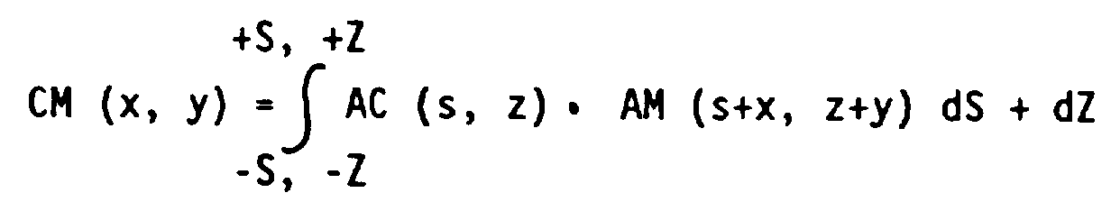
Der x., y.-Wert des Verschiebungsvektors muß dann nur noch genau dem Abbildungsmaßstab der Farbvideokamera umgerechnet werden und ergibt dann den Passerdifferenzvektor bspw. in der Einheit mm.The x., Y. Value of the displacement vector then only has to be converted exactly to the imaging scale of the color video camera and then results in the register difference vector, for example, in the unit mm.
Die Berechnung der Kreuzkorrelationsfunktion läßt sich auf eine Dimension reduzieren, d.h. die Integration erstreckt sich nur über die Spalten bzw. Zeilenrichtung, wenn die Kontur der Bildstelle senkrecht zur Spalten- bzw. Zeilenrichtung verläuft. Nach Fig. 1c) verläuft die Richtung der Kontur senkrecht zur Richtung der Bildzeilen - die Integration erfolgt somit in jeder Bildzeile über die Spaltenrichtung, d.h. quer zur Kontur.The calculation of the cross correlation function can be reduced to one dimension, i.e. the integration extends only over the columns or row direction if the contour of the image point is perpendicular to the column or row direction. According to Fig. 1c), the direction of the contour is perpendicular to the direction of the image lines - the integration is thus carried out in each image line via the column direction, i.e. across the contour.
Mit dem bisher beschriebenen Verfahren und den entsprechenden Vorrichtungselementen lassen sich Passerdifferenzen im Bild des Druckbogens an mehreren Konturen aufweisenden Druckbildstellen bestimmen. Um aus diesen Passerdifferenzen der entsprechenden Teilbilder zueinander die nötigen Registerverstellungen zu bestimmen, ist es nun nur noch nötig, die X-, Y-Koordinaten jeder Messtelle, d.h. der Druckbildstelle auf dem Druckbogen zu bestimmen. Dazu wird der Druckbogen, wie bei der Farbabrüstung möglich auf eine flache Unterlage gelegt und mit den Kanten einer Druckbogenecke in einen Anschlag positioniert. Eine derartige Positionierung eines Druckbogens auf einer Unterlage ist bei Farbabstimmpulten mit traversierenden Farbdichtemessköpfen Stand der Technik. Zur Bestimmung der X-, Y-Koordinaten der Messtellen kann die Farbvideokamera 2 mechanisch über den Druckbogen geführt sein, beispielsweise ähnlich wie der Zeichenstift eines Zeichenplotters. Durch in den Führungselementen angebrachte Positionsgeber erfolgt dann die Bestimmung der X-, Y-Koordinaten der Meßstelle auf den Druckbogen. Auch eine Führung in der Art eines Mehrgelenks ist denkbar. Die Bestimmung der Position der Farbvideokamera 2 auf dem Druckbogen erfolgt dann durch in den Drehgelenken des Mehrgelenks angebrachte Drehwinkelgeber.With the method described up to now and the corresponding device elements, register differences in the image of the printed sheet can be determined at print image locations having several contours. In order to determine the necessary register adjustments from these register differences of the corresponding partial images to one another, it is now only necessary to determine the X, Y coordinates of each measuring point, ie the printing image point on the printing sheet. For this purpose, the printing sheet is placed on a flat surface, as is possible with the color degradation, and positioned with the edges of a printing sheet corner in a stop. Such positioning of a print sheet on a base is in the case of color control desks with traversing color density measuring heads State of the art. To determine the X, Y coordinates of the measuring points, the
Die X-, Y-Koordinaten der Messtellen sowie die in diesen durch den Bildrechner 7 errechneten Passerdifferenzen der einzelnen Teilbilder zueinander können dann einen Registerrechner 10 zugeführt werden, der aus diesen Werten nötige Verstellungen für das Seiten-, Umfangs- und Diagonalregister in den einzelnen Druckwerken errechnet und in einer weiteren Ausgestaltung auch in Form von Steuerbefehlen an Registerverstelleinrichtungen dieser Druckwerke weiterleitet. Dies ist in Figur 2a) durch die Pfeile bei Registerrechner 10 angedeutet.The X, Y coordinates of the measuring points and the register differences of the individual partial images to one another in these, calculated by the
Werden Passerdifferenzen an mehreren Bildstellen ermittelt, so können Bildstellen mit verschiedenen Gewichtsfaktoren versehen werden und der Registerrechner 10 aus den entsprechenden Passerdifferenzen eine für alle Messtellen optimale Registerverstellung errechnen. Dies ist insbesondere dann von Vorteil, wenn, wie häufig an Mehrfarbenoffsetdruckprodukten feststellbar, Passerdifferenzen im Bild nicht gleichförmig über den Bogen verteilt sind, sondern vielmehr bestimmte Stellen mehr oder weniger passen, andere wiederum Passerdifferenzen zeigen. Registerverstellungen können dann nur als ein optimaler Kompromiß vorgenommen werden.If register differences are determined at several image locations, image locations can be provided with different weighting factors and the
- 11
- DruckbogenPrinted sheet
- 1.11.1
- FarbkontrollstreifenColor control strips
- 22nd
- FarbvideokameraColor video camera
- 2.12.1
- MakrooptikMacro optics
- 2.22.2
- bildwandelndes Elementimage-changing element
- 2.32.3
- StützelementSupport element
- 2.42.4
- BeleuchtungseinrichtungLighting device
- 2.52.5
- SignalwandlerSignal converter
- 33rd
- FarbmonitorColor monitor
- 44th
- BildspeicherImage storage
- 55
- FarbauszugsrechnerColor separation calculator
- 5.15.1
- FarbwertspeicherColor value memory
- 66
- FarbauszugsspeicherColor separation memory
- 77
- BildrechnerImage calculator
- 88th
- Tastaturkeyboard
- 99
- BedienelementControl element
- 1010th
- RegisterrechnerRegister calculator
Claims (18)
- Process for determining matching differences at printed image positions of a multi-colour offset print, in which a printed image position is viewed enlarged by means of a colour video camera, whereby a printed image position is sensed which has a contour which has arisen by the superimposed printing of at least two different printing inks and which is evident as a brightness and/or colour difference, the image of this printed image position is converted from the colour space of the colour video camera into the colour space of the printing inks used in the print and accordingly is broken down into these colour separations and the determination of the matching differences takes place from a determination of the offset of the contours in the individual colour separations relative to one another.
- Process according to Claim 1, in which the breakdown of the printed image position into colour separations takes place in the RGB colour space of the colour video camera (2).
- Process according to Claim 1, in which the breakdown of the printed image position into colour separation takes place in the HSI colour system.
- Process according to Claim 2 or 3, in which in each colour separation, raster points below a given raster point size are eliminated.
- Process according to one of the preceding Claims, in which in each colour separation regions with raster points above a given raster point size are filled in to a full tone surface and a boundary line relative to the remaining image area is formed in the respective colour separation.
- Process according to one of the preceding Claims, in which in each colour separation a boundary line is formed which separates a region with raster points above a given raster point size from the remaining image areas of the colour separation.
- Process according to Claim 5 or 6, in which the register difference results by calculation of displacement factors of the boundary lines in the different colour separations relative to one another.
- Process according to Claim 5 or 6, in which the register difference determination takes place by working out the necessary displacement of the colour separations corresponding to the printing inks used in the print relative to one another, until the boundary lines in the individual colour separations correlate with one another.
- Process according to one of Claims 1 to 4, in which the register difference is determined from an extreme value of a correlation calculation of the image contents of the individual colour separations relative to one another.
- Device for carrying out the process in accordance with one of Claims 1 to 9 with a colour video camera (2) for capturing a printed image position, a subsequently connected image processing unit (5-7) as well as a colour monitor (3) for the enlarged representation of the printed image position, wherein the colour processing unit (5-7) has a colour separation calculator (5) with which a printed image position, which has a contour and which has arisen from the superimposed printing of at least two printing inks can be transformed from the colour space of the video camera (2) into the colour space constituted by the printing inks used in the printing and can be broken down into the corresponding colour separations, and the image processing unit (5-7) has a colour separation store (6) in the units of which the colour separations corresponding to the partial images can be stored and the image processing unit (5-7) has an image calculator (7) which is constructed to calculate the displacement of the individual contours in the colour separations corresponding to the partial images and to determine the register difference therefrom.
- Device according to Claim 10, in which the colour video camera (2) has connected to it a signal convertor (2.5) by which the signal carrying the image information of the printed image position can be extracted in the form of digital RGB or HSI values.
- Device according to Claim 10 or 11, in which an image store (4) is provided in which the image of the printed image position is storable.
- Device according to Claim 11 or 12, in which a colour value store (5.1) is provided in which the RGB or HSI values of the printing inks used in the print are storable.
- Device according to Claim 11, in which in the colour value store (5.1) the RGB or HSI values of the printing inks are storable individually and in superimposed printing, determined by a calibration measurement with the colour video camera (2) on a colour control strip (1.1) printed at the same time.
- Device according to one of the preceding Claims, in which a keyboard (8) and/or an interface element (9) is provided with which via image convertor (7) on the ink monitor (3), the printed image position is displayable as colour separations individually chosen as desired or superimposed in sequence chosen as desired.
- Device according to one of the preceding Claims, in which the colour video camera (2) is constructed as a single chip or three chip diode array camera.
- Device according to one of the preceding Claims, in which the colour video camera (2) has illumination devices (2.4) for illuminating the printed image position and is positionable by means of support elements (2.3) at a distance above the printed sheet (1) leading to a defined enlargement of the printed image position on the colour monitor (3).
- Device according to one of the preceding Claims, in which means are provided with which the coordinates of the printed image position captured by the colour video camera (2) are determined on the printed sheet (1), in which a register calculator (10) is provided to which these coordinates of the printed image position as well as the register differences determined therefrom in the image calculator (7) can be fed and the register calculator (10) is constructed in order to calculate from the coordinates of the printed image position together with the register differences register adjustments, wherein these can be shown on the colour monitor (3) and/or can be fed directly in the form of control data to the register adjustment devices in the individual printing units.
Applications Claiming Priority (2)
| Application Number | Priority Date | Filing Date | Title |
|---|---|---|---|
| DE4012608A DE4012608A1 (en) | 1990-04-20 | 1990-04-20 | METHOD AND DEVICE FOR DETERMINING PASSAGE DIFFERENCES AT PRINT IMAGE SITES OF A MULTICOLOR OFFSET PRINT |
| DE4012608 | 1990-04-20 |
Publications (3)
| Publication Number | Publication Date |
|---|---|
| EP0452700A2 EP0452700A2 (en) | 1991-10-23 |
| EP0452700A3 EP0452700A3 (en) | 1992-11-25 |
| EP0452700B1 true EP0452700B1 (en) | 1996-05-01 |
Family
ID=6404731
Family Applications (1)
| Application Number | Title | Priority Date | Filing Date |
|---|---|---|---|
| EP91104525A Expired - Lifetime EP0452700B1 (en) | 1990-04-20 | 1991-03-22 | Method and device for determining compass differences of printing image positions of a multicolour offset printing |
Country Status (5)
| Country | Link |
|---|---|
| US (1) | US5181257A (en) |
| EP (1) | EP0452700B1 (en) |
| JP (1) | JP3053893B2 (en) |
| AT (1) | ATE137629T1 (en) |
| DE (2) | DE4012608A1 (en) |
Cited By (1)
| Publication number | Priority date | Publication date | Assignee | Title |
|---|---|---|---|---|
| DE102007031058A1 (en) | 2007-07-04 | 2009-01-08 | Manroland Ag | Method and device for the application of functional elements |
Families Citing this family (69)
| Publication number | Priority date | Publication date | Assignee | Title |
|---|---|---|---|---|
| JP2836930B2 (en) * | 1990-07-13 | 1998-12-14 | 三菱重工業株式会社 | Register adjustment method and device |
| EP0505323B2 (en) * | 1991-03-21 | 2001-11-07 | Maschinenfabrik Wifag | Method of adjusting the screendot sizes of a rotary offset printing machine |
| CH684590A5 (en) * | 1991-09-26 | 1994-10-31 | Grapha Holding Ag | Process for uniformity testing of printed sheets and apparatus thereof for implementation. |
| US5841955A (en) * | 1991-12-02 | 1998-11-24 | Goss Graphic Systems, Inc. | Control system for a printing press |
| US5412577A (en) * | 1992-10-28 | 1995-05-02 | Quad/Tech International | Color registration system for a printing press |
| US5313570A (en) * | 1993-03-31 | 1994-05-17 | Miles, Inc. | Method for determining color boundaries for correcting for plate misregistration in color printing |
| US5408535A (en) * | 1993-09-07 | 1995-04-18 | Miles Inc. | Video test strip reader and method for evaluating test strips |
| US5365847A (en) * | 1993-09-22 | 1994-11-22 | Rockwell International Corporation | Control system for a printing press |
| DE4335351C2 (en) * | 1993-10-16 | 2003-04-30 | Heidelberger Druckmasch Ag | Method and device for compensating register deviations in an offset rotary printing machine |
| DE4335350A1 (en) * | 1993-10-16 | 1995-04-20 | Heidelberger Druckmasch Ag | Process and device for determining register deviations in multicolour printed products produced in a printing machine |
| US5732162A (en) * | 1993-10-28 | 1998-03-24 | Xerox Corporation | Two dimensional linearity and registration error correction in a hyperacuity printer |
| DE4403861C2 (en) * | 1994-02-08 | 1998-08-20 | Heidelberger Druckmasch Ag | Method for producing a multicolored print with a printing press in at least two different runs |
| DE19526373B4 (en) * | 1994-08-08 | 2005-10-20 | Tokyo Kikai Seisakusho Ltd | Apparatus for register control in web-fed rotary printing presses and automatic method for register control for web-fed rotary presses for correction of registration errors |
| US5812705A (en) * | 1995-02-28 | 1998-09-22 | Goss Graphic Systems, Inc. | Device for automatically aligning a production copy image with a reference copy image in a printing press control system |
| DE19519276A1 (en) * | 1995-05-22 | 1996-11-28 | Innomess Elektronik Gmbh | Colour mixing determn. method with multi-colour printing using image sensor |
| JP4114959B2 (en) * | 1995-06-20 | 2008-07-09 | キヤノン株式会社 | Image processing method and apparatus |
| US5767980A (en) | 1995-06-20 | 1998-06-16 | Goss Graphic Systems, Inc. | Video based color sensing device for a printing press control system |
| US5805280A (en) * | 1995-09-28 | 1998-09-08 | Goss Graphic Systems, Inc. | Control system for a printing press |
| US5903712A (en) * | 1995-10-05 | 1999-05-11 | Goss Graphic Systems, Inc. | Ink separation device for printing press ink feed control |
| EP0770480B1 (en) * | 1995-10-25 | 2001-12-19 | Heidelberger Druckmaschinen Aktiengesellschaft | Printing press with register control system |
| IT1284432B1 (en) * | 1996-03-22 | 1998-05-21 | De La Rue Giori Sa | PROCEDURE FOR AUTOMATIC CHECK OF THE PRINT QUALITY OF A POLYCHROME IMAGE |
| US5819655A (en) * | 1997-08-20 | 1998-10-13 | Bristol-Myers Squibb Company | Cyclinder color printing method and product using improved misregistration detection |
| FR2775930B1 (en) * | 1998-03-11 | 2000-06-02 | Heidelberger Druckmasch Ag | DEVICE FOR CONTROLLING THE PRINTING OF MATERIAL TAPE IN A ROTARY PRINTING MACHINE |
| US5974967A (en) * | 1998-08-27 | 1999-11-02 | Lenticulartechnologies, L.L.C. | Registration system for lenticular printing |
| US6571021B1 (en) * | 1999-01-29 | 2003-05-27 | International Business Machines Corporation | Recovering an invisible digital image from a distorted image replica |
| US6778698B1 (en) * | 1999-06-11 | 2004-08-17 | Pts Corporation | Method and apparatus for digital image segmentation |
| US6718878B2 (en) * | 1999-09-29 | 2004-04-13 | Xerox Corporation | Automatic detection of black and white pages in a color document stream |
| DE10049752A1 (en) | 1999-10-11 | 2001-05-10 | Heidelberger Druckmasch Ag | Procedure for exploring the precision of marking and placing edges, folds or cuts on printed samples, comprises use of detector such as CCD camera and hatched field to find jumps in contrast |
| US6874420B2 (en) * | 1999-10-22 | 2005-04-05 | Cc1, Inc. | System and method for register mark recognition |
| US6523467B2 (en) * | 1999-12-17 | 2003-02-25 | Heidelberger Druckmaschinen Aktiengesellschaft | Method for measuring engraving cups |
| DE50113849D1 (en) * | 2000-05-17 | 2008-05-29 | Eastman Kodak Co | Device for minimizing the influence of register differences |
| US6543350B2 (en) * | 2000-05-19 | 2003-04-08 | Intelligent Sensing, Inc. | Measurement system to monitor printing contact pressure |
| DE10027856C2 (en) * | 2000-06-06 | 2002-09-19 | Bst Servo Technik Gmbh | Method and device for reading register marks |
| US6796240B2 (en) | 2001-06-04 | 2004-09-28 | Quad/Tech, Inc. | Printing press register control using colorpatch targets |
| FR2825817B1 (en) * | 2001-06-07 | 2003-09-19 | Commissariat Energie Atomique | IMAGE PROCESSING METHOD FOR THE AUTOMATIC EXTRACTION OF SEMANTIC ELEMENTS |
| DE10149158B4 (en) * | 2001-10-04 | 2010-07-22 | Wifag Maschinenfabrik Ag | Method and device for determining the position of a printed paper web |
| US7013803B2 (en) | 2002-02-06 | 2006-03-21 | Quad/Tech, Inc. | Color registration control system for a printing press |
| US7253929B2 (en) * | 2002-02-06 | 2007-08-07 | Quad/Tech, Inc. | Camera assembly for a printing press |
| US20030147090A1 (en) * | 2002-02-06 | 2003-08-07 | Quad/Tech, Inc. | Camera assembly for a printing press |
| US6684773B2 (en) | 2002-03-21 | 2004-02-03 | Lexmark International, Inc. | Target and algorithm for color laser printhead alignment |
| US7133563B2 (en) * | 2002-10-31 | 2006-11-07 | Microsoft Corporation | Passive embedded interaction code |
| US7116840B2 (en) | 2002-10-31 | 2006-10-03 | Microsoft Corporation | Decoding and error correction in 2-D arrays |
| DE10261059B4 (en) * | 2002-12-24 | 2006-04-13 | Eltromat Gmbh | Method and device for measuring and controlling a longitudinal and side register and a print image parallelism of a printing register in a multi-color printing machine |
| US6810813B2 (en) * | 2003-03-14 | 2004-11-02 | Heidelberger Druckmaschinen Ag | Device and method for controlling registration in a printing press |
| DE10319770A1 (en) * | 2003-05-02 | 2004-12-09 | Koenig & Bauer Ag | Method for regulating the color density of a color applied by a printing press to a printing medium and device for regulating various parameters relevant for the printing process of a printing press |
| DE10333626A1 (en) * | 2003-07-24 | 2005-02-17 | Robert Bürkle GmbH | Device for printing on flat workpieces |
| US7583842B2 (en) * | 2004-01-06 | 2009-09-01 | Microsoft Corporation | Enhanced approach of m-array decoding and error correction |
| US7263224B2 (en) * | 2004-01-16 | 2007-08-28 | Microsoft Corporation | Strokes localization by m-array decoding and fast image matching |
| US7607076B2 (en) | 2005-02-18 | 2009-10-20 | Microsoft Corporation | Embedded interaction code document |
| US7826074B1 (en) | 2005-02-25 | 2010-11-02 | Microsoft Corporation | Fast embedded interaction code printing with custom postscript commands |
| US20060215913A1 (en) * | 2005-03-24 | 2006-09-28 | Microsoft Corporation | Maze pattern analysis with image matching |
| US20060242562A1 (en) * | 2005-04-22 | 2006-10-26 | Microsoft Corporation | Embedded method for embedded interaction code array |
| US7421439B2 (en) | 2005-04-22 | 2008-09-02 | Microsoft Corporation | Global metadata embedding and decoding |
| US7542976B2 (en) * | 2005-04-22 | 2009-06-02 | Microsoft Corporation | Local metadata embedding and decoding |
| US7599560B2 (en) | 2005-04-22 | 2009-10-06 | Microsoft Corporation | Embedded interaction code recognition |
| US7400777B2 (en) * | 2005-05-25 | 2008-07-15 | Microsoft Corporation | Preprocessing for information pattern analysis |
| US7729539B2 (en) * | 2005-05-31 | 2010-06-01 | Microsoft Corporation | Fast error-correcting of embedded interaction codes |
| US7580576B2 (en) * | 2005-06-02 | 2009-08-25 | Microsoft Corporation | Stroke localization and binding to electronic document |
| US7619607B2 (en) | 2005-06-30 | 2009-11-17 | Microsoft Corporation | Embedding a pattern design onto a liquid crystal display |
| US7622182B2 (en) | 2005-08-17 | 2009-11-24 | Microsoft Corporation | Embedded interaction code enabled display |
| US7817816B2 (en) * | 2005-08-17 | 2010-10-19 | Microsoft Corporation | Embedded interaction code enabled surface type identification |
| JP2007173912A (en) * | 2005-12-19 | 2007-07-05 | Glory Ltd | Print inspection apparatus |
| US20080001614A1 (en) * | 2006-06-28 | 2008-01-03 | Thorson Dean E | Image Capture Device with Alignment Indicia |
| FR2910372B1 (en) * | 2006-12-21 | 2010-12-10 | Goss Int Montataire Sa | DEVICE FOR CONTROLLING A ROTARY PRESS OF PRINTING A WEB OF MATERIAL, AND ROTATING PRESS. |
| DE102007007827A1 (en) * | 2007-02-16 | 2008-08-21 | Bst International Gmbh | Method and device for checking a printed image |
| DE102007049679B4 (en) * | 2007-10-17 | 2013-10-17 | Robert Bosch Gmbh | Marking sensor and method for evaluating marks |
| DE102009023948B4 (en) | 2009-06-04 | 2013-05-29 | Baumer Innotec Ag | Device for detecting a mark on a flat object and method therefor, and device for separating sections from a flat object |
| DE102013109920A1 (en) * | 2013-09-10 | 2015-03-12 | Manroland Web Systems Gmbh | Method for printing a substrate |
| DE102015219245B3 (en) * | 2015-10-06 | 2016-11-17 | Heidelberger Druckmaschinen Ag | Method for efficient paper strain compensation |
Citations (1)
| Publication number | Priority date | Publication date | Assignee | Title |
|---|---|---|---|---|
| EP0296602A1 (en) * | 1987-06-26 | 1988-12-28 | Tektronix, Inc. | Component television timing corrector |
Family Cites Families (15)
| Publication number | Priority date | Publication date | Assignee | Title |
|---|---|---|---|---|
| GB2115145B (en) * | 1981-07-29 | 1986-05-29 | Dainippon Printing Co Ltd | Method and device for inspecting printed matter |
| JPS5837647A (en) * | 1981-08-28 | 1983-03-04 | Dainippon Screen Mfg Co Ltd | Formation of blanking mask |
| EP0079153B1 (en) * | 1981-10-30 | 1985-08-21 | Crosfield Electronics Limited | Controlling register in a printing press |
| DE3380997D1 (en) * | 1982-08-31 | 1990-01-25 | Dainippon Printing Co Ltd | IMAGE EXAMINATION METHOD. |
| DE3481595D1 (en) * | 1983-06-02 | 1990-04-19 | Wales R Langdon | REGISTER CONTROL IN A CLOSED LOOP. |
| JPS6184249A (en) * | 1984-10-03 | 1986-04-28 | Dainippon Printing Co Ltd | Misregistration measuring device for prints |
| EP0177885A3 (en) * | 1984-10-03 | 1988-02-24 | Dai Nippon Insatsu Kabushiki Kaisha | Method and device for registering printing press |
| EP0194331B1 (en) * | 1985-03-14 | 1990-07-18 | Toppan Printing Co., Ltd. | Inspecting device for print |
| US4882764A (en) * | 1985-03-29 | 1989-11-21 | Quad/Tech, Inc. | Cutoff control system |
| JPS6297846A (en) * | 1985-10-25 | 1987-05-07 | Dainippon Printing Co Ltd | Method for measuring amount of register error in printed matter |
| DE3770316D1 (en) * | 1986-04-18 | 1991-07-04 | Heidelberger Druckmasch Ag | DETERMINING THE MULTI-COLOR PRINT REGISTER ERROR. |
| CA1305235C (en) * | 1986-10-31 | 1992-07-14 | Bruce A. Reynolds | Cutoff control system |
| US4742233A (en) * | 1986-12-22 | 1988-05-03 | American Telephone And Telgraph Company | Method and apparatus for automated reading of vernier patterns |
| DE3719766A1 (en) * | 1987-06-13 | 1988-12-22 | Heidelberger Druckmasch Ag | REGISTER MEASURING SYSTEM |
| US5018213A (en) * | 1988-05-11 | 1991-05-21 | Web Printing Controls Co., Inc. | Method and apparatus for registration mark identification |
-
1990
- 1990-04-20 DE DE4012608A patent/DE4012608A1/en active Granted
-
1991
- 1991-03-22 DE DE59107746T patent/DE59107746D1/en not_active Expired - Fee Related
- 1991-03-22 AT AT91104525T patent/ATE137629T1/en not_active IP Right Cessation
- 1991-03-22 EP EP91104525A patent/EP0452700B1/en not_active Expired - Lifetime
- 1991-04-19 JP JP3088220A patent/JP3053893B2/en not_active Expired - Fee Related
- 1991-04-22 US US07/689,200 patent/US5181257A/en not_active Expired - Lifetime
Patent Citations (1)
| Publication number | Priority date | Publication date | Assignee | Title |
|---|---|---|---|---|
| EP0296602A1 (en) * | 1987-06-26 | 1988-12-28 | Tektronix, Inc. | Component television timing corrector |
Cited By (2)
| Publication number | Priority date | Publication date | Assignee | Title |
|---|---|---|---|---|
| DE102007031058A1 (en) | 2007-07-04 | 2009-01-08 | Manroland Ag | Method and device for the application of functional elements |
| EP2025514A2 (en) | 2007-07-04 | 2009-02-18 | manroland AG | Method and device for applying functional elements |
Also Published As
| Publication number | Publication date |
|---|---|
| EP0452700A2 (en) | 1991-10-23 |
| DE4012608A1 (en) | 1991-10-24 |
| US5181257A (en) | 1993-01-19 |
| JPH04224961A (en) | 1992-08-14 |
| DE4012608C2 (en) | 1992-07-02 |
| EP0452700A3 (en) | 1992-11-25 |
| DE59107746D1 (en) | 1996-06-05 |
| ATE137629T1 (en) | 1996-05-15 |
| JP3053893B2 (en) | 2000-06-19 |
Similar Documents
| Publication | Publication Date | Title |
|---|---|---|
| EP0452700B1 (en) | Method and device for determining compass differences of printing image positions of a multicolour offset printing | |
| DE102017220361B4 (en) | Method and test pattern for detecting and compensating for failed printing nozzles in an inkjet printing machine | |
| EP0096084B1 (en) | Process to avoid image defects in multicolour printing caused by non coincident printing of the colour separations | |
| EP0353228B1 (en) | Process for positioning plate cylinders in a multicolour rotary printing press | |
| WO1980002607A1 (en) | Switching process and device by partial electronic retouching during the reproduction of colour images | |
| EP0059951A2 (en) | Method of reproducing four colours polychrome copies with colour removal | |
| CH645998A5 (en) | METHOD FOR COLOR EVALUATING SAMPLES AND COLOR EVALUATION DEVICE FOR CARRYING OUT THE METHOD. | |
| DE4335350A1 (en) | Process and device for determining register deviations in multicolour printed products produced in a printing machine | |
| EP1759845B1 (en) | Control process for printing methods | |
| WO1982000902A1 (en) | Method and circuit for partial correction of the drawing during the colour image reproduction | |
| DD274786A1 (en) | METHOD AND ARRANGEMENT FOR MONITORING THE PRINT QUALITY OF MULTI-COLOR RASTER PRINTING TEMPLATES OF AN OFFSET PRINTING MACHINE | |
| AT501210A2 (en) | DEVICE FOR QUALITY CONTROL OF SURFACE VARIABLE PRINTING SIZES | |
| EP2127877B1 (en) | Method for measuring the colour register in a printer | |
| DE4338976C2 (en) | Arrangement of several control fields | |
| EP0060243B1 (en) | Method and circuit for the partial correction in colour image reproduction | |
| DE102019211758A1 (en) | Passer register measurement with circular measuring marks | |
| DE102010049945A1 (en) | Method for detecting geometric errors of printed image, involves measuring reference position on substrate with measuring device | |
| EP0129768B1 (en) | Colour density measuring device | |
| EP0920994A2 (en) | Method of determination of colour values | |
| DE3942254C2 (en) | ||
| EP0916491A1 (en) | Method for the determination of colorimetric gradients | |
| DE102018216442A1 (en) | Register measurement without register marks | |
| CH698940B1 (en) | Method and apparatus for automatic determination of presetting values for ink-zone adjusting elements of an inking unit of a printing press. | |
| DE19914913A1 (en) | Determining overfill parameters for printed pages involves determining test element pattern shift between two color printouts and using to compute optimum overfill width | |
| DE10101137B4 (en) | Method for raster-adaptive copy retouching |
Legal Events
| Date | Code | Title | Description |
|---|---|---|---|
| PUAI | Public reference made under article 153(3) epc to a published international application that has entered the european phase |
Free format text: ORIGINAL CODE: 0009012 |
|
| AK | Designated contracting states |
Kind code of ref document: A2 Designated state(s): AT BE CH DE ES FR GB IT LI NL SE |
|
| PUAL | Search report despatched |
Free format text: ORIGINAL CODE: 0009013 |
|
| AK | Designated contracting states |
Kind code of ref document: A3 Designated state(s): AT BE CH DE ES FR GB IT LI NL SE |
|
| 17P | Request for examination filed |
Effective date: 19921030 |
|
| 17Q | First examination report despatched |
Effective date: 19941020 |
|
| GRAA | (expected) grant |
Free format text: ORIGINAL CODE: 0009210 |
|
| AK | Designated contracting states |
Kind code of ref document: B1 Designated state(s): AT BE CH DE ES FR GB IT LI NL SE |
|
| PG25 | Lapsed in a contracting state [announced via postgrant information from national office to epo] |
Ref country code: NL Free format text: LAPSE BECAUSE OF FAILURE TO SUBMIT A TRANSLATION OF THE DESCRIPTION OR TO PAY THE FEE WITHIN THE PRESCRIBED TIME-LIMIT Effective date: 19960501 Ref country code: ES Free format text: THE PATENT HAS BEEN ANNULLED BY A DECISION OF A NATIONAL AUTHORITY Effective date: 19960501 Ref country code: IT Free format text: LAPSE BECAUSE OF FAILURE TO SUBMIT A TRANSLATION OF THE DESCRIPTION OR TO PAY THE FEE WITHIN THE PRESCRIBED TIME-LIMIT;WARNING: LAPSES OF ITALIAN PATENTS WITH EFFECTIVE DATE BEFORE 2007 MAY HAVE OCCURRED AT ANY TIME BEFORE 2007. THE CORRECT EFFECTIVE DATE MAY BE DIFFERENT FROM THE ONE RECORDED. Effective date: 19960501 |
|
| REF | Corresponds to: |
Ref document number: 137629 Country of ref document: AT Date of ref document: 19960515 Kind code of ref document: T |
|
| ET | Fr: translation filed | ||
| REG | Reference to a national code |
Ref country code: CH Ref legal event code: NV Representative=s name: E. BLUM & CO. PATENTANWAELTE |
|
| GBT | Gb: translation of ep patent filed (gb section 77(6)(a)/1977) |
Effective date: 19960508 |
|
| REF | Corresponds to: |
Ref document number: 59107746 Country of ref document: DE Date of ref document: 19960605 |
|
| NLV1 | Nl: lapsed or annulled due to failure to fulfill the requirements of art. 29p and 29m of the patents act | ||
| PLBE | No opposition filed within time limit |
Free format text: ORIGINAL CODE: 0009261 |
|
| STAA | Information on the status of an ep patent application or granted ep patent |
Free format text: STATUS: NO OPPOSITION FILED WITHIN TIME LIMIT |
|
| 26N | No opposition filed | ||
| PGFP | Annual fee paid to national office [announced via postgrant information from national office to epo] |
Ref country code: SE Payment date: 19980219 Year of fee payment: 8 |
|
| PGFP | Annual fee paid to national office [announced via postgrant information from national office to epo] |
Ref country code: AT Payment date: 19980223 Year of fee payment: 8 |
|
| PGFP | Annual fee paid to national office [announced via postgrant information from national office to epo] |
Ref country code: BE Payment date: 19980320 Year of fee payment: 8 |
|
| PG25 | Lapsed in a contracting state [announced via postgrant information from national office to epo] |
Ref country code: AT Free format text: LAPSE BECAUSE OF NON-PAYMENT OF DUE FEES Effective date: 19990322 |
|
| PG25 | Lapsed in a contracting state [announced via postgrant information from national office to epo] |
Ref country code: SE Free format text: LAPSE BECAUSE OF NON-PAYMENT OF DUE FEES Effective date: 19990323 |
|
| PG25 | Lapsed in a contracting state [announced via postgrant information from national office to epo] |
Ref country code: BE Free format text: LAPSE BECAUSE OF NON-PAYMENT OF DUE FEES Effective date: 19990331 |
|
| BERE | Be: lapsed |
Owner name: MAN ROLAND DRUCKMASCHINEN A.G. Effective date: 19990331 |
|
| EUG | Se: european patent has lapsed |
Ref document number: 91104525.0 |
|
| EUG | Se: european patent has lapsed |
Ref document number: 91104525.0 |
|
| REG | Reference to a national code |
Ref country code: GB Ref legal event code: IF02 |
|
| PGFP | Annual fee paid to national office [announced via postgrant information from national office to epo] |
Ref country code: GB Payment date: 20030226 Year of fee payment: 13 |
|
| PG25 | Lapsed in a contracting state [announced via postgrant information from national office to epo] |
Ref country code: GB Free format text: LAPSE BECAUSE OF NON-PAYMENT OF DUE FEES Effective date: 20040322 |
|
| GBPC | Gb: european patent ceased through non-payment of renewal fee |
Effective date: 20040322 |
|
| REG | Reference to a national code |
Ref country code: CH Ref legal event code: PFA Owner name: MAN ROLAND DRUCKMASCHINEN AG Free format text: MAN ROLAND DRUCKMASCHINEN AG#POSTFACH 10 12 64#D-63012 OFFENBACH (DE) -TRANSFER TO- MAN ROLAND DRUCKMASCHINEN AG#POSTFACH 10 12 64#D-63012 OFFENBACH (DE) |
|
| PGFP | Annual fee paid to national office [announced via postgrant information from national office to epo] |
Ref country code: CH Payment date: 20080314 Year of fee payment: 18 |
|
| PGFP | Annual fee paid to national office [announced via postgrant information from national office to epo] |
Ref country code: DE Payment date: 20080321 Year of fee payment: 18 Ref country code: FR Payment date: 20080314 Year of fee payment: 18 |
|
| REG | Reference to a national code |
Ref country code: CH Ref legal event code: PFA Owner name: MANROLAND AG Free format text: MAN ROLAND DRUCKMASCHINEN AG#POSTFACH 10 12 64#D-63012 OFFENBACH (DE) -TRANSFER TO- MANROLAND AG#MUEHLHEIMER STRASSE 341#63075 OFFENBACH (DE) |
|
| REG | Reference to a national code |
Ref country code: FR Ref legal event code: CD |
|
| REG | Reference to a national code |
Ref country code: CH Ref legal event code: PL |
|
| REG | Reference to a national code |
Ref country code: FR Ref legal event code: ST Effective date: 20091130 |
|
| PG25 | Lapsed in a contracting state [announced via postgrant information from national office to epo] |
Ref country code: LI Free format text: LAPSE BECAUSE OF NON-PAYMENT OF DUE FEES Effective date: 20090331 Ref country code: CH Free format text: LAPSE BECAUSE OF NON-PAYMENT OF DUE FEES Effective date: 20090331 Ref country code: DE Free format text: LAPSE BECAUSE OF NON-PAYMENT OF DUE FEES Effective date: 20091001 |
|
| PG25 | Lapsed in a contracting state [announced via postgrant information from national office to epo] |
Ref country code: FR Free format text: LAPSE BECAUSE OF NON-PAYMENT OF DUE FEES Effective date: 20091123 |