EP0452674A1 - Cleaning trolley - Google Patents
Cleaning trolley Download PDFInfo
- Publication number
- EP0452674A1 EP0452674A1 EP91103798A EP91103798A EP0452674A1 EP 0452674 A1 EP0452674 A1 EP 0452674A1 EP 91103798 A EP91103798 A EP 91103798A EP 91103798 A EP91103798 A EP 91103798A EP 0452674 A1 EP0452674 A1 EP 0452674A1
- Authority
- EP
- European Patent Office
- Prior art keywords
- cleaning trolley
- trolley according
- central strut
- side brackets
- strut
- Prior art date
- Legal status (The legal status is an assumption and is not a legal conclusion. Google has not performed a legal analysis and makes no representation as to the accuracy of the status listed.)
- Granted
Links
Images


Classifications
-
- B—PERFORMING OPERATIONS; TRANSPORTING
- B62—LAND VEHICLES FOR TRAVELLING OTHERWISE THAN ON RAILS
- B62B—HAND-PROPELLED VEHICLES, e.g. HAND CARTS OR PERAMBULATORS; SLEDGES
- B62B3/00—Hand carts having more than one axis carrying transport wheels; Steering devices therefor; Equipment therefor
- B62B3/10—Hand carts having more than one axis carrying transport wheels; Steering devices therefor; Equipment therefor characterised by supports specially adapted to objects of definite shape
- B62B3/104—Hand carts having more than one axis carrying transport wheels; Steering devices therefor; Equipment therefor characterised by supports specially adapted to objects of definite shape the object being of cylindrical shape, e.g. barrels, buckets, dustbins
-
- A—HUMAN NECESSITIES
- A47—FURNITURE; DOMESTIC ARTICLES OR APPLIANCES; COFFEE MILLS; SPICE MILLS; SUCTION CLEANERS IN GENERAL
- A47L—DOMESTIC WASHING OR CLEANING; SUCTION CLEANERS IN GENERAL
- A47L13/00—Implements for cleaning floors, carpets, furniture, walls, or wall coverings
- A47L13/10—Scrubbing; Scouring; Cleaning; Polishing
- A47L13/50—Auxiliary implements
- A47L13/51—Storing of cleaning tools, e.g. containers therefor
-
- B—PERFORMING OPERATIONS; TRANSPORTING
- B62—LAND VEHICLES FOR TRAVELLING OTHERWISE THAN ON RAILS
- B62B—HAND-PROPELLED VEHICLES, e.g. HAND CARTS OR PERAMBULATORS; SLEDGES
- B62B2202/00—Indexing codes relating to type or characteristics of transported articles
- B62B2202/02—Cylindrically-shaped articles, e.g. drums, barrels, flasks
- B62B2202/028—Buckets
Landscapes
- Engineering & Computer Science (AREA)
- Chemical & Material Sciences (AREA)
- Combustion & Propulsion (AREA)
- Transportation (AREA)
- Mechanical Engineering (AREA)
- Handcart (AREA)
- Automatic Analysis And Handling Materials Therefor (AREA)
- Vehicle Body Suspensions (AREA)
- Supporting Of Heads In Record-Carrier Devices (AREA)
Abstract
Description
Die Erfindung betrifft einen Reinigungswagen zum Transport von Behältern wie Eimern oder dgl., mit einem im wesentlichen aus Seitenbügeln und Querstreben bestehenden Grundgestell, welches mit Lenkrollen und einer zur Aufnahme eines Pressenstativs ausgebildeten Mittelstrebe sowie mit einem Handhabungsbügel versehen ist.The invention relates to a cleaning trolley for transporting containers such as buckets or the like. With a base frame consisting essentially of side brackets and cross struts, which is provided with castors and a center strut designed to accommodate a press stand, and with a handling bracket.
Derartige bekannte Reinigungswagen werden vor allem zum Reinigen größerer Flächen, wie bspw. in Krankenhäusern, Hotels, Büros und dgl., insbesondere zum Naßwischen mit sogenannten Naßwischmops eingesetzt. Ein solcher Reinigungswagen ist i.d.R. mit zwei Eimern bestückt, von denen der eine mit klarem Wasser und der andere mit reinigungs- und/oder desinfektionsmittelhaltigem Wasser gefüllt ist. Der Mopbezug wird nach dem Wischen zunächst in den Eimer mit dem klaren Wasser eingetaucht, um den Schmutz auszuwaschen, und anschließend in den Eimer mit dem Reinigungs- und/oder Desinfektionsmittel eingetaucht. Mit Hilfe einer an der Mittelstrebe angebrachten Presse kann die jeweils überschüssige Flüssigkeit ausgepreßt werden. Danach kann der Mop erneut zum Wischen eingesetzt werden. Je nach Größe der Eimer und nach Verwendungszweck werden derartige Reinigungswagen in verschiedenen Abmessungen und Ausführungen hergestellt. Als nachteilig erweist sich bei diesen bekannten Reinigungswagen, daß sie aufgrund der relativ geringen Stückzahl in den jeweiligen Größen- und Ausführungsvarianten kostenintensiv in der Herstellung sind, da viele verschieden bemessene Einzelteile hergestellt und bevorratet werden müssen. Darüberhinaus ist auch die Montage der Einzelteile bisher aufwendig und teuer, da diese i.d.R. miteinander verschweißt werden. Die Umrüstung eines solchen Reinigungswagens auf einen neuen Verwendungszweck ist aufgrund der Schweißverbindung der einzelnen Bauteile nicht möglich.Known cleaning trolleys of this type are used primarily for cleaning larger areas, such as in hospitals, hotels, offices and the like, in particular for wet wiping with so-called wet mops. Such a cleaning trolley is usually equipped with two buckets, one of which is filled with clear water and the other with water containing cleaning agents and / or disinfectants. After wiping, the mop cover is first immersed in the bucket with the clear water in order to wash out the dirt, and then immersed in the bucket with the cleaning agent and / or disinfectant. With the help of one attached to the central strut Press the excess liquid can be squeezed out. The mop can then be used again for wiping. Depending on the size of the bucket and the intended use, cleaning trolleys of this type are manufactured in various dimensions and designs. A disadvantage of these known cleaning trolleys is that, due to the relatively small number in the respective size and design variants, they are costly to manufacture, since many differently sized individual parts have to be manufactured and kept in stock. In addition, the assembly of the individual parts has so far been complex and expensive, since these are usually welded together. Converting such a cleaning trolley to a new purpose is not possible due to the welded connection of the individual components.
Aufgabe der vorliegenden Erfindung ist die Schaffung eines Reinigungswagens der eingangs genannten Art, welcher aus kostengünstig herstellbaren, gegen Reinigungsmittel unempfindlichen und nach Art eines Bausatzes verwendbaren Teilen leicht zu montieren und ggfs. zu demontieren ist.The object of the present invention is to provide a cleaning trolley of the type mentioned at the outset which is easy to assemble and, if necessary, disassemble from parts which are inexpensive to produce, insensitive to cleaning agents and usable in the manner of a kit.
Diese Aufgabe wird erfindungsgemäß im wesentlichen dadurch gelöst, daß zumindest die Querstreben aus Kunststoff bestehen und die Seitenbügel und die Querstreben lösbar miteinander verbunden sind, Auf diese Weise brauchen bspw. zur Verbreiterung des Reinigungswagens lediglich die Querstreben durch längere Querstreben ersetzt werden, welche kostengünstig aus Kunststoff hergestellt werden können. Ein solcher Reinigungswagen kann daher mit geringem Aufwand auf unterschiedliche Eimergrößen und Verwendungszwecke ausgelegt werden, indem die gleichen Seitenbügel verwendet werden. Auch können gleich breite aber unterschiedlich lange Reinigungswagen montiert werden, indem gleiche Querstreben der unterschiedlich großen Seitenbügel eingesetzt werden. Bei Beschädigung eines einzelnen Bauteils kann dieses Bauteil einfach ersetzt werden, so daß der Reinigungswagen weiterhin benutzt werden kann. Bei Weiterentwicklung einzelner Bauteile oder Bauteilgruppen können diese um- bzw. nachgerüstet werden, so daß der Reinigungswagen stets der aktuellen Entwicklung angepaßt werden kann.This object is essentially achieved in that at least the cross struts are made of plastic and the side brackets and the cross struts are detachably connected to each other can be produced. Such a cleaning trolley can therefore be designed with little effort for different bucket sizes and uses by using the same side bracket. Cleaning trolleys of the same width but of different lengths can also be installed by using the same cross braces on the different sized side brackets. If a single component is damaged, this component can simply be replaced so that the cleaning trolley can continue to be used. When individual components or component groups are developed further, these can be converted or retrofitted so that the cleaning trolley can always be adapted to the current development.
Bei einer besonders vorteilhaften Weiterbildung der Erfindung sind die Seitenbügel mit den Querstreben z.B. im Preßsitz zusammengesteckt oder zusammengeklemmt, wodurch eine besonders einfache und montagegünstige Verbindung gewährleistet ist.In a particularly advantageous development of the invention, the side brackets with the cross struts are e.g. plugged or clamped together in the press fit, which ensures a particularly simple and easy-to-install connection.
Wenn die Mittelstrebe aus Kunststoff besteht und lösbar an den Seitenbügeln angebracht ist, kann diese zum einen kostengünstig in beliebiger Formgebung hergestellt und zum anderen ausgetauscht bzw. zusammen mit verschiedenen Seitenbügeln verwendet werden.If the center strut is made of plastic and is detachably attached to the side brackets, it can be inexpensively manufactured in any shape and, on the other hand, exchanged or used together with different side brackets.
Dabei ist es besonders zweckmäßig, wenn die Mittelstrebe mit den Seitenbügeln z.B. im Preßsitz zusammengesteckt oder zusammengeklemmt ist, um auch insoweit eine einfache Montage und zugleich einen sicheren Halt zu gewährleisten.It is particularly useful if the center strut with the side brackets e.g. is plugged together or clamped together in the press fit in order to ensure easy assembly and at the same time a secure hold.
Um eine besonders stabile und verwindungssteife Befestigung zu erzielen, ist bei einer weiteren Ausgestaltung der Erfindung vorgesehen, daß die Mittelstrebe die Seitenbügel im wesentlichen formschlüssig umgreift.In order to achieve a particularly stable and torsionally rigid fastening, it is provided in a further embodiment of the invention that the central strut essentially engages around the side bracket in a form-fitting manner.
Bei einer weiteren vorteilhaften Ausgestaltung der Erfindung ist die Mittelstrebe mittels Spannelementen an den Seitenbügeln angeklemmt, wodurch eine stabile Rahmenkonstruktion und zugleich eine besonders schnelle und einfache Montage gewährleistet sind.In a further advantageous embodiment of the invention, the central strut is clamped to the side brackets by means of tensioning elements, as a result of which a stable frame construction and, at the same time, particularly fast and simple assembly are ensured.
Eine einfache und wirkungsvolle Montagesicherung für die Mittelstrebe wird bei einer weiteren vorteilhaften Ausgestaltung der Erfindung dadurch erzielt, daß die Mittelstrebe mittels eines Sicherungsstiftes oder dgl. an den Seitenbügeln gesichert ist.In a further advantageous embodiment of the invention, simple and effective assembly securing for the central strut is achieved in that the central strut is secured to the side brackets by means of a securing pin or the like.
Besonders vorteilhaft ist es, wenn die Mittelstrebe zugleich zur Aufnahme des Handhabungsbügels dient, welche an dieser angesteckt oder angeklemmt werden kann. Auf diese Weise kann auf zusätzliche Befestigungselemente verzichtet werden.It is particularly advantageous if the central strut serves at the same time to accommodate the handle, which can be attached or clamped to it. In this way, additional fastening elements can be dispensed with.
Es hat sich bei Reinigungswagen als zweckmäßig erwiesen, den Handhabungsbügel verschwenkbar zwischen Anschlägen zu führen, um den Reinigungswagen in beide Fahrtrichtungen ziehen bzw. schieben zu können und um die Zugänglichkeit zu den Eimern zu verbessern. Es ist daher besonders vorteilhaft, die Anschläge für den Handhabungsbügel, wie bei einer weiteren vorteilhaften Ausgestaltung der Erfindung, ebenfalls an der Mittelstreben vorzusehen.It has proven to be expedient in cleaning trolleys to pivot the handling bracket between stops in order to be able to pull or push the cleaning trolley in both directions of travel and to improve the accessibility to the buckets. It is therefore particularly advantageous to also provide the stops for the handling bracket, as in a further advantageous embodiment of the invention, on the center struts.
Um eine sichere Führung des Handhabungsbügels zu gewährleisten, kann dieser mittels Stiften in Nuten der Mittelstrebe bzw. der Spannelemente geführt sein. Die Anschläge können in diesem Fall auch von Abschnitten der Seitenbügel im Bereich der Nuten gebildet werden, so daß die Stifte gegen die Seitenbügel anschlagen.In order to ensure safe guidance of the handling bracket, it can be guided by means of pins in grooves in the center strut or the tensioning elements. In this case, the stops can also be formed by sections of the side brackets in the region of the grooves, so that the pins strike against the side brackets.
Bei einer Weiterbildung der Erfindung ist die Mittelstrebe an ihren den Eimern zugewandten Seitenflächen mit Vertiefungen zur Aufnahme der Ränder der Eimer versehen, um zu verhindern, daß insbesondere beim Auspressen des Mopbezugs Wasser zwischen Mittelstrebe und Eimer gelangen kann.In a further development of the invention, the center strut is provided on its side surfaces facing the buckets with recesses for receiving the edges of the buckets, in order to prevent water from getting between the center strut and the bucket, in particular when the mop cover is pressed out.
Das beim Auspressen des Mopbezuges auf die Mittelstrebe gelangende Wasser fließt weitgehend in die Eimer ab, wenn die Mittelstrebe, wie bei einer besonders vorteilhaften Weiterbildung der Erfindung, eine zu den Eimern hin geneigte Oberfläche aufweist.The water reaching the center strut when the mop cover is pressed out flows largely into the buckets when the center strut, as in a particularly advantageous development of the invention, has a surface inclined towards the buckets.
Vorteilhafterweise können die zwischen den Querstreben angeordneten Längsstreben, welche einen Bodenrost für die Eimer bilden, ebenfalls lösbar angeordnet sein.Advantageously, the longitudinal struts arranged between the cross struts, which form a floor grid for the buckets, can also be arranged releasably.
Die Längsstreben sind besonders leicht zu montieren, wenn sie zwischen die Querstreben eingesteckt oder eingeklemmt werden.The longitudinal struts are particularly easy to install if they are inserted or clamped between the cross struts.
Weitere Ziele, Merkmale, Vorteile und Anwendungsmöglichkeiten der vorliegenden Erfindung ergeben sich aus der nachfolgenden Beschreibung eines Ausführungsbeispiels anhand der Zeichnung. Dabei bilden alle beschriebenen und/oder bildlich dargestellten Merkmale für sich oder in beliebiger sinnvoller Kombination den Gegenstand der vorliegenden Erfindung, auch unabhängig von ihrer Zusammenfassung in den Ansprüchen oder deren Rückbeziehung.Further objectives, features, advantages and possible uses of the present invention result from the following description of an exemplary embodiment with reference to the drawing. All of the described and / or illustrated features, alone or in any meaningful combination, form the subject matter of the present invention, regardless of how they are summarized in the claims or their relationship.
Es zeigen:
- Fig. 1:
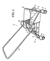
- eine perspektivische Ansicht eines erfindungsgemäßen Reinigungswagens mit einem Eimer,
- Fig. 2:
- eine Seitenansicht des erfindungsgemäßen Reinigungswagens gemäß Fig. 1 mit einem Eimer,
- Fig. 3:
- eine Frontansicht des erfindungsgemäßen Reinigungswagens gemäß Fig. 1 mit einem Eimer,
- Fig. 4:
- eine Frontansicht eines erfindungsgemäßen Reinigungswagens ohne Eimer,
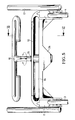
- Fig. 5:
- eine Frontansicht der Mittelstrebe eines erfindungsgemäßen Reinigungswagens in eingebautem Zustand,
- Fig. 6:
- eine teilweise geschnittene Seitenansicht der Mittelstrebe des erfindungsgemäßen Reinigungswagens mit eingesetztem Eimer,
- Fig. 7:
- eine Seitenansicht der Mittelstrebe des erfindungsgemäßen Reinigungswagens in eingebautem Zustand, und
- Fig. 8:
- einen senkrechten Schnitt durch die Mittelstrebe entlang der Linie VIII - VIII gemäß Fig. 7.
- Fig. 1:
- 1 shows a perspective view of a cleaning trolley according to the invention with a bucket,
- Fig. 2:
- 2 shows a side view of the cleaning trolley according to the invention according to FIG. 1 with a bucket,
- Fig. 3:
- 2 shows a front view of the cleaning trolley according to the invention according to FIG. 1 with a bucket,
- Fig. 4:
- 2 shows a front view of a cleaning trolley according to the invention without a bucket,
- Fig. 5:
- 2 shows a front view of the center strut of a cleaning trolley according to the invention in the installed state,
- Fig. 6:
- 3 shows a partially sectioned side view of the center strut of the cleaning trolley according to the invention with the bucket inserted,
- Fig. 7:
- a side view of the center strut of the cleaning trolley according to the invention in the installed state, and
- Fig. 8:
- a vertical section through the central strut along the line VIII - VIII of FIG. 7.
Der in Fig. 1 dargestellte Reinigungswagen 1 weist ein Grundgestell 2 auf, welches im wesentlichen aus zwei Seitenbügeln 3, 4 und zwei Querstreben 5, 6 gebildet ist, welche die gleichliegenden Enden der Seitenbügel 3, 4 miteinander verbinden. In die unteren Öffnungen der Seitenbügel 3, 4 sind Lenkrollen 7 eingesteckt, welche mit Stoßfängern 8 versehen sind. Die Querstreben 5, 6 sind über mehrere Längsstreben 9 miteinander verbunden. Im obersten Bereich in der Mitte der Seitenbügel 3, 4 ist eine brückenförmig ausgebildete Mittelstrebe 10 zur Verbindung der beiden Seitenbügel 3, 4 angeordnet. Die Mittelstrebe 10 ist mittels keilförmiger Spannelemente 11 mit den Seitenbügeln 3, 4 verspannt. Auf dem durch die Längsstreben 9 gebildeten Bodenrost steht ein Eimer 12, welcher mit seinem Rand 13 in eine (in Fig. 1 nicht sichtbare) Ausnehmung 14 der Mittelstrebe 10 eingreift. An der Mittelstrebe 10 ist in einer (ebenfalls nicht sichtbaren) Einstecköffnung 15 ein Pressenstativ 16 eingesetzt. Desweiteren ist an der Mittelstrebe 10 ein U-förmig ausgebildeter Handhabungsbügel 17 angebracht, welcher mit Führungsstiften 18 bzw. 19 in Bohrungen 20 bzw. Nuten 21 an der Mittelstrebe 10 bzw. an den Spannelementen 11 eingreift.The cleaning
In Fig. 2 ist zu erkennen, daß die Seitenbügel 3, 4 je zwei senkrecht verlaufende äußere Abschnitte 22 aufweisen, an welchen die Querstreben 5, 6 und die Lenkrollen 7 mit den Stoßfängern 8 angebracht sind. In der Mitte der Seitenbügel 3, 4 befindet sich ein Mittelabschnitt 23, welcher etwa horizontal verläuft und an welchem die Mittelstrebe 10 angebracht ist. Der Eimer 12 steht auf den Längsstreben 9 auf und liegt an einer Seite an der Mittelstrebe 10 und an der anderen Seite an der jeweiligen Querstrebe 5 an, welche zu diesem Zweck die Längsstreben 9 geringfügig überragen. Der Handhabungsbügel 17 ist um ca. 90° um seine unten in der Mitte der Mittelstrebe 10 befindliche Drehachse verschwenkbar und wird mit Führungsstiften 19 in den an den Spannelementen 11 vorgesehenen Nuten 21 geführt.In Fig. 2 it can be seen that the
Wie in Fig. 3 zu sehen ist, ist die Mittelstrebe 10 in Höhe des vorspringenden Randes 13 des Eimers 12 mit Ausnehungen 14 versehen, in welche der Rand 13 des Eimers 12 eingreift.As can be seen in FIG. 3, the
In Fig. 4 ist die Ausnehmung 14 in voller Länge zu erkennen. An der Unterseite der Mittelstrebe 10 ist eine Vorwölbung 24 vorgesehen, in welche sich die Einstecköffnung 15 für das Pressenstativ 16 erstreckt.The
Noch deutlicher ist die Ausgestaltung der Mittelstrebe 10 in Fig. 5 dargestellt. Die Spannelemente 11 sind oberhalb der Seitenbügel 3, 4 in Längsrichtung formschlüssig in die Mittelstrebe 10 eingesetzt. Das Pressenstativ 16 ist in der Einstecköffnung 15 drehbar gelagert und kann senkrecht nach oben aus der Einstecköffnung 15 herausgezogen werden.The configuration of the
In Fig. 6 ist zu erkennen, wie der vorspringende Rand 13 des Eimers 12 von der Seite her in die Ausnehmung 14 der Mittelstrebe 10 einsetzbar ist. Die Oberseite der Mittelstrebe 10 weist in Richtung der Eimer 12 hin abfallende Abschrägungen 25 auf, wobei die Vorder- und Hinterkanten 26, 27 der Mittelstrebe 10 jeweils bis über den Innenraum der Eimer 12 vorstehen. In den senkrechten Seitenabschnitten der Mittelstrebe 10 sind zylinderförmige Führungsbuchsen 28 mit Bohrungen 20 für die Anlenkung des Handhabungsbügels 17 vorgesehen.6 shows how the projecting
In Fig. 7 ist die Anbringung des Handhabungsbügels 17 an der Mittelstrebe 10 dargestellt. Die unteren Führungstifte 18 des Handhabungsbügels 17 sind in den Bohrungen 20 der Mittelstrebe 10 drehbar gelagert, während die oberen Führungsstifte 19 des Handhabungsbügels 17 in den kreissegmentförmig ausgebildeten Nuten 21 der Spannelemente 11 geführt sind.In Fig. 7 the attachment of the
Wie in Fig. 8 zu sehen ist, sind die Bohrungen 20 zur Aufnahme der unteren Führungsstifte 18 des Handhabungsbügels 17 in in die Mittelstrebe 10 eingesetzten Führungsbuchsen 28 vorgesehen.As can be seen in FIG. 8, the
Zur Montage des Reinigungswagens 1 werden zunächst die Längsstreben 9 in die Querstreben 5, 6 eingesteckt, um einen Rost zu bilden. Anschließend werden die Seitenbügel 3, 4 an die Mittelstrebe 10 mit Hilfe der Spannelemente 11 befestigt. Dann werden die Seitenbügel 3, 4 mit ihren senkrechten äußeren Abschnitten 22 durch die ebenfalls senkrecht verlaufenden Bohrungen in den Querstreben 5, 6 hindurchgeführt und mit den Stoßfängern 8 und den Lenkrollen 7 versehen. Nun wird der Handhabungsbügel 17 durch leichtes Auseinanderspreizen seiner beiden Seitenschenkel an der Mittelstrebe 10 befestigt, indem die Führungsstifte 18 in die Bohrungen 20 und die Führungsstifte 19 in die Nuten 21 eingesetzt werden. Zum Schluß wird das Pressenstativ 16 senkrecht von oben in die Einstecköffnung 15 der Mittelstrebe 10 eingesetzt, so daß die Drehbarkeit um seine vertikale Achse gewährleistet wird.To assemble the
Zur Demontage des Reinigungswagens 1 ist entsprechend in umgekehrter Reihenfolge vorzugehen.To dismantle the
- 11
- ReinigungswagenCleaning trolley
- 22nd
- GrundgestellBase frame
- 33rd
- SeitenbügelSide bracket
- 44th
- SeitenbügelSide bracket
- 55
- QuerstrebeCross strut
- 66
- QuerstrebeCross strut
- 77
- LenkrollenSwivel castors
- 88th
- StoßfängerBumpers
- 99
- LängsstrebenLongitudinal struts
- 1010th
- MittelstrebeMiddle strut
- 1111
- SpannelementeClamping elements
- 1212
- Eimerbucket
- 1313
- Randedge
- 1414
- AusnehmungenRecesses
- 1515
- EinstecköffnungInsertion opening
- 1616
- PressenstativPress stand
- 1717th
- HandhabungsbügelHandle
- 1818th
- FührungsstifteGuide pins
- 1919th
- FührungsstifteGuide pins
- 2020th
- BohrungenHoles
- 2121
- NutenGrooves
- 2222
- äußere Abschnitteouter sections
- 2323
- MittelabschnitteMiddle sections
- 2424th
- VorwölbungBulge
- 2525th
- AbschrägungenBevels
- 2626
- VorderkanteLeading edge
- 2727th
- HinterkanteTrailing edge
- 2828
- FührungsbuchsenGuide bushings
Claims (13)
Priority Applications (1)
| Application Number | Priority Date | Filing Date | Title |
|---|---|---|---|
| AT91103798T ATE91866T1 (en) | 1990-04-14 | 1991-03-13 | CLEANING TROLLEY. |
Applications Claiming Priority (2)
| Application Number | Priority Date | Filing Date | Title |
|---|---|---|---|
| DE9004319U DE9004319U1 (en) | 1990-04-14 | 1990-04-14 | |
| DE9004319U | 1990-04-14 |
Publications (2)
| Publication Number | Publication Date |
|---|---|
| EP0452674A1 true EP0452674A1 (en) | 1991-10-23 |
| EP0452674B1 EP0452674B1 (en) | 1993-07-28 |
Family
ID=6852918
Family Applications (1)
| Application Number | Title | Priority Date | Filing Date |
|---|---|---|---|
| EP91103798A Expired - Lifetime EP0452674B1 (en) | 1990-04-14 | 1991-03-13 | Cleaning trolley |
Country Status (3)
| Country | Link |
|---|---|
| EP (1) | EP0452674B1 (en) |
| AT (1) | ATE91866T1 (en) |
| DE (2) | DE9004319U1 (en) |
Cited By (1)
| Publication number | Priority date | Publication date | Assignee | Title |
|---|---|---|---|---|
| GB2388577A (en) * | 2002-04-25 | 2003-11-19 | Numatic Int Ltd | Janitorial trolley |
Families Citing this family (3)
| Publication number | Priority date | Publication date | Assignee | Title |
|---|---|---|---|---|
| DE9206733U1 (en) * | 1992-05-19 | 1992-07-30 | Vermop Salmon Gmbh, 6980 Wertheim, De | |
| US9980623B2 (en) | 2008-11-05 | 2018-05-29 | Ecolab Usa Inc. | Cleaning trolley |
| DE102013011631A1 (en) * | 2013-07-12 | 2015-01-15 | Carl Freudenberg Kg | cleaning trolley |
Citations (3)
| Publication number | Priority date | Publication date | Assignee | Title |
|---|---|---|---|---|
| DE2741836A1 (en) * | 1977-09-16 | 1979-03-29 | Floordress Reinigungsgeraete | Mobile office cleaning machine with bucket and press - has slotted ends of U=shaped handle for safe fastening with no danger of injury |
| DE3037442A1 (en) * | 1980-10-03 | 1982-05-13 | Rheinwerk Meisenburg & Ahleff GmbH, 4000 Düsseldorf | Wheeled laundry bag stand - has base with rotatable wheel mountings secured in lower ends of tubular posts holding bag retaining rings |
| DE8509181U1 (en) * | 1985-03-27 | 1985-05-09 | NWG Nord-West-Gebäudereinigung GmbH & Co KG, 4100 Duisburg | Equipment trolleys for cleaning purposes |
-
1990
- 1990-04-14 DE DE9004319U patent/DE9004319U1/de not_active Expired - Lifetime
-
1991
- 1991-03-13 AT AT91103798T patent/ATE91866T1/en not_active IP Right Cessation
- 1991-03-13 EP EP91103798A patent/EP0452674B1/en not_active Expired - Lifetime
- 1991-03-13 DE DE9191103798T patent/DE59100218D1/en not_active Expired - Fee Related
Patent Citations (3)
| Publication number | Priority date | Publication date | Assignee | Title |
|---|---|---|---|---|
| DE2741836A1 (en) * | 1977-09-16 | 1979-03-29 | Floordress Reinigungsgeraete | Mobile office cleaning machine with bucket and press - has slotted ends of U=shaped handle for safe fastening with no danger of injury |
| DE3037442A1 (en) * | 1980-10-03 | 1982-05-13 | Rheinwerk Meisenburg & Ahleff GmbH, 4000 Düsseldorf | Wheeled laundry bag stand - has base with rotatable wheel mountings secured in lower ends of tubular posts holding bag retaining rings |
| DE8509181U1 (en) * | 1985-03-27 | 1985-05-09 | NWG Nord-West-Gebäudereinigung GmbH & Co KG, 4100 Duisburg | Equipment trolleys for cleaning purposes |
Cited By (2)
| Publication number | Priority date | Publication date | Assignee | Title |
|---|---|---|---|---|
| GB2388577A (en) * | 2002-04-25 | 2003-11-19 | Numatic Int Ltd | Janitorial trolley |
| GB2388577B (en) * | 2002-04-25 | 2004-08-11 | Numatic Int Ltd | Improvements in and relating to janitorial trolleys |
Also Published As
| Publication number | Publication date |
|---|---|
| DE9004319U1 (en) | 1990-06-28 |
| EP0452674B1 (en) | 1993-07-28 |
| ATE91866T1 (en) | 1993-08-15 |
| DE59100218D1 (en) | 1993-09-02 |
Similar Documents
| Publication | Publication Date | Title |
|---|---|---|
| DE1116354B (en) | Collapsible bed frame | |
| DE2637235B2 (en) | Folding stroller | |
| DE2624478C2 (en) | Handle attachment to a harness | |
| EP0452674B1 (en) | Cleaning trolley | |
| EP0570900A1 (en) | Cleaning cart | |
| DE2023011C3 (en) | ||
| EP0457034A1 (en) | Folding laundry drying rack | |
| DE3021098C2 (en) | ||
| DE102017100974B4 (en) | Frame of a stroller | |
| DE4004536C2 (en) | ||
| DE8614831U1 (en) | Shopping venture | |
| DE2709018C2 (en) | Two-wheeled transport cart | |
| DE1997275U (en) | HUBLOADER. | |
| EP0571650B1 (en) | Knock-down table system | |
| DE2741836C2 (en) | Cleaning trolley | |
| DE1757150C2 (en) | Bottle basket for conveyor chain bottle washers | |
| DE2815415A1 (en) | TRANSPORT ROLLERS, IN PARTICULAR SHOPPING ROLLERS | |
| DE2055798A1 (en) | Hand sweeper | |
| DE7617050U1 (en) | DISMOUNTABLE CABINET | |
| DE2747153C2 (en) | Floating frames and / or brake carriers for disc brakes | |
| DE102005020057B3 (en) | Trolley structure, has checking units provided to peripheral edge of fan-shaped unit to insert into troughs, and active gear made and integrated to outer side of pivoting holder when active gear meshes with driven gear | |
| DE3008507C2 (en) | ||
| DE202006003121U1 (en) | Foldable stand for table assembly e.g. decoration table, has two tilting legs, where shanks are connected together by connecting strut with hinged point, and pivoted in U-profile part and other ends are connected with U-profile part | |
| DE1429746C (en) | Hanger, especially for towels or the like | |
| DE7626532U1 (en) | SHOPPING CART WITH FOLDING SHELF |
Legal Events
| Date | Code | Title | Description |
|---|---|---|---|
| PUAI | Public reference made under article 153(3) epc to a published international application that has entered the european phase |
Free format text: ORIGINAL CODE: 0009012 |
|
| AK | Designated contracting states |
Kind code of ref document: A1 Designated state(s): AT BE CH DE DK ES FR GB GR IT LI LU NL SE |
|
| 17P | Request for examination filed |
Effective date: 19920123 |
|
| 17Q | First examination report despatched |
Effective date: 19930113 |
|
| GRAA | (expected) grant |
Free format text: ORIGINAL CODE: 0009210 |
|
| AK | Designated contracting states |
Kind code of ref document: B1 Designated state(s): AT BE CH DE DK ES FR GB GR IT LI LU NL SE |
|
| PG25 | Lapsed in a contracting state [announced via postgrant information from national office to epo] |
Ref country code: IT Free format text: LAPSE BECAUSE OF FAILURE TO SUBMIT A TRANSLATION OF THE DESCRIPTION OR TO PAY THE FEE WITHIN THE PRE;WARNING: LAPSES OF ITALIAN PATENTS WITH EFFECTIVE DATE BEFORE 2007 MAY HAVE OCCURRED AT ANY TIME BEFORE 2007. THE CORRECT EFFECTIVE DATE MAY BE DIFFERENT FROM THE ONE RECORDED.SCRIBED TIME-LIMIT Effective date: 19930728 Ref country code: ES Free format text: THE PATENT HAS BEEN ANNULLED BY A DECISION OF A NATIONAL AUTHORITY Effective date: 19930728 Ref country code: NL Effective date: 19930728 Ref country code: GB Effective date: 19930728 Ref country code: SE Effective date: 19930728 Ref country code: FR Effective date: 19930728 Ref country code: GR Free format text: LAPSE BECAUSE OF FAILURE TO SUBMIT A TRANSLATION OF THE DESCRIPTION OR TO PAY THE FEE WITHIN THE PRESCRIBED TIME-LIMIT Effective date: 19930728 Ref country code: DK Effective date: 19930728 |
|
| REF | Corresponds to: |
Ref document number: 91866 Country of ref document: AT Date of ref document: 19930815 Kind code of ref document: T |
|
| REF | Corresponds to: |
Ref document number: 59100218 Country of ref document: DE Date of ref document: 19930902 |
|
| EN | Fr: translation not filed | ||
| NLV1 | Nl: lapsed or annulled due to failure to fulfill the requirements of art. 29p and 29m of the patents act | ||
| GBV | Gb: ep patent (uk) treated as always having been void in accordance with gb section 77(7)/1977 [no translation filed] |
Effective date: 19930728 |
|
| PG25 | Lapsed in a contracting state [announced via postgrant information from national office to epo] |
Ref country code: AT Effective date: 19940313 |
|
| PG25 | Lapsed in a contracting state [announced via postgrant information from national office to epo] |
Ref country code: CH Effective date: 19940331 Ref country code: LI Effective date: 19940331 Ref country code: LU Free format text: LAPSE BECAUSE OF NON-PAYMENT OF DUE FEES Effective date: 19940331 Ref country code: BE Effective date: 19940331 |
|
| PLBE | No opposition filed within time limit |
Free format text: ORIGINAL CODE: 0009261 |
|
| STAA | Information on the status of an ep patent application or granted ep patent |
Free format text: STATUS: NO OPPOSITION FILED WITHIN TIME LIMIT |
|
| 26N | No opposition filed | ||
| REG | Reference to a national code |
Ref country code: CH Ref legal event code: PL |
|
| PG25 | Lapsed in a contracting state [announced via postgrant information from national office to epo] |
Ref country code: DE Effective date: 19941201 |
|
| BERE | Be: lapsed |
Owner name: VERMOP SALMON G.M.B.H. Effective date: 19941031 |