EP0452603A1 - Einrichtung zum Schliessen von unter inneren Ueberdruck gesetzten Behältern - Google Patents
Einrichtung zum Schliessen von unter inneren Ueberdruck gesetzten Behältern Download PDFInfo
- Publication number
- EP0452603A1 EP0452603A1 EP90500070A EP90500070A EP0452603A1 EP 0452603 A1 EP0452603 A1 EP 0452603A1 EP 90500070 A EP90500070 A EP 90500070A EP 90500070 A EP90500070 A EP 90500070A EP 0452603 A1 EP0452603 A1 EP 0452603A1
- Authority
- EP
- European Patent Office
- Prior art keywords
- ring
- cover
- closing
- vessel
- upper cover
- Prior art date
- Legal status (The legal status is an assumption and is not a legal conclusion. Google has not performed a legal analysis and makes no representation as to the accuracy of the status listed.)
- Withdrawn
Links
- 230000002093 peripheral effect Effects 0.000 claims abstract description 21
- 238000007789 sealing Methods 0.000 claims description 11
- XLYOFNOQVPJJNP-UHFFFAOYSA-N water Substances O XLYOFNOQVPJJNP-UHFFFAOYSA-N 0.000 abstract description 6
- 239000004576 sand Substances 0.000 abstract description 5
- 230000002787 reinforcement Effects 0.000 description 2
- 230000002950 deficient Effects 0.000 description 1
- 230000000694 effects Effects 0.000 description 1
- 239000003337 fertilizer Substances 0.000 description 1
- 238000001914 filtration Methods 0.000 description 1
- 239000003365 glass fiber Substances 0.000 description 1
- 230000001788 irregular Effects 0.000 description 1
- 230000002262 irrigation Effects 0.000 description 1
- 238000003973 irrigation Methods 0.000 description 1
- 238000004519 manufacturing process Methods 0.000 description 1
- 239000000463 material Substances 0.000 description 1
- 238000000034 method Methods 0.000 description 1
- 229920000728 polyester Polymers 0.000 description 1
- 238000000926 separation method Methods 0.000 description 1
- 238000005507 spraying Methods 0.000 description 1
- 229910001220 stainless steel Inorganic materials 0.000 description 1
- 239000010935 stainless steel Substances 0.000 description 1
- 230000009182 swimming Effects 0.000 description 1
Images


Classifications
-
- B—PERFORMING OPERATIONS; TRANSPORTING
- B01—PHYSICAL OR CHEMICAL PROCESSES OR APPARATUS IN GENERAL
- B01J—CHEMICAL OR PHYSICAL PROCESSES, e.g. CATALYSIS OR COLLOID CHEMISTRY; THEIR RELEVANT APPARATUS
- B01J3/00—Processes of utilising sub-atmospheric or super-atmospheric pressure to effect chemical or physical change of matter; Apparatus therefor
- B01J3/03—Pressure vessels, or vacuum vessels, having closure members or seals specially adapted therefor
-
- B—PERFORMING OPERATIONS; TRANSPORTING
- B01—PHYSICAL OR CHEMICAL PROCESSES OR APPARATUS IN GENERAL
- B01D—SEPARATION
- B01D35/00—Filtering devices having features not specifically covered by groups B01D24/00 - B01D33/00, or for applications not specifically covered by groups B01D24/00 - B01D33/00; Auxiliary devices for filtration; Filter housing constructions
- B01D35/30—Filter housing constructions
-
- B—PERFORMING OPERATIONS; TRANSPORTING
- B01—PHYSICAL OR CHEMICAL PROCESSES OR APPARATUS IN GENERAL
- B01D—SEPARATION
- B01D2201/00—Details relating to filtering apparatus
- B01D2201/30—Filter housing constructions
- B01D2201/301—Details of removable closures, lids, caps, filter heads
-
- B—PERFORMING OPERATIONS; TRANSPORTING
- B01—PHYSICAL OR CHEMICAL PROCESSES OR APPARATUS IN GENERAL
- B01D—SEPARATION
- B01D2201/00—Details relating to filtering apparatus
- B01D2201/30—Filter housing constructions
- B01D2201/301—Details of removable closures, lids, caps, filter heads
- B01D2201/304—Seals or gaskets
Definitions
- This invention relates to a device for closing pressurised vessels, particularly for vessels for sand filters for pressurised water, of the type used in swimming pools, in water purifiers, in certain types of irrigation, etc., as well as in the administration of products such as fertilizers, plaguicides or others, by dripping or spraying.
- the said vessels are normally made from glass fibre reinforced polyester or stainless steel and the lids are domed and are attached conventionally thereto by a plurality of screws or nuts, with a sealing joint, whereby both the assembly and subsequent operation of the lid are laborious and time consuming.
- Another known embodiment consists of using a domed lid with a peripheral flange bearing against a further external flange of the vessel mouth, with a resilient joint therebetween housed in respective grooves of said flanges, the lid being held in place by two grooved half rings hingedly connected together at one end and having a closing lever at the other.
- This process has the drawback that with the water pressure acting directly on the domed portion of the lid, this is opposed to the sealing function of the joint, thereby causing a deficient sealing.
- the object of the invention is a device characterised in that it comprises a lid constituted by an upper cover forming a peripheral rim engagable around the vessel mouth on the outside thereof, a lower cover axially slidingly associated with the first cover, an external rotating control provided with a screw arrangement capable of raising and lowering the lower cover through the upper cover and an O-ring seal located between respective peripheral surfaces diverging from the contour of both covers defining a throat and which in the closing operation is compressed between said surfaces and expands to reach the inner edge of the vessel mouth.
- the upper and lower covers are sliding assembled together along respective peripheral skirts, such that the skirt of the upper cover comprises a lower double walled fold surrounding the skirt of the lower cover, which fold is closed at the bottom end by external and internal sloping surfaces, while the said skirt of the lower cover forms a protruding sloping surface, terminating in a protruding rim, engaged by the inner sloping surface of the upper cover, forming between both members a throat to house the O-ring, in combination with the lower edge of the vessel mouth.
- the vessel mouth is provided with an inner rim having the form of an inwardly folded lip.
- This ring has a general inverted T-shaped section and is fixedly attached by the outer surface thereof to the periphery of the charge mouth, while the peripheral rim of the lid seats against the upper edge thereof and the sealing gasket is pressed against the lower inner edge of said ring.
- the sealing gasket will be formed by an annular strip provided on the inner surface thereof with a peripheral expansion spring ensuring a tight seal and preventing the elastic recoil of the gasket.
- This gasket has its upper and lower edges housed in respective slots of the facing peripheries of the upper cover and of the lower cover that form the lid.
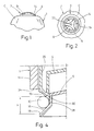
- Figures 1 and 2 show the upper portion of a vessel 1 for a sand filter, comprising a casing c which in the upper portion thereof forms the corresponding charge mouth 2 to which a lid 3 of the device of the invention is applied.
- the said lid mounted in the charge mouth of the vessel 1, comprises an upper cover 4 and a lower cover 5 axially associated together by an axial screw 6 fixedly attached to the lower cover and which passes through the orifice 7 to the upper cover.
- a nut 8 fixedly attached to an external rotating control 9 is threaded on the screw and a resilient O-ring seal 10 is disposed between the peripheries of said two covers.
- Figure 3 shows the relative positions of the members forming the lid which engages on the casing c of the vessel 1 which, in this case, forms a mouth having an inwardly folded rim 11.
- the upper cover 4 is slightly tapering and is provided with reinforcement formed by internal annular ribs 24 and radial ribs 25, plus a recessed fold 20 formed by two mutually parallel walls joined together at the bottom end thereof and a bent terminal rim 14 which engages the upper portion of the vessel 1.
- the lower cover 5 is also slightly tapering and is provided with annular ribs 26 and radial ribs 27 on the inner surface thereof and forms a peripheral skirt 28.
- the parallel walls of the fold 20 are attached together not only at the lower end, but also by radial walls 29 which also form a reinforcement.
- Figure 4 shows the assembly zone of the upper and lower covers 4 and 5, including the O-ring seal 10, such that the peripheral fold of the upper cover 4 terminates in internal 30 and external 19 sloping surfaces while the skirt 28 of the lower cover 5 forms a protruding sloping surface 16 terminating in an also protruding horizontal peripheral rim 18.
- the screw 6 may have its head attached to the upper control 9 and the lower portion may be engaged in a nut mounted in the lower cover 5, in which case it will be necessary to provide at the lower end of the screw a member preventing any possible separation of the nut caused by excessive rotation of said upper control 9.
- the upper cover 4 and the lower cover 5 are seen to be separated in the left hand side of Figure 3, from which position, by operating the rotating control 9, the closed position shown in the other half of the figure is attained.
- the sloping surface 16 of the lower cover 5 bears against the inner sloping surface 30 of the upper cover 4, whereby the O-ring seal 10 is trapped, on the one hand, between the surface 16 and the peripheral rim 18 of the lower cover 5 and, on the other hand, between the outer sloping surface 19 of the upper cover 4 and the lower edge 34 of the inwardly folded rim of the vessel 1.
- the height of the fold 20 of the upper cover 4 will be modified, without modififying the height H between the covers 4 and 5.
- the O-ring seal 10 will engage the lower surface of the mouth of the vessel 1.
- the peripheral rim 14 of the upper cover engages a shoulder 15 of the upper edge of the ring 12 and the O-ring seal 10 is pressed, by the sloping peripheral surface 16 of the lower cover, against the sloping surface 17 of the inner lower edge of the said ring.
- the O-ring seal 10 is pressed against the sloping surface 17, the sloping surface 16 terminated in the horizontal surface 18, and the sloping surface 19 formed on the lower fold 20 forming the upper cover 4.
- the seal will be formed by an elastic strip 10' (Figure 6) placed edge-on between the facing peripheries of the upper cover 4 and the lower cover 5 for which purpose these are provided with respective annular slots 21 and 22 where the upper and lower edges of said strip respectively engage.
- An annular coil spring 23 is housed on the inner surface of the strip and works by expansion, so that when the vessel is closed it holds the seal in its pressed position against the inner lower edge of the inwardly folded rim 11 of the vessel mouth, or the ring 12 fixedly attached to said mouth ( Figure 7).
Landscapes
- Chemical & Material Sciences (AREA)
- Chemical Kinetics & Catalysis (AREA)
- Organic Chemistry (AREA)
- Closures For Containers (AREA)
- Pressure Vessels And Lids Thereof (AREA)
Applications Claiming Priority (2)
| Application Number | Priority Date | Filing Date | Title |
|---|---|---|---|
| ES9001092A ES2024172A6 (es) | 1990-04-18 | 1990-04-18 | Dispositivo para tapar la boca de recipientes a presion. |
| ES9001092 | 1990-04-18 |
Publications (1)
| Publication Number | Publication Date |
|---|---|
| EP0452603A1 true EP0452603A1 (de) | 1991-10-23 |
Family
ID=8266912
Family Applications (1)
| Application Number | Title | Priority Date | Filing Date |
|---|---|---|---|
| EP90500070A Withdrawn EP0452603A1 (de) | 1990-04-18 | 1990-07-20 | Einrichtung zum Schliessen von unter inneren Ueberdruck gesetzten Behältern |
Country Status (3)
| Country | Link |
|---|---|
| EP (1) | EP0452603A1 (de) |
| ES (1) | ES2024172A6 (de) |
| PT (1) | PT94919A (de) |
Cited By (3)
| Publication number | Priority date | Publication date | Assignee | Title |
|---|---|---|---|---|
| US5850934A (en) * | 1993-12-30 | 1998-12-22 | Kumar; M. Lalith | Pressure vessel seal with self-energizing seal |
| WO2017048142A1 (en) | 2015-09-15 | 2017-03-23 | ENBIO TECHNOLOGY Sp.z o. o. | Closing unit of an autoclave process chamber |
| WO2017204666A1 (en) | 2016-05-21 | 2017-11-30 | Enbio Technology Sp. Z O.O. | Tank closing unit |
Citations (3)
| Publication number | Priority date | Publication date | Assignee | Title |
|---|---|---|---|---|
| DE386439C (de) * | 1921-04-02 | 1923-12-20 | Wilhelm Frankenbusch | Verschluss fuer Lager- und Versandgefaesse |
| CH249611A (de) * | 1946-06-13 | 1947-07-15 | Knecht Eugen | Verschluss an Gefässen, Leitungen usw. |
| US4659466A (en) * | 1985-03-01 | 1987-04-21 | Farr Company | Quick release cover assembly for a liquid filter housing |
-
1990
- 1990-04-18 ES ES9001092A patent/ES2024172A6/es not_active Expired - Lifetime
- 1990-07-20 EP EP90500070A patent/EP0452603A1/de not_active Withdrawn
- 1990-08-06 PT PT9491990A patent/PT94919A/pt not_active Application Discontinuation
Patent Citations (3)
| Publication number | Priority date | Publication date | Assignee | Title |
|---|---|---|---|---|
| DE386439C (de) * | 1921-04-02 | 1923-12-20 | Wilhelm Frankenbusch | Verschluss fuer Lager- und Versandgefaesse |
| CH249611A (de) * | 1946-06-13 | 1947-07-15 | Knecht Eugen | Verschluss an Gefässen, Leitungen usw. |
| US4659466A (en) * | 1985-03-01 | 1987-04-21 | Farr Company | Quick release cover assembly for a liquid filter housing |
Cited By (3)
| Publication number | Priority date | Publication date | Assignee | Title |
|---|---|---|---|---|
| US5850934A (en) * | 1993-12-30 | 1998-12-22 | Kumar; M. Lalith | Pressure vessel seal with self-energizing seal |
| WO2017048142A1 (en) | 2015-09-15 | 2017-03-23 | ENBIO TECHNOLOGY Sp.z o. o. | Closing unit of an autoclave process chamber |
| WO2017204666A1 (en) | 2016-05-21 | 2017-11-30 | Enbio Technology Sp. Z O.O. | Tank closing unit |
Also Published As
| Publication number | Publication date |
|---|---|
| ES2024172A6 (es) | 1992-02-16 |
| PT94919A (pt) | 1991-10-31 |
Similar Documents
| Publication | Publication Date | Title |
|---|---|---|
| US4015757A (en) | Rapid charging valve for a pressurized dispenser | |
| US4893645A (en) | Control valve with improved dual mode operation and flow adjustment | |
| US4855047A (en) | High pressure spin-on filter | |
| US3957640A (en) | Liquid filter | |
| US3724665A (en) | Filter unit | |
| US5445734A (en) | Water filter | |
| US4758256A (en) | Air filter with removable bridge assembly | |
| CA2130656C (en) | Filter screen and method of making same | |
| US3513977A (en) | Lint pot for swimming pool filter | |
| US3921910A (en) | Pop-up sprinkler with multiple-purpose one-piece seal | |
| JPS6038168B2 (ja) | 高強度ねじ込みフィルタ | |
| CN1083412A (zh) | 空气滤清器密封槽 | |
| CA1227781A (en) | Gate valve | |
| US4007857A (en) | Safeguard cap structure particularly for bottles | |
| US2800912A (en) | Mounting for pressure relief valve | |
| RU96108785A (ru) | Смеситель, имеющий шаровой клапан и верхнюю уплотнительную прокладку | |
| US5056759A (en) | Protected bellows for valve | |
| US4383620A (en) | Container and closure | |
| YU49157B (sh) | Posuda za kuvanje | |
| EP0452603A1 (de) | Einrichtung zum Schliessen von unter inneren Ueberdruck gesetzten Behältern | |
| US4344458A (en) | Accumulator device with improved bladder seal | |
| US2988170A (en) | Air cleaner and silencer | |
| IE47203B1 (en) | Cover for kitchen containers | |
| CA2123196A1 (en) | Fuel filter with drain/fill/sensor port | |
| US3118837A (en) | Filter |
Legal Events
| Date | Code | Title | Description |
|---|---|---|---|
| PUAI | Public reference made under article 153(3) epc to a published international application that has entered the european phase |
Free format text: ORIGINAL CODE: 0009012 |
|
| AK | Designated contracting states |
Kind code of ref document: A1 Designated state(s): DE FR GB GR IT |
|
| STAA | Information on the status of an ep patent application or granted ep patent |
Free format text: STATUS: THE APPLICATION IS DEEMED TO BE WITHDRAWN |
|
| 18D | Application deemed to be withdrawn |
Effective date: 19920424 |