EP0452552A2 - Film peeling method and apparatus for practicing same - Google Patents
Film peeling method and apparatus for practicing same Download PDFInfo
- Publication number
- EP0452552A2 EP0452552A2 EP90123703A EP90123703A EP0452552A2 EP 0452552 A2 EP0452552 A2 EP 0452552A2 EP 90123703 A EP90123703 A EP 90123703A EP 90123703 A EP90123703 A EP 90123703A EP 0452552 A2 EP0452552 A2 EP 0452552A2
- Authority
- EP
- European Patent Office
- Prior art keywords
- film
- base plate
- conveyance
- tightness
- peeling
- Prior art date
- Legal status (The legal status is an assumption and is not a legal conclusion. Google has not performed a legal analysis and makes no representation as to the accuracy of the status listed.)
- Granted
Links
Images


Classifications
-
- H—ELECTRICITY
- H05—ELECTRIC TECHNIQUES NOT OTHERWISE PROVIDED FOR
- H05K—PRINTED CIRCUITS; CASINGS OR CONSTRUCTIONAL DETAILS OF ELECTRIC APPARATUS; MANUFACTURE OF ASSEMBLAGES OF ELECTRICAL COMPONENTS
- H05K3/00—Apparatus or processes for manufacturing printed circuits
- H05K3/0073—Masks not provided for in groups H05K3/02 - H05K3/46, e.g. for photomechanical production of patterned surfaces
- H05K3/0079—Masks not provided for in groups H05K3/02 - H05K3/46, e.g. for photomechanical production of patterned surfaces characterised by the method of application or removal of the mask
-
- B—PERFORMING OPERATIONS; TRANSPORTING
- B29—WORKING OF PLASTICS; WORKING OF SUBSTANCES IN A PLASTIC STATE IN GENERAL
- B29C—SHAPING OR JOINING OF PLASTICS; SHAPING OF MATERIAL IN A PLASTIC STATE, NOT OTHERWISE PROVIDED FOR; AFTER-TREATMENT OF THE SHAPED PRODUCTS, e.g. REPAIRING
- B29C63/00—Lining or sheathing, i.e. applying preformed layers or sheathings of plastics; Apparatus therefor
- B29C63/0004—Component parts, details or accessories; Auxiliary operations
- B29C63/0013—Removing old coatings
-
- G—PHYSICS
- G03—PHOTOGRAPHY; CINEMATOGRAPHY; ANALOGOUS TECHNIQUES USING WAVES OTHER THAN OPTICAL WAVES; ELECTROGRAPHY; HOLOGRAPHY
- G03F—PHOTOMECHANICAL PRODUCTION OF TEXTURED OR PATTERNED SURFACES, e.g. FOR PRINTING, FOR PROCESSING OF SEMICONDUCTOR DEVICES; MATERIALS THEREFOR; ORIGINALS THEREFOR; APPARATUS SPECIALLY ADAPTED THEREFOR
- G03F7/00—Photomechanical, e.g. photolithographic, production of textured or patterned surfaces, e.g. printing surfaces; Materials therefor, e.g. comprising photoresists; Apparatus specially adapted therefor
- G03F7/16—Coating processes; Apparatus therefor
-
- Y—GENERAL TAGGING OF NEW TECHNOLOGICAL DEVELOPMENTS; GENERAL TAGGING OF CROSS-SECTIONAL TECHNOLOGIES SPANNING OVER SEVERAL SECTIONS OF THE IPC; TECHNICAL SUBJECTS COVERED BY FORMER USPC CROSS-REFERENCE ART COLLECTIONS [XRACs] AND DIGESTS
- Y10—TECHNICAL SUBJECTS COVERED BY FORMER USPC
- Y10T—TECHNICAL SUBJECTS COVERED BY FORMER US CLASSIFICATION
- Y10T156/00—Adhesive bonding and miscellaneous chemical manufacture
- Y10T156/11—Methods of delaminating, per se; i.e., separating at bonding face
- Y10T156/1105—Delaminating process responsive to feed or shape at delamination
-
- Y—GENERAL TAGGING OF NEW TECHNOLOGICAL DEVELOPMENTS; GENERAL TAGGING OF CROSS-SECTIONAL TECHNOLOGIES SPANNING OVER SEVERAL SECTIONS OF THE IPC; TECHNICAL SUBJECTS COVERED BY FORMER USPC CROSS-REFERENCE ART COLLECTIONS [XRACs] AND DIGESTS
- Y10—TECHNICAL SUBJECTS COVERED BY FORMER USPC
- Y10T—TECHNICAL SUBJECTS COVERED BY FORMER US CLASSIFICATION
- Y10T156/00—Adhesive bonding and miscellaneous chemical manufacture
- Y10T156/19—Delaminating means
- Y10T156/1906—Delaminating means responsive to feed or shape at delamination
Definitions
- the present invention relates to an art in which a film stuck to a plate is peeled therefrom and discharged.
- a printed circuit board for an electronic machine such as a computer
- wirings of copper or the like are provided in a prescribed pattern on one or both sides of an electrically insulating plate.
- the printed circuit board is manufactured as described from now on.
- a stratified body consisting of a photosensitive resin layer, which is a photoresist layer, and a cover film, which is made of a light-transmissible resin and protects the photosensitive resin layer, is first stuck, under heat and pressure, to an electroconductive layer provided on the plate.
- a wiring pattern film is then overlaid on the stratified body.
- the photosensitive resin layer is thereafter exposed to light through the wiring pattern film and the cover film for a prescribed time.
- the exposed photosensitive resin layer is developed so that an etching mask pattern is formed.
- the unnecessary portions of the electroconductive layer are thereafter removed by etching.
- the remaining portions of the photosensitive resin layer are then removed.
- the printed circuit board having the wirings in the prescribed pattern is thus manufactured.
- An automatic film peeling apparatus which is a machine for automatically peeling such a film from such a layer, was developed as disclosed in the Japanese Patent Application (OPI) No. 271356/89 (the term "OPI” as used herein means an "unexamined published application”) corresponding to USSN 342,827.
- the apparatus peels a part of the film stuck to a plate, peels the other parts of the film starting with the border of the latter part on the former, and then discharges the peeled film.
- the apparatus includes a first film conveyance means by which the film having the former part peeled from the plate is conveyed upward over the surface of the plate while the film is pinched by a belt conveyor so that the film is peeled from the plate, and a second film conveyance means by which air is blown to the film conveyed by the first film conveyance means, so that the film is conveyed to a peeled film container.
- the plate is temporarily stopped when the tightness of the contact between the former part of the film and the plate is reduced or the part is peeled from the plate. For that reason, the efficiency of the peeling of the film from the plate is low. This is a problem.
- the present invention was made in order to solve the above-mentioned problem.
- the first object of the present invention to provide an art in which the tightness of the contact of films with a base plate is reduced at the leading edges of the films without stopping the conveyance of the base plate while peeling them from the base plate, to enhance the efficiency of the peeling of the film.
- the films stuck to the base plate are peeled therefrom.
- the method has a major feature that the base plate stuck with the films is conveyed to a position wherein the films are peeled at the leading edges thereof from the base plate; the tightness of the contact of the films with the base plate is reduced at the leading edge of the films while the difference between the speed of the conveyance of the base plate and that of the movement of a film contact tightness reduction means is decreased and the conveyance of the base plate is not stopped; and a fluid is blown into the gaps between the base plate and the tightness-reduced films at the leading edges thereof to discharge the films while peeling the tightness-reduced films from the base plate.
- the base plates stuck with the films is conveyed to the position wherein the films are peeled at the leading edges thereof from the base plate.
- the tightness of the contact of the films with the base plate is reduced at the leading edges of the films without stopping the conveyance of the base plate.
- the fluid is blown into the gaps between the base plate and the tightness-reduced films at the leading edges thereof to discharge the films while peeling the tightness-reduced films from the base plate. As a result, the efficiency of the peeling of the films is enhanced.
- the conveyance of the baseplate is temporarily stopped in a prescribed position on a base plate conveyance means so that the obliqueness of the base plate is corrected and the base plate is centered before the tightness of the contact of the films with the base plate is reduced at the leading edges thereof, the base plate is accurately positioned so that the tightness of the contact of the films with the base plate can be smoothly reduced at the leading edges of the films.
- the speed of the conveyance of the base plate is decreased when the base plate is conveyed to a prescribed position upstream of the position wherein the films are peeled from the base plate at the leading edges of the films and the tightness of the contact of the films with the base plate is reduced at the leading edges of the films, the reduction can smoothly performed through relative simple constitution.
- the second object can thus be attained.
- the base plate is rapidly conveyed at the time of the discharge of the films so as to enhance the efficiency of the peeling of the films.
- the films are smoothly peeled by blowing the fluid thereto.
- the cone-shaped tip portions of film scratchers are vibrated in the axial directions thereof in contact with the surface of the film while extending downward obliquely to the direction of the conveyance of the base plate, to impart vibratory energy to the film to reduce the tightness of the contact thereof with the base plate at the leading edge of the film, the reduction is surely performed without stopping the conveyance of the base plate.
- the film scratchers are moved by a prescribed length in the direction of the conveyance of the base plate relative thereto while being in contact with the surface of the film, the reduction is more surely performed.
- the base plate is forcibly conveyed in reducing the tightness of the contact of the films with the base plate at the leading edges of the films, the base plate can be surely conveyed without stopping the conveyance thereof, regardless of the operative forces of the film scratchers and so forth.
- the upper pinch roller is forcibly rotated by the lower roller, it is possible to positively feed the baes plate regardless of a change of the thickness of the base plate.
- fluid blowoff nozzle units which have fluid ejection holes oriented to the film scratcher contact portions of the gaps between the base plate and the films and have fluid ejection holes oriented to the leading edges of the films near the film scratcher contact portions are provided so that the nozzle units are preferably located between the conveyance passage for the base plate and the film scratchers near the scratchers, the films can be surely peeled from the base plate by blowing the fluid to the films.
- leading edge portions of the films which are peeled from the base plate by blowing the fluid to the films, are caused to cling to the fluid guide plates by the pressure of the fluid, the peeling of the films and the introduction of them into discharge passages through the blowing of the fluid can be smoothly performed.
- blowing the fluid to the tightness-reduced portions of the films to peel them from the base plate is stopped when the films have arrived from the stage of the blowing of the fluid to the films at the stage of the discharge of the films along with the peeling thereof, the blowing of the fluid can be precisely terminated.
- the films can be rapidly peeled.
- peeled film guides shaped as rods and made of an electroconductive substance and/or an ion generator is used, static electricity can be eliminated from the films in discharge passages for the peeled films to smoothly discharge the films.
- the films peeled from both the side of the base plate are discharged into a common film container, it is easy to accommodate the peeled films.
- the steps of the method are subjected to sequential control through the use of the relays and timers of a programmable logic sequential controller, the steps can be automatically controlled.
- a film peeling apparatus provided in accordance with the present invention to attain the second object is characterized by including a base plate conveyance means for conveying the base plate stuck with the films; a base plate centering start position sensor for detecting that the base plate is conveyed forward on the conveyance means and reaches a prescribed position upstream of the position of peeling of the films from the base plate; a base plate centering unit which is put into action on the base of the output from the centering start position sensor so as to move the center of the width of the base plate to the center line of the conveyance means; a base plate slowing means for decreasing the speed of the conveyance of the base plate at the end of the action of the centering unit; film edge sensors for detecting the leading edges of the films stuck to the base plate; a film contact tightness reduction means which is put into action on the basis of the outputs from the film edge sensors so as to reduce the tightness of the contact of the films with the base plate at the leading edges of the films without stopping the conveyance of the base plate; a fluid blowing means for blow
- the base plate conveyance means, the base plate centering start position sensor, the base plate centering unit, the base plate slowing means, the film edge sensors, the film contact tightness reduction means, the fluid blowing means, the film peeling sensors and the film pinch means are provided so that the base plates stuck with the films is conveyed to the position of the peeling of the leading edge portions for the films, the tightness of the contact of the films with the base plate is reduced at the leading edges of the films without stopping the conveyance of the base plate, and the films are discharged while being peeled after the reduction in the tightness of the contact. For that reason, the films can be automatically and efficiently peeled from the base plate.
- a base plate insertion sensor for detecting the insertion of the base plate into the inlet portion of the base plate conveyance means in order to start the conveyance of the base plate is provided in the film peeling apparatus, the conveyance can be automatically started.
- the conveyance can be automatically stopped.
- guide members and guide rollers are provided in the apparatus so as to guide the base plate to prevent it from sagging, even if the thickness of the base plate is small, the films can be smoothly peeled from the base plate regardless of the thickness thereof.
- peeled film guide members for guiding the peeled films having passed through the film pinch means made of film catch belts, for example, and fluid ducts for discharging the films guided by the guide members are provided in the apparatus, the peeled films can be smoothly discharged.
- a return sensor for detecting the termination of the action of the base plate centering unit is provided in the apparatus and is a magnetic sensor which reacts to the position of an actuator for driving the centering unit, the termination can be detected without contact with the centering unit.
- the film edge sensors are of electrostatic capacity reaction type, the edges of the films can be precisely detected in terms of the difference in electrostatic capacity.
- the films stuck to the base plate are peeled therefrom.
- the method has a major feature that the base plate stuck with the films is conveyed to a position wherein the films are peeled from the base plate at the leading edges of the films; the tightness of the contact of the films with the base plate is reduced at the leading edges of the films while a film contact tightness reduction mechanism is moved, for a prescribed time, at a speed synchronized with that of the conveyance of the base plate and the speed of the conveyance is substantially unchanged; and a fluid is blown into the gaps between the base plate and the tightness-reduced films at the leading edges thereof to discharge the films while peeling the tightness-reduced films.
- the base plate stuck with the films is conveyed to the position of the peeling of the films at the leading edges thereof, the tightness of the contact of the films with the base plate is reduced at the leading edges of the films while the film contact tightness reduction mechanism is moved at the speed synchronized with that of the conveyance of the base plate and the speed of the conveyance is substantially unchanged, and the fluid is blown into the gaps between the base plate and the tightness-reduced films at the leading edges thereof to discharge the films while peeling the tightness-reduced films. For that reason, the efficiency of the peeling of the films can be more enhanced.
- a film peeling apparatus provided in accordance with the present invention to attain the third object includes a base plate conveyance means having conveyance rollers; a base plate centering start position sensor; a base plate centering unit; a base plate leading edge sensor; a film contact tightness reduction means; a fluid blowing means; a support frame fitted with the tightness reduction means and the fluid blowing means and movable in the direction of the conveyance of the base plate; a means for moving the support frame synchronously with the rotation of the conveyance rollers for a prescribed time so that the speed of the conveyance of the base plate is substantially unchanged during the reduction in the tightness of the contact of the films with the base plate; film peeling sensors; a film discharge means; and a sequential control means which operates on the basis of the output signals from the sensors.
- the base plate is conveyed to the position wherein the films are peeled from the base plate at the leading edges of the films.
- the tightness of the contact of the films with the base plate is reduced at the leading edges of the films while the support frame is moved at a speed synchoronized with that of the conveyance of the base plate and the speed of the conveyance is substantially unchanged.
- a fluid is blown in between the base plate and the leading edges of the tightness-reduced films to discharge the films while peeling the tightness-reduced films. As a result, the efficiency of the peeling of the films can be more enhanced.
- the base plate conveyance means has a base plate push conveyance roller and is provided with a mechanism which drives the roller on the bases of the output signal from the base plate leading edge sensor so as to push the base plate and stops the pushing thereof after a prescribed time, the base plate can be surely and synchronously conveyed even during the reduction of the tightness of the contact of the films with the base plate.
- the means for moving the support frame has a crank mechanism which is driven synchornously with the rotation of the base plate conveyance rollers, the support frame can be easily moved in the direction for the conveyance of the base plate.
- crank mechanism includes crank members coupled at one end of each thereof to the support frame and includes an one-way clutch means for synchronizing the movement of the crank members and the rotation of the base plate conveyance rollers with each other only while the tightness of the contact of the films with the base plate is reduced at the leading edges of the films, the movement of the support frame does not interfere with the rotation of the conveyance rollers.
- the base plate leading edge sensor is provided near the film edge sensors, the base plate can be surely detected even if the films are stuck to the whole surfaces of the base plate.
- Embodiments of the present invention are hereafter described in detail with reference to the drawings attached hereto.
- the embodiments are applied to a method of peeling a protective cover film from a base plate for a printed circuit and an apparatus for practicing the method.
- Equivalents shown in the drawings are denoted by the same reference symbols and not repeatedly described in detail, hereinafter.
- Fig. 1 is a perspective schematic view of the apparatus according to a first embodiment by which the protective cover film is peeled from the base plate.
- Fig. 2A is a detailed view of the pneumatic film conveyance box of the apparatus and the vicinity of the box.
- the base plate conveyance mechanism of the apparatus includes plate conveyance roller units 102 and 101 attached to the body 100 of the apparatus, in the plate advancing direction A as shown in Fig. 1.
- An air duct rest 103 is provided over the plate conveyance roller unit 102.
- One end of the air duct rest 103 is fixed to the body 100.
- An air duct 104 made of a transparent material is provided on the air duct rest 103.
- the left side (as viewed in the plate advancing direction A) of the air duct 104 is connected to a top opening of a peeled film discharge duct 105 having a large number of air pressure reduction holes 105A on the side thereof.
- Air passage holes 104D are provided in the right side of the air duct 104.
- the top and front side of the air duct 104 are integrated with each other to constitute a part of a cover 104A attached to the body 104C of the duct by hinges 104B so that the cover can be opened and closed.
- an ion-generator 110 for removing static electricity from the peeled film blower fans 109A and 109B and a film discharge air nozzle (not shown).
- the outlet of the peeled film discharge duct 105 is located over a peeled film container 106, which receives the peeled film.
- the container 106 includes a base 106A having a large number of air pressure reduction holes, a netted portion 106B, and casters 106C.
- a control panel 107 is provided on a side of the body 100 of the apparatus.
- a warning lamp 108 is provided on the top of the apparatus body 100.
- the film buoy-up members 3 of a film buoy-up unit such as a pneumatic vibrator type film scratcher
- the fluid blowoff nozzle members 4 of a fluid blowing unit are provided along a base plate conveyance passage A-A on the base plate conveyance mechanism.
- the base plate 1 for the printed circuit is made of an electric insulator coated with an electroconductive layer of copper or the like on one or both sides of the base plate.
- a stratified body consisting of a photosensitive resin layer, which is a photoresist layer, and the cover film, which is a protective film, is stuck, under heat and pressure, to the electroconductive layer of the plate 1 in advance.
- the plate 1 is brought to the film peeling apparatus after the photosensitive resin layer is exposed to light through a prescribed wiring pattern film overlaid on the stratified body.
- the plate 1 is conveyed by the drive rollers 2 of the plate conveyance roller units 101 and 102 in a direction A shown in Fig. 2A.
- a base plate push conveyance roller 2A which is a pinch roller, is provided so that a base plate 1 for a printed circuit board is prevented from being displaced out of centered state when the base plate passes on the roller and cover films are peeled from the base plate.
- the upper pinch roller 2A is depressed against the plate surface from above by a roller push plate 317 so that the plate may be positively fed by the rotation of the upper roller 2A.
- a roller push portion 317A of the roller push plate 317 has an inverted U-shape so as to permit the upper roller 2A movable downwardly.
- a lever 318 carries the roller push plate 317.
- the lever 318 has a U-shaped connection member receiving portion 318A which in turn engages a coupling member 319 fixed to a tip end of a rod of the push roller elevating/lowering pneumatic cylinder 321.
- the roller push plate support lever 318 is rotated about a pivot 318B, to thereby move the roller push plate 317 up and down. Since the air guide plate 5 is provided on the roller push plate 317, the vertical position of the air guide plate 5 is also changed in response to the vertical position change of the upper roller 2A (i.e., the roller push plate 317) in correspondence with the change of the thickness of the base plate 1. Accordingly, even if the thickness of the base plate 1 is changed, it is possible to automatically keep in a predetermined range (0.5-1.5 mm for example), suitable for keeping air flow and raising the film, a distance between the air guide plate 5 and the base plate top surface. It should be noted that the vertical position of the air guide plate 5 is manually adjustable in response to the thickness of the base plate 1.
- the above-mentioned upper pinch roller 2A is forcibly driven by a pair of gears 401 and 402 which are fixed to the ends, on the same side, of the lower drive roller 2 and the upper pinch roller 2A and engaged with each other with a large module ratio.
- the reason why the large module ratio gears are used is that, when the thickness of the base plate 1 is changed, the space between the pinch roller 2A and the drive roller 2 is also changed. In this manner, if the gears having the large module ratio, i.e., long teeth are used, even if the space between the engaged teeth is enlarged, since the engagement allowance is large, it is possible to responds to the change of the gear tooth space due to the change in thickness of the base plate.
- the base plate is positively delivered.
- the scratcher and the base plate may be moved relative to each other. Accordingly, it is possible to avoid a fear that the base plate would be drawn by the scratcher during the scratch operation. It is possible to loosen the film smoothly and positively.
- Fig. 3A is a view of a film contact tightness reduction mechanism seen oppositely to the direction of the conveyance of the base plate 1.
- Fig. 3B is a side view of the mechanism seen along an arrow L shown in Fig. 3A.
- Fig. 3C is a perspective view of the mechanism.
- Fig. 3D is a perspective view of a film edge detection mechanism.
- a film buoy-up unit at least one support member 10 for a film buoy-up member 3 is secured to each of buoy-up member support rotary shafts 9 provided over and under a base plate conveyance plane, as shown in Figs. 2A, 3A, 3B and 3C.
- a sliding block 13 is attached to the support member 10, and fitted on a guide rail 14 so that the block can be moved up and down.
- a buoy-up member support block 16 is secured to the guide rail 14.
- the film buoy-up member 3 is attached to the buoy-up member support block 16, and extends obliquely to the base plate conveyance plane.
- the upper portion of the support member 10 for the film buoy-up member 3 has a through hole through which a long screw 15 slightly smaller in diameter than the hole extends.
- a spring 17 is provided on the long screw 15 at one end thereof.
- the screw 15 is secured at the other end thereof to the buoy-up member support block 16.
- the tip portion of the film buoy-up member 3 is conically shaped, and can be vibrated by a pneumatic vibrator which causes the vibration of 2,000 to 3,000 strokes per minute, for example.
- the tip portion of the buoy-up member 3 is constituted to vibrate and push the edge portion of a stratified film consisting of a photosensitive resin layer and the cover film, to impart energy to the edge portion of the stratified film to buoy up the cover film from the photosensitive resin layer at the edge portion.
- the reason why only the cover film of the edge portion to which the energy is imparted is buoyed up is presumed to be that the cover film is higher in extensibility than the photosensitive resin layer and the adhesive power between the resin layer and an electroconductive layer on the base plate is stronger than that between the resin layer and the cover film.
- a fluid blower is made of fluid blowoff nozzle units 4 attached to fluid blowoff nozzle unit attaching plates 18 at one end of each thereof.
- the plates 18 are secured to fixed support members 7 provided over and under the base plate conveyance plane.
- a pressurized fluid which is a gas such as air and an inert gas or is a liquid such as water, is blown off from each of the nozzle units 4.
- the fluid is air.
- the fluid blowoff nozzle unit 4 is located near tip of the film buoy-up member 3.
- the tip of the nozzle unit 4 is oriented to the leading edge of the stratified film stuck to the base plate, to directly blow the fluid into the gap between the photosensitive resin layer and the cover film buoyed up therefrom by the film buoy-up member 3.
- the tip portion of the nozzle unit 4 has a plurality of fluid ejection holes 4A, 4B, one (4A) of which is oriented to the tip of the film buoy-up member 3 or to the above-mentioned gap and the others (4B) of which are oriented to the edge of the film at the right and left of the tip of the buoy-up member near the tip.
- the reason why the plurality of fluid ejection holes are provided in the nozzle unit 4 is to surely peel the cover film by blowing the fluid thereto.
- the fluid is fed to the nozzle units 4 through a single fluid feed pipe.
- film edge detection member attaching blocks 22 are supported by fixed members 21 attached to the upper and the lower fixed support members 7, as shown in Figs. 3A and 3F, so that the blocks can be moved backward and forward.
- the position of each of the blocks 22 can be shifted backward and forward by a film edge detection member position adjusting knob 23.
- a film edge sensor 8 is rotatably supported at one end thereof by the attaching block 22 at the tip thereof.
- a vertical movement member 24 for the film edge sensor 8 is rotatably supported by the attaching block 22 at the central portion thereof. One end of the vertical movement member 24 is secured to the attaching block 22 through a compact pneumatic cylinder.
- Sensor securing members 25 are attached at one end of each thereof to the upper and the lower fixed support members 7 near the film edge sensor attaching blocks 22.
- a film peeling sensor 204 is secured to the sensor securing member 25 at the other end thereof over the base plate conveyance plane.
- Another film peeling sensor 205 is secured to the other sensor securing member 25 at the other end thereof under the base plate conveyance plane.
- the cover film peeled from the photosensitive resin layer at the leading edge of the base plate by the air ejected from the air blowoff nozzle units 4 of the fluid blower is pushed onto the air guide plate 5 by the pressure of the air.
- Guide wheels 11 are provided to guide the base plate 1 to prevent it from sagging at the leading edge thereof, even if the thickness of the base plate is small.
- the reason why the guide wheels 11 are provided is that the film buoy-up members 3 and the air blowoff nozzle units 4 are provided in or at the film buoy-up unit in such a manner that conveyance rollers cannot be disposed at them.
- the guide wheels 11 are particularly effective for base plates of large width.
- a film conveyor 6 includes an upper and a lower film conveyance units in the main.
- the upper film conveyance unit is provided over the conveyance passage A-A for the base plate 1.
- the lower film conveyance unit is provided under the base plate conveyance passage A-A.
- the upper film conveyance unit includes a first film conveyance section 6A and 6B, peeled film guide members 6C and a second film conveyance section 6D.
- the peeled film is conveyed by the first and the second film conveyance sections 6A, 6B and 6D while being guided by the peeled film guide member 6C in a direction shown by an arrow M in Fig. 2.
- the guide members 6C act to alter the direction of the conveyance of the peeled film in such a manner that the vertical direction of the conveyance of the peeled film is changed into a horizontal direction which is parallel with the base plate conveyance passage A-A but opposite to the direction of the conveyance of the base plate 1.
- the guide members 6C are made of rods so as to minimize contacting area with the speed film and disposed at an interval along a direction extending across the base plate conveyance passage A-A.
- the guide members 6C are made of an electroconductive substance such as stainless steel wire so as to eliminate static electricity generated on the peeled film in the peeling or/and conveyance thereof.
- the peeled film guide members 6C act to prevent the peeled film from being involved by a roller 6Aa for a fixed conveyance belt 6A and/or a roller 6Bb for a movable conveyance belt 6B during the conveyance of the film from the first film conveyance section 6A and 6B to the second film conveyance section 6D.
- a fluid ejector 12 and an ion generator 15, which is an electricity eliminator, are provided near the peeled film guide members 6C.
- the fluid ejector 12 ejects a fluid in a direction shown by an arrow N in Fig. 2A.
- the ion generator 15 acts to eliminate static electricity from the peeled film to prevent it from clinging to the guide members 6C due to the electricity when the film is conveyed from the first film conveyance section 6A and 6B to the second film conveyance section 6D.
- Shown at 2C in Fig. 2A is a hung plate for moving the upper air guide plate 6 down toward the base plate 1 and up away therefrom.
- the hung plate 2C is coupled at both the ends thereof to pneumatic cylinders for moving the hung plate, and is also coupled at both the ends thereof to a holder 317 for holding the rotary shaft of the base plate push conveyance roller 2A.
- Fig. 2A also shows the fixed support members 7, the film edge sensors 8, the film buoy-up member support rotary shafts 9 coupled at both the ends thereof to crank mechanisms, and rollers 6Ba', 6Ab, 6Bb and 6Bc.
- the film catch belts 6A and 6B of the first film conveyance section are toothed rubber belts.
- the rollers 6Aa, 6Ab, 6Ba, 6Ba' and 6Bb are toothed pulleys for securely moving the belts 6A and 6B.
- the second film conveyance section 6D is provided on an air duct rest 103.
- the section 6D is made of an air duct 104 coupled to a cover film discharge duct 105.
- the top and one side of the air duct 104 is integrally formed to be a cover portion 104A attached to the body 104C of the duct by a hinge 104B so as to be openable and closable.
- the cover portion 104A has air passage holes 104D in prescribed positions. Blowing fans 109A and 109B for injection of ions are provided in the body 104C of the duct 104 and located so as to face the air passage holes 104D.
- Fig. 4 is a schematic view for describing a film peeling method of the first embodiment of the present invention. Fig. 4 is also for describing the control means of an apparatus for practicing the film peeling method.
- Fig. 5A shows the constitution of the base plate centering unit of the apparatus.
- Fig. 5B is a sectional view of the centering unit along a line X-X shown in Fig. 5A.
- Fig. 5C shows the operating portion of the centering unit.
- a base plate insertion sensor (BLS) 201 is provided at the inlet portion of the base plate conveyance passage A-A, at which the base plate 1 is conveyed by the upstream conveyor of the apparatus.
- the base plate centering unit 202 which is base plate sideward movement unit, includes centering pins 202A, which are put into contact with both the side edges of the base plate 1 which extend in the direction of the conveyance thereof, centering pin attaching members 202B for supporting the centering pins 202A, racks 219 and a pinion 220, which kinematically couple the right and the left centering pin attaching members 202B to each other, and backup rollers 221 for guiding the racks 219.
- a right and a left centering pin attaching members 202C and a centering drive pneumatic cylinder 218, which is a motive power source for centering the base plate 1, are provided further.
- a centering unit return sensor (WARS) 213 is attached to the body of the cylinder 218 at the piston rod incoming/outgoing side thereof.
- a base plate left side edge sensor (WALS-1) 210 and a base plate right side edge sensor (WALS-2) 211 are secured over the left and the right centering pins 202A located most downstream of all in the direction A of the conveyance of the base plate 1.
- a base plate centering start position sensor (WAPS) 203 is attached to the front portion of the upstream conveyor.
- the upper film peeling sensor (PFS-1) 204 and the lower film peeling sensor (PFS-2) 205 are provided over and under the base plate conveyance passage A-A in order to confirm that the films are already completely peeled from the base plate 1.
- a base plate passing sensor (BES) 206 is provided near the outlet portion of the film peeling section of the film peeling apparatus in order to confirm that the film peeled from the base plate 1 is in the film conveyance passage.
- a base plate check sensor (BCS) 208 is provided at the downstream conveyor of the apparatus in order to confirm that there is a base plate from which films have not been properly peeled. Shown at 8 and 212 in the drawings are the film edge sensors (FES-1) and a base plate stopper, respectively.
- an upstream conveyor drive motor 214 is attached to the lower portion of the upstream conveyor of the apparatus.
- a peeled film discharge guide 209 is provided under the motor 214.
- a downstream conveyor drive motor 216 is attached to the lower portion of the downstream conveyor of the apparatus.
- a plurality of backup rollers 207 are provided to push a conveyance roller drive belt.
- a film conveyance belt drive motor 215 for driving a peeled film discharge belt is attached under the inlet portion of the downstream conveyor near the downstream side of the film peeling section of the apparatus.
- a peeling-failed base plate sorting accommodation unit 212 is provided under the outlet portion of the downstream conveyor.
- the unit 212 is a plate conveyance sorting accommodation unit described in the Japanese Patent Application (OPI) No. 154577/88.
- Tab. 1 is a list of the input terminals of the programmable logic sequential controller of the film peeling apparatus.
- Tab. 2 is a list of the output terminals of the controller.
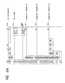
- Figs. 6A, 6B, 6C, 6D, 6E and 6F show programs for the programmable logic sequential controller.
- Y plus four digits, Y plus three digits, R plus three digits, X plus three digits, TD plus two digits and CU plus two digits denote the bit-joint-use internal output numbers of the controller, the numbers of the outputs from the controller to external devices, the bit word internal output numbers of the controller, the numbers of the input terminals of the controller from the external devices, the internal delay timers of the controller, and the internal counters of the controller, respectively.
- circuit numbers from (0018) to (0023) shown in Fig. 6A indicate a control process from the insertion of the base plate to the detection of the edge of the film.
- Circuit numbers from (0024) to (0029) shown in Fig. 6B indicate a control process from the peeling of the film to the sending-out of the base plate.
- Circuit numbers from (0044) to (0080) shown at (a) and (b) in Fig. 6C indicate the setting of the timers and the counters for control steps.
- Circuit numbers from (0098) to (0119) shown in Fig. 6D indicate a progress error control process.
- Circuit numbers from (0122) to (0132), those from (0136) to (0139) and those from (0141)to (0151) shown at (a), (b) and (c) in Fig. 6E indicate a controller output terminal control process in the main.
- Circuit numbers from (0184) to (0202) shown in Fig. 6F indicate an imaginary sensor working time control process.
- Fig. 7 is a time chart for describing the control in the film peeling method and the apparatus for practicing it.
- the method and the apparatus are the first embodiments of the present invention.
- each sign " " indicates the application of electric power to a motor or the turned-on state thereof, the reaction of a sensor or the turned-on state thereof, or the start of the forward action of a pneumatic cylinder
- each sign " " indicates the non-application of electric power to the motor or the turned-off state thereof, the non-reaction of the sensor or the turned-off state thereof, or the start of the backward action of the pneumatic cylinder.
- the upstream conveyor drive motor 214 starts rotating.
- the base plate centering start position sensor (WAPS) 203 which is a photoelectric sensor, reacts thereto and is turned on
- the base plate centering unit 202 starts centering the base plate to cause the center of the width thereof to coincide with that of the width of the upstream conveyor.
- a solenoid valve for feeding compressed air to the pneumatic cylinder 218 for moving the centering unit is opened.
- the base plate 1 is thus conveyed forward on the upstream conveyor and collides against the set-up stopper 212 so that if the leading edge of the base plate extends obliquely to the direction of the conveyance thereof, the edge is corrected to extend rectangularly thereto.
- the centering unit 202 has pinched the base plate 1 on both the side edges thereof, the base plate left side edge sensor (WALS-1) 210, which is a photoelectric sensor provided on the push bar 202B of the centering unit, and the base plate right side edge sensor (WALS-2) 211, which is a photoelectric sensor provided on the other push bar 202B of the centering unit, react thereto because the optical axes of the sensors are blocked by both the side edges of the base plate.
- WALS-1 which is a photoelectric sensor provided on the push bar 202B of the centering unit
- WALS-2 base plate right side edge sensor
- the centering unit 202 is put into such reverse action that the base plate push bars 202B thereof are returned to both the sides of the upstream conveyor.
- the base plate stopper 212 is dropped down, the base plate 1 is conveyed forward again.
- the upstream conveyor drive motor 214 continues to rotate since the start thereof.
- the base plate centering unit return sensor (WARS) 213 which is a proximity sensor to react in terms of the position of the piston of the pneumatic cylinder 218 for driving the centering unit 202 and is for confirming that the base plate push bars of the centering unit which is a sideward movement unit are returned to both the sides of the conveyor, reacts thereto, the programs for the control are executed sequentially. It is checked whether the base plate 1 already processed remains on the downstream conveyor of the apparatus and whether the film already peeled is not yet conveyed out by the film conveyor of the apparatus but remains on the conveyor. After no trouble is found out through the checking, the control programs are executed further.
- the delay timer (TD29) provided in the programmable logic sequential controller is put into action.
- the upstream conveyor drive motor 214 is shifted to low-speed rotation and the stylus of the film edge sensor (FES) 8, which is an electrostatic-capacity-reaction-type sensor provided over the base plate conveyance passage A-A so as to detect the leading edge of the film stuck to the base plate, is moved down toward the base plate conveyance passage (the stylus of the other film edge sensor 8 provided under the passage is moved up toward it).
- FES film edge sensor
- the upstream conveyor moving at a low speed conveys the base plate 1 forward so that the surfaces of copper foils on the base plate come into contact with the styli of the film edge sensors 8 vertically closed to each other, the sensors react thereto and are turned on.
- the base plate 1 is conveyed forward further, the surfaces of the films stuck to the copper foils come into contact with the styli of the film edge sensors 8 so that the sensors react thereto and are turned off.
- the stylus of the film edge sensor 8 which is the electrostatic-capacity-reaction-type sensor comes into contact with the electroconductive copper foil, the sensor reacts to the electrostatic capacity of the foil on the base plate 1.
- the stylus comes into contact with an electric insulator such as the film and air, the sensor 8 does not detect any electrostatic capacity and therefore does not react thereto.
- a step is thereafter taken at Y3200 in the control programs. After 0.1 second from the start of the previous step, it is begun that the air blowoff nozzle units 4 are set in such positions as to be obliquely oriented to the leading edges of the films, and the air guide plates 5 are set in positions near the base plate 1. Subsequently, the pneumatic vibration of the tip portions of film scratching heads which are the heads of the film buoy-up members 3 is started and the tip portions are pushed onto the films on the top and bottom of the base plate 1. At the same time, the styli of the film edge sensors 8 are put out of contact with the films or the base plate 1.
- one (6B) of the film pinch belts is moved toward the other belt 6A so that the film buoyed up and clinging to the air guide plate 5 is pinched between both the belts.
- the air guide lates 5 and the air blowoff nozzle units 4 are then moved away from the surfaces of the base plate 1 back prescribed positions.
- the upstream conveyor drive motor 214 is shifted back to high-speed rotation.
- the motor 215 for driving the belt conveyor for conveying the film is started.
- the downstream conveyor drive motor 216 is started, and film guide air for sending the peeled films is blown out from the fluid ejectors 12 simultaneously.
- the rotation speeds of the motors 214, 215 and 216 are regulated so that the upstream conveyor, the downstream conveyor and the belt conveyor are moved nearly at the same speed.
- the base plate 1 is transferred from the upstream conveyor onto the downstream conveyor while the cover films are peeled from the photosensitive resin layers on the base plate 1.
- BES base plate passing sensor
- the upstream conveyor drive motor 214 is put out of action.
- the film conveyance belt conveyor drive motor 215 is put out of action.
- the downstream conveyor drive motor 216 is put out of action.
- the base plate 1 stuck with the films is conveyed to the position of the peeling of the films at the leading edges thereof, as described above.
- the tightness of the contact of the films with the photosensitive resin layers on the base plate 1 is reduced at the leading edges of the films while the conveyance of the base plate is slowed but not stopped.
- the efficiency of the peeling of the films is thus enhanced through relatively simple constitution.
- the tightness can be securely reduced with high positional accuracy.
- a means for discharging the film while peeling it is reached by the film while the compressed air is blown to the tightness-reduced Portion of the film to peel it, the blowing of the air is stopped so that the consumption of the compressed air is less than that for peeling the whole film only by blowing such compressed air thereto. For that reason, the cost of operation of the film peeling apparatus is diminished. Since the sequential control in the film peeling method is automatically performed, the efficiency of the peeling of the films is enhanced further. Since the base plate 1 is forcibly conveyed when the leading edges of the films are detected and the tightness of the contact of the films with the photosensitive resin layers on the base plate is reduced at the leading edges of the films, the tightness can be more accurately and securely reduced.
- the film peeling apparatus including a means for conveying the base plate 1 stuck with the films, a means for reducing the tightness of the contact of the films with the photosensitive resin layers on the base plate at the leading edges of the films without stopping the conveyance of the base plate, a means for blowing the fluid in between the base plate and the tightness-reduced leading edge portions of the films, and a means for discharging the peeled films while peeling the tightness-reduced films includes the base plate insertion sensor 201, the base plate centering start position sensor 203, the film peeling sensors 204 and 205, the base plate passing sensor 206, the film edge sensors 8, the base plate check sensor 208, the base plate centering unit return sensors 213, and a sequential control means which operates on the basis of the output signals from the sensors. For that reason, the apparatus is capable of peeling the films automatically and efficiently.
- the second embodiments of the present invention in which scratchers are moved to make it needless to slow the conveyance of a base plate, are described in detail from now on.
- the second embodiments are nearly the same in basic constitution as the portions of the first embodiments shown in Figs. 1, 2A, 2B, 2C, 3A, 3B, 3C, 3D, 3E, 3F, 4, 5A, 5B and 5C, except that a base plate leading edge sensor 19 is provided in the second embodiments and the base plate stopper is not provided therein.
- Equivalents in the first and the second embodiments are denoted by the same reference symbols herein and not repeatedly described in detail hereinafter.
- FIG. 8A is a side view of a section which supports a film contact tightness reduction mechanism which operates at a speed synchronized with that of the conveyance of the base plate and is a feature of the second embodiments.
- Fig. 8B is a view of the section seen along an arrow Y shown in Fig. 8B.
- Fig. 9 is a perspective cutaway view of the section but does not show the film contact tightness reduction mechanism.
- guide rails 303 are secured to the upper portions of the right and left body frames 300 of a film peeling apparatus which is one of the second embodiments.
- Sliding blocks 304 are slidably fitted on the guide rails 303.
- Support members 305 are secured at one end of each thereof to the sliding blocks 304 and secured at the other ends thereof to the slide plates 306 of sliding parts.
- Each of the right and the left side plates 306 has an upper and a lower through holes 306A which are vertically slender holes and through which buoy-up member support rotary shafts 9 extend at both the ends thereof so that the shaft can be moved up and down in the holes.
- Conjoining members 313 are secured to the side plates 306.
- Coupling members 309 are attached to the coupling bars 310 at the other ends thereof.
- Crank members 307 are attached to the coupling members 309, and fitted with one-way bearings 308 on the shaft 2D of a conveyance drive roller 2, which extends through the frames 301 of the upstream conveyor of the apparatus.
- Electromagnetic clutches may be provided instead of the one-way bearings 308.
- pneumatic cylinder attaching plates 320 are secured to the tops of the upstream conveyor frames 301.
- Pneumatic cylinders 321 for an air guide plate 5 and a pich roller 2A up and down are attached to the attaching plates 320 at one end of each thereof.
- Support levers 318 for roller push plates 317 and hung plates 2C are rotatably supported at the lower portions of the levers by the attaching plates 320 at the other ends thereof so that the levers can be swung about the supported portions thereof.
- the piston rods of the pneumatic cylinders 321 are coupled to the support levers 318 at one end of each thereof by coupling members 319.
- Both the ends of the air guide plate and the hung plates 2C and the roller push plates 317 are located at the ends of the support levers 318 for the hung plates and the roller push plates.
- the shaft of the pich roller 2A is rotatably fitted in the roller push portion 317A of the lower portions of the roller push plates 317.
- Coupling angle members 314 are attached to the right and the left side slide plates 306. To the upper and lower portions of the coupling angle members 314 are secured at both the ends thereof fixed support members 7.
- Pneumatic cylinder attaching plates 315 are secured to the tops of the frames 302 of the downstream conveyor of the apparatus.
- Pneumatic cylinders 316 for moving the film buoy-up section of the apparatus are attached to the attaching plates 315.
- the piston rods of the cylinder 316 are secured to the conjoining members 313 at one end of the each thereof.
- Moving arms 322 are provided on the buoy-up member support rotary shafts 9 at both the ends thereof outside the right and the left frames 300 of the apparatus body in order that the movement of the upper buoy-up member support rotary shaft toward and away from the plane of the conveyance of the base plate 1 and the movement of the lower buoy-up member support rotary shaft toward and away from the plane are synchronized with each other.
- the moving arms 322 are coupled to each other by rotary arms 323 having through holes at the centers of the rotary arms.
- Shafts 337 are rotatably supported by the through holes and secured to the central portions of the side plates 306. Fig.
- FIG. 9 shows the state that the upper and the lower buoy-up member support rotary shafts 9 are moved away from the base plate conveyance plane.
- Coupling arms 326 and buoy-up member rotation arms 327 are provided on the buoy-up member support rotary shafts 9 at the ends thereof outside the moving arms 322.
- the central portions of the right and the left body frames 300 have upper and lower through holes in which shafts 338 are rotatably fitted.
- the shafts 338 function so that a film conveyor for discharging peeled films pinches the films.
- Arms 336 are secured at one end of each thereof to the upper shaft 338.
- Arms 334 are secured at the side edge of the central portion of each thereof to the lower shaft 338 and coupled at one end of each of the arms to the other arms 336 at the other ends thereof by coupling members 335.
- the arms 334 are coupled at the other ends thereof, by coupling members 333, to coupling members 332 attached to the piston rods of pneumatic cylinders 331 which are for pinching the peeled films and are attached to pneumatic cylinder attaching plates 330 secured to the lower parts of the side portions of the body frames 300.
- a sensor securing plate 20 is attached at one end thereof to the fixed support member 7 near its portion to which an air blowoff nozzle unit attaching plate 18 is secured.
- a base plate leading edge sensor 19 is secured to the sensor securing plate 20 at the other end thereof.
- Fig.10 is a time chart of the operation.
- a start switch on a control panel 107 When a start switch on a control panel 107 is turned on, the film peeling apparatus is put in a stand-by state for automatic operation.
- a base plate insertion sensor (BLS) 201 provided at the inlet portion detects the base plate so that a timer 1 provided in the programmable logic sequential controller of the apparatus is put into action.
- an upstream conveyor drive motor 214 (M2) is started so that the conveyance rollers 102 of the upstream conveyor begin to rotate to convey the base plate 1 on the rollers.
- a centering drive pneumatic cylinder 218 is put into action so that a centering unit 202 starts the centering (sideward movement) of the base plate 1 being conveyed.
- the centering unit 202 On the basis of detection signals from the sensors 210 and 211, the centering unit 202 is put into reverse action opposite to the centering action thereof, so that the unit is returned to its original position wherein it was before being put into the centering action.
- the original position is such a position that a base plate centering unit return sensor (WARS) 213 attached to the centering drive pneumatic cylinder 218 detects the position of the piston of the cylinder in order to stop the centering unit 202.
- WARS base plate centering unit return sensor
- the base plate 1 is conveyed throughout the centering action of the centering unit 202 and the return thereof to the original position.
- a timer 2 provided in the programmable logic sequential controller is put into action on the basis of a detection signal from the base plate centering start position sensor 203.
- compressed air is introduced into pneumatic cylinders for vertical movement members 24 for an upper and a lower film edge sensors 8 so that the piston rods of the cylinders are moved toward the conveyance passage A-A for the base plate 1 (Fig. 3F).
- the film edge sensors (FES-1 and FES-2) 8 are pushed by the members 24 so that the styli of the tip portions of the sensors are moved toward the base plate conveyance passage A-A and cross with each other without contact with each other.
- the pneumatic cylinders 321 for moving the air guide plate 5 and the pinch roller 2A are put into action so that the roller pushes the base plate 1 and the upper air guide plate is moved down toward the base plate.
- the base plate leading edge sensor (BEDS) 19 is disposed slightly downstream of the tip of the stylus of the tip portion of the film edge sensor 8 in the second embodiments.
- the base plate edge detection signal sent out from the sensor 19 is put in use.
- a timer 3 provided in the programmable logic sequential controller is put into action on the basis of a detection signal generated as a result of the detection.
- the set time which is 0 second to 0.1 second, for example
- the film edge sensors 8 are moved away from the base plate conveyance passage A-A back to the original positions of the sensors.
- the pneumatic vibration of the tips of film buoy-up members 3, which are the film scratchers, is started, and pneumatic cylinders 325 for vertically moving the buoy-up members are put into action so that the tips of the buoy-up members are pushed onto the surfaces of the films on the top and bottom of the base plate 1 while being vibrated.
- the period for which the tips of the film buoy-up members 3 are pushed onto the films is set by timers 4 and 7 provided in the programmable logic sequential controller.
- the pneumatic cylinders 316 for moving the film buoy-up members 3 are put into action so that a film buoy-up unit supported by the sliding blocks 304 begins to move as a whole in the direction of the conveyance of the base plate 1.
- the film buoy-up unit is coupled to a drive shaft for the conveyance rollers 102 of the upstream conveyor by the coupling bars 310, the coupling members 309 and 311, the crank members 307 and the one-way bearings 308, the bearings are engaged at the time of the movement of the unit in the same direction as the conveyance of the base plate 1 so that the unit is moved at a speed synchronized with that of the conveyance of the base plate.
- the one-way bearings 308 are not engaged, so that the speed of the upstream conveyor is not changed.
- the timer 4 provided in the programmable logic sequential controller is put into action.
- pneumatic cylinders 329 for swinging the film buoy-up members 3 are put into action so that the members are swung along the direction of the conveyance of the base plate 1 while the tip portion of the members are vibrated, thus reducing the tightness of the contact of the films with the base plate at the leading edges thereof.
- a film conveyance belt drive motor 215 is put into action when the films are buoyed up from the base plate so that the upper and the lower film peeling sensors 204 and 205 react thereto. At that time, a timer 5 provided in the controller is put into action. The motor 215 is kept in action since that time. When the set time of the timer 5 has elapsed, a film pinch belt 6B is moved toward another belt 6A so that each buoy-up film clinging to the air guide plate 5 is pinched between the belts and conveyed by them. The air guide plate 5 and the pinch roller 2A are moved away from the surface of the base plate 1 back to the original positions wherein the air guide plate and the roller were before being put into action. A downstream conveyor drive motor 216 is started. Film guide air for discharging the peeled films from the film peeling apparatus is blown out from fluid ejectors 12 simultaneously.
- the base plate 1 from which the films are already peeled is transferred from the upstream conveyor of the film peeling apparatus onto the downstream conveyor thereof.
- a base plate passing sensor 206 BES
- a timer 6 provided in the controller is put into action.
- the upstream conveyor drive motor 214 is put out of action.
- the downstream conveyor drive motor 216 is put out of action.
- the motors 214 and 216 are not put out of action but remain in action.
- crank members 307 are provided in the second embodiments so as to move the film buoy-up unit in the same direction as the conveyance of the base plate, racks and pinions may be provided instead of the crank members.
- the base plate 1 stuck with the films is conveyed to the position of the peeling of the films at the leading edges thereof.
- the tightness of the contact of the films with the base plate 1 is reduced at the leading edges of the films while the film buoy-up unit is moved at the speed synchronized with that of the conveyance of the base plate and the speed of the conveyance is substantially unchanged.
- the air is blown in between the base plate and the tightness-reduced films so that the films are automatically discharged while being peeled from the base plate.
- the efficiency of the peeling of the films is more enhanced.
- the base plate is conveyed to the position wherein the films are peeled from the base plate at the leading edges of the films.
- the tightness of the contact of the films with the base plate is reduced at the leading edges of the films while the film buoy-up unit is moved at the speed synchronized with that of the conveyance of the base plate and the speed of the conveyance is substantially unchanged.
- the air is blown in between the base plate and the tightness-reduced films at the leading edges so that the films are discharged while being peeled from the base plate. The films are thus peeled from the base plate automatically so that the efficiency of the peeling is enhanced.
- the present invention is not confined to the embodiments described above, but may be embodied or practiced in other various ways without departing from the spirit or essential character thereof.
- the present invention can be applied to peel off a film on only one suface of the base plate.
Landscapes
- Engineering & Computer Science (AREA)
- Manufacturing & Machinery (AREA)
- Physics & Mathematics (AREA)
- General Physics & Mathematics (AREA)
- Microelectronics & Electronic Packaging (AREA)
- Separation, Sorting, Adjustment, Or Bending Of Sheets To Be Conveyed (AREA)
- Manufacturing Of Printed Circuit Boards (AREA)
- Folding Of Thin Sheet-Like Materials, Special Discharging Devices, And Others (AREA)
Abstract
Description
- The present invention relates to an art in which a film stuck to a plate is peeled therefrom and discharged.
- In a printed circuit board for an electronic machine such as a computer, wirings of copper or the like are provided in a prescribed pattern on one or both sides of an electrically insulating plate. The printed circuit board is manufactured as described from now on. A stratified body consisting of a photosensitive resin layer, which is a photoresist layer, and a cover film, which is made of a light-transmissible resin and protects the photosensitive resin layer, is first stuck, under heat and pressure, to an electroconductive layer provided on the plate. A wiring pattern film is then overlaid on the stratified body. The photosensitive resin layer is thereafter exposed to light through the wiring pattern film and the cover film for a prescribed time. After the wiring pattern film and the cover film are removed, the exposed photosensitive resin layer is developed so that an etching mask pattern is formed. The unnecessary portions of the electroconductive layer are thereafter removed by etching. The remaining portions of the photosensitive resin layer are then removed. The printed circuit board having the wirings in the prescribed pattern is thus manufactured.
- An automatic film peeling apparatus, which is a machine for automatically peeling such a film from such a layer, was developed as disclosed in the Japanese Patent Application (OPI) No. 271356/89 (the term "OPI" as used herein means an "unexamined published application") corresponding to USSN 342,827. The apparatus peels a part of the film stuck to a plate, peels the other parts of the film starting with the border of the latter part on the former, and then discharges the peeled film. The apparatus includes a first film conveyance means by which the film having the former part peeled from the plate is conveyed upward over the surface of the plate while the film is pinched by a belt conveyor so that the film is peeled from the plate, and a second film conveyance means by which air is blown to the film conveyed by the first film conveyance means, so that the film is conveyed to a peeled film container.
- As for the automatic film peeling apparatus mentioned above, the plate is temporarily stopped when the tightness of the contact between the former part of the film and the plate is reduced or the part is peeled from the plate. For that reason, the efficiency of the peeling of the film from the plate is low. This is a problem.
- The present invention was made in order to solve the above-mentioned problem.
- Accordingly, it is the first object of the present invention to provide an art in which the tightness of the contact of films with a base plate is reduced at the leading edges of the films without stopping the conveyance of the base plate while peeling them from the base plate, to enhance the efficiency of the peeling of the film.
- It is the second object of the present invention to provide an art in which the first object is attained through relatively simple constitution.
- It is the third object of the present invention to provide an art in which films stuck to a base plate are rapidly peeled therefrom, conveyed and discharged without changing the speed of the conveyance of the base plate.
- The above-mentioned and other objects of the present invention as well as the novel features thereof will be apparent from the description herein and the drawings attached hereto.
- In a method provided in accordance with the present invention to attain the first object, the films stuck to the base plate are peeled therefrom. The method has a major feature that the base plate stuck with the films is conveyed to a position wherein the films are peeled at the leading edges thereof from the base plate; the tightness of the contact of the films with the base plate is reduced at the leading edge of the films while the difference between the speed of the conveyance of the base plate and that of the movement of a film contact tightness reduction means is decreased and the conveyance of the base plate is not stopped; and a fluid is blown into the gaps between the base plate and the tightness-reduced films at the leading edges thereof to discharge the films while peeling the tightness-reduced films from the base plate.
- In the method, the base plates stuck with the films is conveyed to the position wherein the films are peeled at the leading edges thereof from the base plate. In the method, the tightness of the contact of the films with the base plate is reduced at the leading edges of the films without stopping the conveyance of the base plate. In the method, the fluid is blown into the gaps between the base plate and the tightness-reduced films at the leading edges thereof to discharge the films while peeling the tightness-reduced films from the base plate. As a result, the efficiency of the peeling of the films is enhanced.
- If the conveyance of the baseplate is temporarily stopped in a prescribed position on a base plate conveyance means so that the obliqueness of the base plate is corrected and the base plate is centered before the tightness of the contact of the films with the base plate is reduced at the leading edges thereof, the base plate is accurately positioned so that the tightness of the contact of the films with the base plate can be smoothly reduced at the leading edges of the films.
- If the speed of the conveyance of the base plate is decreased when the base plate is conveyed to a prescribed position upstream of the position wherein the films are peeled from the base plate at the leading edges of the films and the tightness of the contact of the films with the base plate is reduced at the leading edges of the films, the reduction can smoothly performed through relative simple constitution. The second object can thus be attained.
- If the decreased speed of the conveyance of the base plate is altered back to the original level in discharging the films while peeling them, the base plate is rapidly conveyed at the time of the discharge of the films so as to enhance the efficiency of the peeling of the films.
- If the arrival of the leading edges of the films at the prescribed position wherein the tightness of the contact of the films with the base plate is reduced at the leading edges thereof is detected so that a means for blowing the fluid is set in such a position to be obliquely oriented to the leading edges of the films and fluid guide plates are set in positions near the base plate, the films are smoothly peeled by blowing the fluid thereto.
- Furthermore, if a height of the fluid guide plate from the base plate top surface is maintained in a prescribed range in response to a height of an upper roller, it is possible to raise the film by the blow of the flow without fail irrespective of a thickness of the base plate.
- If the cone-shaped tip portions of film scratchers are vibrated in the axial directions thereof in contact with the surface of the film while extending downward obliquely to the direction of the conveyance of the base plate, to impart vibratory energy to the film to reduce the tightness of the contact thereof with the base plate at the leading edge of the film, the reduction is surely performed without stopping the conveyance of the base plate.
- If the film scratchers are moved by a prescribed length in the direction of the conveyance of the base plate relative thereto while being in contact with the surface of the film, the reduction is more surely performed.
- If the base plate is forcibly conveyed in reducing the tightness of the contact of the films with the base plate at the leading edges of the films, the base plate can be surely conveyed without stopping the conveyance thereof, regardless of the operative forces of the film scratchers and so forth.
- In particular, if by using a gear having a large module ratio the upper pinch roller is forcibly rotated by the lower roller, it is possible to positively feed the baes plate regardless of a change of the thickness of the base plate.
- If fluid blowoff nozzle units which have fluid ejection holes oriented to the film scratcher contact portions of the gaps between the base plate and the films and have fluid ejection holes oriented to the leading edges of the films near the film scratcher contact portions are provided so that the nozzle units are preferably located between the conveyance passage for the base plate and the film scratchers near the scratchers, the films can be surely peeled from the base plate by blowing the fluid to the films.
- If the leading edge portions of the films, which are peeled from the base plate by blowing the fluid to the films, are caused to cling to the fluid guide plates by the pressure of the fluid, the peeling of the films and the introduction of them into discharge passages through the blowing of the fluid can be smoothly performed.
- If operation for reducing the tightness of the contact of the films with the base plate at the leading edges of the films is stopped through detecting that the peeled leading edge portions of the films have clung to the fluid guide plates, the operation can be precisely terminated.
- If blowing the fluid to the tightness-reduced portions of the films to peel them from the base plate is stopped when the films have arrived from the stage of the blowing of the fluid to the films at the stage of the discharge of the films along with the peeling thereof, the blowing of the fluid can be precisely terminated.
- If the tightness-reduced films are pinched by film catch belts so as to be discharged while being peeled, the films can be rapidly peeled.
- If peeled film guides shaped as rods and made of an electroconductive substance and/or an ion generator is used, static electricity can be eliminated from the films in discharge passages for the peeled films to smoothly discharge the films.
- If the films peeled from both the side of the base plate are discharged into a common film container, it is easy to accommodate the peeled films.
- If the steps of the method are subjected to sequential control through the use of the relays and timers of a programmable logic sequential controller, the steps can be automatically controlled.
- A film peeling apparatus provided in accordance with the present invention to attain the second object is characterized by including a base plate conveyance means for conveying the base plate stuck with the films; a base plate centering start position sensor for detecting that the base plate is conveyed forward on the conveyance means and reaches a prescribed position upstream of the position of peeling of the films from the base plate; a base plate centering unit which is put into action on the base of the output from the centering start position sensor so as to move the center of the width of the base plate to the center line of the conveyance means; a base plate slowing means for decreasing the speed of the conveyance of the base plate at the end of the action of the centering unit; film edge sensors for detecting the leading edges of the films stuck to the base plate; a film contact tightness reduction means which is put into action on the basis of the outputs from the film edge sensors so as to reduce the tightness of the contact of the films with the base plate at the leading edges of the films without stopping the conveyance of the base plate; a fluid blowing means for blowing the fluid into the gaps between the base plate and the leading edges of the films reduced in the tightness of the contact thereof with the base plate by the tightness reduction means, to separate the films from the base plate; film peeling sensors for detecting that the separated films have entered into film discharge passages; a means for altering the decreased speed of the conveyance of the base plate back to the original level thereof on the basis of the outputs from the film peeling sensors; and a film pinch means for discharging the films while pinching the separated films and peeling them from the base plate.
- In the film peeling apparatus, the base plate conveyance means, the base plate centering start position sensor, the base plate centering unit, the base plate slowing means, the film edge sensors, the film contact tightness reduction means, the fluid blowing means, the film peeling sensors and the film pinch means are provided so that the base plates stuck with the films is conveyed to the position of the peeling of the leading edge portions for the films, the tightness of the contact of the films with the base plate is reduced at the leading edges of the films without stopping the conveyance of the base plate, and the films are discharged while being peeled after the reduction in the tightness of the contact. For that reason, the films can be automatically and efficiently peeled from the base plate.
- If a base plate insertion sensor for detecting the insertion of the base plate into the inlet portion of the base plate conveyance means in order to start the conveyance of the base plate is provided in the film peeling apparatus, the conveyance can be automatically started.
- If a base plate passing sensor for detecting the complete passing of the trailing edge of the base plate through the film peeling position in order to stop the conveyance of the base plate and the films is provided in the apparatus, the conveyance can be automatically stopped.
- If guide members and guide rollers are provided in the apparatus so as to guide the base plate to prevent it from sagging, even if the thickness of the base plate is small, the films can be smoothly peeled from the base plate regardless of the thickness thereof.
- If peeled film guide members for guiding the peeled films having passed through the film pinch means made of film catch belts, for example, and fluid ducts for discharging the films guided by the guide members are provided in the apparatus, the peeled films can be smoothly discharged.
- If a return sensor for detecting the termination of the action of the base plate centering unit is provided in the apparatus and is a magnetic sensor which reacts to the position of an actuator for driving the centering unit, the termination can be detected without contact with the centering unit.
- If the film edge sensors are of electrostatic capacity reaction type, the edges of the films can be precisely detected in terms of the difference in electrostatic capacity.
- In a method provided in accordance with the present invention to attain the third object, the films stuck to the base plate are peeled therefrom. The method has a major feature that the base plate stuck with the films is conveyed to a position wherein the films are peeled from the base plate at the leading edges of the films; the tightness of the contact of the films with the base plate is reduced at the leading edges of the films while a film contact tightness reduction mechanism is moved, for a prescribed time, at a speed synchronized with that of the conveyance of the base plate and the speed of the conveyance is substantially unchanged; and a fluid is blown into the gaps between the base plate and the tightness-reduced films at the leading edges thereof to discharge the films while peeling the tightness-reduced films.
- In the method, the base plate stuck with the films is conveyed to the position of the peeling of the films at the leading edges thereof, the tightness of the contact of the films with the base plate is reduced at the leading edges of the films while the film contact tightness reduction mechanism is moved at the speed synchronized with that of the conveyance of the base plate and the speed of the conveyance is substantially unchanged, and the fluid is blown into the gaps between the base plate and the tightness-reduced films at the leading edges thereof to discharge the films while peeling the tightness-reduced films. For that reason, the efficiency of the peeling of the films can be more enhanced.
- A film peeling apparatus provided in accordance with the present invention to attain the third object includes a base plate conveyance means having conveyance rollers; a base plate centering start position sensor; a base plate centering unit; a base plate leading edge sensor; a film contact tightness reduction means; a fluid blowing means; a support frame fitted with the tightness reduction means and the fluid blowing means and movable in the direction of the conveyance of the base plate; a means for moving the support frame synchronously with the rotation of the conveyance rollers for a prescribed time so that the speed of the conveyance of the base plate is substantially unchanged during the reduction in the tightness of the contact of the films with the base plate; film peeling sensors; a film discharge means; and a sequential control means which operates on the basis of the output signals from the sensors. The base plate is conveyed to the position wherein the films are peeled from the base plate at the leading edges of the films. The tightness of the contact of the films with the base plate is reduced at the leading edges of the films while the support frame is moved at a speed synchoronized with that of the conveyance of the base plate and the speed of the conveyance is substantially unchanged. A fluid is blown in between the base plate and the leading edges of the tightness-reduced films to discharge the films while peeling the tightness-reduced films. As a result, the efficiency of the peeling of the films can be more enhanced.
- If the base plate conveyance means has a base plate push conveyance roller and is provided with a mechanism which drives the roller on the bases of the output signal from the base plate leading edge sensor so as to push the base plate and stops the pushing thereof after a prescribed time, the base plate can be surely and synchronously conveyed even during the reduction of the tightness of the contact of the films with the base plate.
- If the means for moving the support frame has a crank mechanism which is driven synchornously with the rotation of the base plate conveyance rollers, the support frame can be easily moved in the direction for the conveyance of the base plate.
- If the crank mechanism includes crank members coupled at one end of each thereof to the support frame and includes an one-way clutch means for synchronizing the movement of the crank members and the rotation of the base plate conveyance rollers with each other only while the tightness of the contact of the films with the base plate is reduced at the leading edges of the films, the movement of the support frame does not interfere with the rotation of the conveyance rollers.
- If the base plate leading edge sensor is provided near the film edge sensors, the base plate can be surely detected even if the films are stuck to the whole surfaces of the base plate.
- The exact nature of this invention as well as other objects and advantages thereof will be apparent from consideration of the following specification relating to the accompanying drawings, in which like reference characters designate the same or similar parts throughout the figures thereof and wherein:
- Fig. 1 is a perspective schematic view of a film peeling apparatus which is a first embodiment of the present invention and peels films from a base plate for a printed circuit board;
- Fig. 2A is a view showing the detail of the film peeling mechanism in the vicinity of the pneumatic film conveyance box shown in Fig. 1;
- Fig. 2B is a partially enlarged view showing the vicinity of the upper pinch roller on an enlarged scale shown in Fig. 2A;
- Fig. 2C is a view showing the gear for driving the upper pinch roller shown in Fig. 2A.
- Fig. 3A is a view of a film contact tightness reduction mechanism seen oppositely to the direction of the conveyance of the base plate;
- Fig. 3B is a side view of the tightness reduction mechanism seen along an arrow L shown in fig. 3A;
- Fig. 3C is a perspective view of the tightness reduction mechanism;
- Fig. 3D is a perspective view of a fluid blower;
- Fig. 3E is a plan view of Fig. 3D;
- Fig. 3F is a perspective view of a film edge detection mechanism;
- Fig. 4 is a schematic view for describing a film peeling method and the control means of the first embodiment;
- Fig. 5A is a view for describing the constitution of a base plate centering unit;
- Fig. 5B is a sectional view of the centering unit along a line X-X shown in Fig. 5A;
- Fig. 5C is a view for describing the operating portion of the centering unit;
- Figs. 6A, 6B, 6C, 6D, 6E and 6F are diagrams of programs for the programmable controller of the first embodiment;
- Fig. 7 is a time chart for describing control in the first embodiment;
- Fig. 8A is a side view of a portion for supporting a film contact tightness reduction mechanism which is a feature of a second embodiment of the present invention and operates at a speed synchronized with that of the conveyance of a base plate;
- Fig. 8B is a view of the portion seen along an arrow Y shown in Fig. 8A;
- Fig. 9 is a perspective cutaway view of the portion shown in Figs. 8A and 8B and does not show the film contact tightness reduction mechanism which would be shown in the central part of the drawing; and
- Fig. 10 is a simplified time chart of operation in the second embodiment.
- Embodiments of the present invention are hereafter described in detail with reference to the drawings attached hereto. The embodiments are applied to a method of peeling a protective cover film from a base plate for a printed circuit and an apparatus for practicing the method. Equivalents shown in the drawings are denoted by the same reference symbols and not repeatedly described in detail, hereinafter.
- Fig. 1 is a perspective schematic view of the apparatus according to a first embodiment by which the protective cover film is peeled from the base plate. Fig. 2A is a detailed view of the pneumatic film conveyance box of the apparatus and the vicinity of the box.
- The base plate conveyance mechanism of the apparatus includes plate
conveyance roller units body 100 of the apparatus, in the plate advancing direction A as shown in Fig. 1. Anair duct rest 103 is provided over the plateconveyance roller unit 102. One end of theair duct rest 103 is fixed to thebody 100. Anair duct 104 made of a transparent material is provided on theair duct rest 103. The left side (as viewed in the plate advancing direction A) of theair duct 104 is connected to a top opening of a peeledfilm discharge duct 105 having a large number of airpressure reduction holes 105A on the side thereof.Air passage holes 104D are provided in the right side of theair duct 104. The top and front side of theair duct 104 are integrated with each other to constitute a part of acover 104A attached to thebody 104C of the duct byhinges 104B so that the cover can be opened and closed. - As shown in Fig. 2A, in a right side of the interior of the
air duct 104, there are disposed an ion-generator (i.e., static electricity remover) 110 for removing static electricity from the peeled film,blower fans - The outlet of the peeled
film discharge duct 105 is located over a peeledfilm container 106, which receives the peeled film. Thecontainer 106 includes abase 106A having a large number of air pressure reduction holes, a nettedportion 106B, andcasters 106C. - A
control panel 107 is provided on a side of thebody 100 of the apparatus. A warninglamp 108 is provided on the top of theapparatus body 100. - As shown in Fig. 2A, the film buoy-up
members 3 of a film buoy-up unit such as a pneumatic vibrator type film scratcher, the fluidblowoff nozzle members 4 of a fluid blowing unit,air guide plates 5, which serve as peeling assistant plates, and afilm conveyor 6, which serves as a film discharger, are provided along a base plate conveyance passage A-A on the base plate conveyance mechanism. - The
base plate 1 for the printed circuit is made of an electric insulator coated with an electroconductive layer of copper or the like on one or both sides of the base plate. A stratified body consisting of a photosensitive resin layer, which is a photoresist layer, and the cover film, which is a protective film, is stuck, under heat and pressure, to the electroconductive layer of theplate 1 in advance. Theplate 1 is brought to the film peeling apparatus after the photosensitive resin layer is exposed to light through a prescribed wiring pattern film overlaid on the stratified body. Theplate 1 is conveyed by thedrive rollers 2 of the plateconveyance roller units - A base plate
push conveyance roller 2A, which is a pinch roller, is provided so that abase plate 1 for a printed circuit board is prevented from being displaced out of centered state when the base plate passes on the roller and cover films are peeled from the base plate. - As shown in more detail in Fig, 2B, the
upper pinch roller 2A is depressed against the plate surface from above by aroller push plate 317 so that the plate may be positively fed by the rotation of theupper roller 2A. Aroller push portion 317A of theroller push plate 317 has an inverted U-shape so as to permit theupper roller 2A movable downwardly. Alever 318 carries theroller push plate 317. Thelever 318 has a U-shaped connectionmember receiving portion 318A which in turn engages acoupling member 319 fixed to a tip end of a rod of the push roller elevating/loweringpneumatic cylinder 321. - Therefore, when the rod of the
pneumatic cylinder 321 is extended or retracted, the roller pushplate support lever 318 is rotated about apivot 318B, to thereby move theroller push plate 317 up and down. Since theair guide plate 5 is provided on theroller push plate 317, the vertical position of theair guide plate 5 is also changed in response to the vertical position change of theupper roller 2A (i.e., the roller push plate 317) in correspondence with the change of the thickness of thebase plate 1. Accordingly, even if the thickness of thebase plate 1 is changed, it is possible to automatically keep in a predetermined range (0.5-1.5 mm for example), suitable for keeping air flow and raising the film, a distance between theair guide plate 5 and the base plate top surface. It should be noted that the vertical position of theair guide plate 5 is manually adjustable in response to the thickness of thebase plate 1. - As shown in more detail in Fig. 2C, the above-mentioned
upper pinch roller 2A is forcibly driven by a pair ofgears lower drive roller 2 and theupper pinch roller 2A and engaged with each other with a large module ratio. The reason why the large module ratio gears are used is that, when the thickness of thebase plate 1 is changed, the space between thepinch roller 2A and thedrive roller 2 is also changed. In this manner, if the gears having the large module ratio, i.e., long teeth are used, even if the space between the engaged teeth is enlarged, since the engagement allowance is large, it is possible to responds to the change of the gear tooth space due to the change in thickness of the base plate. It is thus possible to ensure the operation of thepinch roller 2A. In the embodiment, when therollers - As described above, even during the scratch operation, by forcibly drivingly rotating the
upper pinch roller 2A in synchronism with thelower drive roller 2, the base plate is positively delivered. Thus, the scratcher and the base plate may be moved relative to each other. Accordingly, it is possible to avoid a fear that the base plate would be drawn by the scratcher during the scratch operation. It is possible to loosen the film smoothly and positively. - Fig. 3A is a view of a film contact tightness reduction mechanism seen oppositely to the direction of the conveyance of the
base plate 1. Fig. 3B is a side view of the mechanism seen along an arrow L shown in Fig. 3A. Fig. 3C is a perspective view of the mechanism. Fig. 3D is a perspective view of a film edge detection mechanism. - In a film buoy-up unit, at least one
support member 10 for a film buoy-upmember 3 is secured to each of buoy-up membersupport rotary shafts 9 provided over and under a base plate conveyance plane, as shown in Figs. 2A, 3A, 3B and 3C. A slidingblock 13 is attached to thesupport member 10, and fitted on aguide rail 14 so that the block can be moved up and down. A buoy-upmember support block 16 is secured to theguide rail 14. The film buoy-upmember 3 is attached to the buoy-upmember support block 16, and extends obliquely to the base plate conveyance plane. The upper portion of thesupport member 10 for the film buoy-upmember 3 has a through hole through which along screw 15 slightly smaller in diameter than the hole extends. Aspring 17 is provided on thelong screw 15 at one end thereof. Thescrew 15 is secured at the other end thereof to the buoy-upmember support block 16. - The tip portion of the film buoy-up
member 3 is conically shaped, and can be vibrated by a pneumatic vibrator which causes the vibration of 2,000 to 3,000 strokes per minute, for example. The tip portion of the buoy-upmember 3 is constituted to vibrate and push the edge portion of a stratified film consisting of a photosensitive resin layer and the cover film, to impart energy to the edge portion of the stratified film to buoy up the cover film from the photosensitive resin layer at the edge portion. The reason why only the cover film of the edge portion to which the energy is imparted is buoyed up is presumed to be that the cover film is higher in extensibility than the photosensitive resin layer and the adhesive power between the resin layer and an electroconductive layer on the base plate is stronger than that between the resin layer and the cover film. - As shown in Figs. 3B and 3C, a fluid blower is made of fluid
blowoff nozzle units 4 attached to fluid blowoff nozzleunit attaching plates 18 at one end of each thereof. Theplates 18 are secured to fixedsupport members 7 provided over and under the base plate conveyance plane. A pressurized fluid, which is a gas such as air and an inert gas or is a liquid such as water, is blown off from each of thenozzle units 4. In this embodiment, the fluid is air. The fluidblowoff nozzle unit 4 is located near tip of the film buoy-upmember 3. The tip of thenozzle unit 4 is oriented to the leading edge of the stratified film stuck to the base plate, to directly blow the fluid into the gap between the photosensitive resin layer and the cover film buoyed up therefrom by the film buoy-upmember 3. As shown in Figs. 3D and 3E the tip portion of thenozzle unit 4 has a plurality of fluid ejection holes 4A, 4B, one (4A) of which is oriented to the tip of the film buoy-upmember 3 or to the above-mentioned gap and the others (4B) of which are oriented to the edge of the film at the right and left of the tip of the buoy-up member near the tip. The reason why the plurality of fluid ejection holes are provided in thenozzle unit 4 is to surely peel the cover film by blowing the fluid thereto. The fluid is fed to thenozzle units 4 through a single fluid feed pipe. - At the center of the film buoy-up unit, film edge detection
member attaching blocks 22 are supported by fixedmembers 21 attached to the upper and the lowerfixed support members 7, as shown in Figs. 3A and 3F, so that the blocks can be moved backward and forward. The position of each of theblocks 22 can be shifted backward and forward by a film edge detection memberposition adjusting knob 23. Afilm edge sensor 8 is rotatably supported at one end thereof by the attachingblock 22 at the tip thereof. Avertical movement member 24 for thefilm edge sensor 8 is rotatably supported by the attachingblock 22 at the central portion thereof. One end of thevertical movement member 24 is secured to the attachingblock 22 through a compact pneumatic cylinder. -
Sensor securing members 25 are attached at one end of each thereof to the upper and the lowerfixed support members 7 near the film edge sensor attaching blocks 22. Afilm peeling sensor 204 is secured to thesensor securing member 25 at the other end thereof over the base plate conveyance plane. Anotherfilm peeling sensor 205 is secured to the othersensor securing member 25 at the other end thereof under the base plate conveyance plane. - Buoying up the edge of the film on the
base plate 1 and peeling the film at the edge are nearly the same in principle as those described in the Japanese Patent Application (OPI) No. 271356/89 (the term "OPI" as used herein means an "unexamined published application"), and are therefore not described in detail herein. - The cover film peeled from the photosensitive resin layer at the leading edge of the base plate by the air ejected from the air
blowoff nozzle units 4 of the fluid blower is pushed onto theair guide plate 5 by the pressure of the air. Guide wheels 11 are provided to guide thebase plate 1 to prevent it from sagging at the leading edge thereof, even if the thickness of the base plate is small. The reason why the guide wheels 11 are provided is that the film buoy-upmembers 3 and the airblowoff nozzle units 4 are provided in or at the film buoy-up unit in such a manner that conveyance rollers cannot be disposed at them. The guide wheels 11 are particularly effective for base plates of large width. - As shown in Fig. 2A, a
film conveyor 6 includes an upper and a lower film conveyance units in the main. The upper film conveyance unit is provided over the conveyance passage A-A for thebase plate 1. The lower film conveyance unit is provided under the base plate conveyance passage A-A. The upper film conveyance unit includes a firstfilm conveyance section film guide members 6C and a secondfilm conveyance section 6D. The peeled film is conveyed by the first and the secondfilm conveyance sections film guide member 6C in a direction shown by an arrow M in Fig. 2. Theguide members 6C act to alter the direction of the conveyance of the peeled film in such a manner that the vertical direction of the conveyance of the peeled film is changed into a horizontal direction which is parallel with the base plate conveyance passage A-A but opposite to the direction of the conveyance of thebase plate 1. Theguide members 6C are made of rods so as to minimize contacting area with the speed film and disposed at an interval along a direction extending across the base plate conveyance passage A-A. For example, theguide members 6C are made of an electroconductive substance such as stainless steel wire so as to eliminate static electricity generated on the peeled film in the peeling or/and conveyance thereof. The peeledfilm guide members 6C act to prevent the peeled film from being involved by a roller 6Aa for a fixedconveyance belt 6A and/or a roller 6Bb for amovable conveyance belt 6B during the conveyance of the film from the firstfilm conveyance section film conveyance section 6D. - A
fluid ejector 12 and anion generator 15, which is an electricity eliminator, are provided near the peeledfilm guide members 6C. Thefluid ejector 12 ejects a fluid in a direction shown by an arrow N in Fig. 2A. Theion generator 15 acts to eliminate static electricity from the peeled film to prevent it from clinging to theguide members 6C due to the electricity when the film is conveyed from the firstfilm conveyance section film conveyance section 6D. - Shown at 2C in Fig. 2A is a hung plate for moving the upper
air guide plate 6 down toward thebase plate 1 and up away therefrom. Thehung plate 2C is coupled at both the ends thereof to pneumatic cylinders for moving the hung plate, and is also coupled at both the ends thereof to aholder 317 for holding the rotary shaft of the base platepush conveyance roller 2A. - Fig. 2A also shows the fixed
support members 7, thefilm edge sensors 8, the film buoy-up membersupport rotary shafts 9 coupled at both the ends thereof to crank mechanisms, and rollers 6Ba', 6Ab, 6Bb and 6Bc. - The
film catch belts belts - As shown in Figs. 1 and 2A, the second
film conveyance section 6D is provided on anair duct rest 103. Thesection 6D is made of anair duct 104 coupled to a coverfilm discharge duct 105. The top and one side of theair duct 104 is integrally formed to be acover portion 104A attached to thebody 104C of the duct by ahinge 104B so as to be openable and closable. Thecover portion 104A has air passage holes 104D in prescribed positions. Blowingfans body 104C of theduct 104 and located so as to face the air passage holes 104D. - Fig. 4 is a schematic view for describing a film peeling method of the first embodiment of the present invention. Fig. 4 is also for describing the control means of an apparatus for practicing the film peeling method. Fig. 5A shows the constitution of the base plate centering unit of the apparatus. Fig. 5B is a sectional view of the centering unit along a line X-X shown in Fig. 5A. Fig. 5C shows the operating portion of the centering unit. A base plate insertion sensor (BLS) 201 is provided at the inlet portion of the base plate conveyance passage A-A, at which the
base plate 1 is conveyed by the upstream conveyor of the apparatus. The baseplate centering unit 202, which is base plate sideward movement unit, includes centeringpins 202A, which are put into contact with both the side edges of thebase plate 1 which extend in the direction of the conveyance thereof, centeringpin attaching members 202B for supporting the centering pins 202A, racks 219 and apinion 220, which kinematically couple the right and the left centeringpin attaching members 202B to each other, andbackup rollers 221 for guiding theracks 219. A right and a left centering pin attaching members 202C and a centering drivepneumatic cylinder 218, which is a motive power source for centering thebase plate 1, are provided further. A centering unit return sensor (WARS) 213 is attached to the body of thecylinder 218 at the piston rod incoming/outgoing side thereof. A base plate left side edge sensor (WALS-1) 210 and a base plate right side edge sensor (WALS-2) 211 are secured over the left and theright centering pins 202A located most downstream of all in the direction A of the conveyance of thebase plate 1. A base plate centering start position sensor (WAPS) 203 is attached to the front portion of the upstream conveyor. The upper film peeling sensor (PFS-1) 204 and the lower film peeling sensor (PFS-2) 205 are provided over and under the base plate conveyance passage A-A in order to confirm that the films are already completely peeled from thebase plate 1. A base plate passing sensor (BES) 206 is provided near the outlet portion of the film peeling section of the film peeling apparatus in order to confirm that the film peeled from thebase plate 1 is in the film conveyance passage. A base plate check sensor (BCS) 208 is provided at the downstream conveyor of the apparatus in order to confirm that there is a base plate from which films have not been properly peeled. Shown at 8 and 212 in the drawings are the film edge sensors (FES-1) and a base plate stopper, respectively. - As shown in Fig. 4, an upstream
conveyor drive motor 214 is attached to the lower portion of the upstream conveyor of the apparatus. A peeledfilm discharge guide 209 is provided under themotor 214. A downstreamconveyor drive motor 216 is attached to the lower portion of the downstream conveyor of the apparatus. A plurality ofbackup rollers 207 are provided to push a conveyance roller drive belt. A film conveyancebelt drive motor 215 for driving a peeled film discharge belt is attached under the inlet portion of the downstream conveyor near the downstream side of the film peeling section of the apparatus. A peeling-failed base plate sortingaccommodation unit 212 is provided under the outlet portion of the downstream conveyor. Theunit 212 is a plate conveyance sorting accommodation unit described in the Japanese Patent Application (OPI) No. 154577/88. - Tab. 1 is a list of the input terminals of the programmable logic sequential controller of the film peeling apparatus. Tab. 2 is a list of the output terminals of the controller.
- Figs. 6A, 6B, 6C, 6D, 6E and 6F show programs for the programmable logic sequential controller. In the drawings, Y plus four digits, Y plus three digits, R plus three digits, X plus three digits, TD plus two digits and CU plus two digits denote the bit-joint-use internal output numbers of the controller, the numbers of the outputs from the controller to external devices, the bit word internal output numbers of the controller, the numbers of the input terminals of the controller from the external devices, the internal delay timers of the controller, and the internal counters of the controller, respectively. The digits in the parentheses in the right halves of the drawings denote circuit member, and the digits under the parentheses denote set values for the timers and the counters. As for the timers, ".1S5" denotes 0.1 sec. x 5 = 0.5 sec. As for the counters, such symbols denote the maximum counts thereof. Circuit numbers from (0018) to (0023) shown in Fig. 6A indicate a control process from the insertion of the base plate to the detection of the edge of the film. Circuit numbers from (0024) to (0029) shown in Fig. 6B indicate a control process from the peeling of the film to the sending-out of the base plate. Circuit numbers from (0044) to (0080) shown at (a) and (b) in Fig. 6C indicate the setting of the timers and the counters for control steps. Circuit numbers from (0098) to (0119) shown in Fig. 6D indicate a progress error control process. Circuit numbers from (0122) to (0132), those from (0136) to (0139) and those from (0141)to (0151) shown at (a), (b) and (c) in Fig. 6E indicate a controller output terminal control process in the main. Circuit numbers from (0184) to (0202) shown in Fig. 6F indicate an imaginary sensor working time control process.
- Fig. 7 is a time chart for describing the control in the film peeling method and the apparatus for practicing it. The method and the apparatus are the first embodiments of the present invention. In Fig. 7, each sign "

" indicates the application of electric power to a motor or the turned-on state thereof, the reaction of a sensor or the turned-on state thereof, or the start of the forward action of a pneumatic cylinder, and each sign "
" indicates the non-application of electric power to the motor or the turned-off state thereof, the non-reaction of the sensor or the turned-off state thereof, or the start of the backward action of the pneumatic cylinder. - The control in the film peeling method and the apparatus for practicing it is described from now on. When a start switch on a
control panel 107 is pressed on, the apparatus is put in a stand-by state for automatic operation. At that time, the internal output relays R1 and R15 of the programmable logic sequential controller are both turned on, but the apparatus does not yet being to move as a whole. When thebase plate 1 is inserted from a preceding process into the inlet portion of the upstream conveyor of the apparatus, the base plate insertion sensor (BLS) 201, which is a photoelectric sensor, reacts thereto and is turned on so that thebase plate stopper 212 provided downstream of the upstream conveyor is set up. When 0.1 second (TD20) has elapsed after that, the upstreamconveyor drive motor 214 starts rotating. When thebase plate 1 on the upstream conveyor is conveyed forward so that the base plate centering start position sensor (WAPS) 203, which is a photoelectric sensor, reacts thereto and is turned on, the baseplate centering unit 202 starts centering the base plate to cause the center of the width thereof to coincide with that of the width of the upstream conveyor. Namely, a solenoid valve for feeding compressed air to thepneumatic cylinder 218 for moving the centering unit is opened. Thebase plate 1 is thus conveyed forward on the upstream conveyor and collides against the set-up stopper 212 so that if the leading edge of the base plate extends obliquely to the direction of the conveyance thereof, the edge is corrected to extend rectangularly thereto. When the centeringunit 202 has pinched thebase plate 1 on both the side edges thereof, the base plate left side edge sensor (WALS-1) 210, which is a photoelectric sensor provided on thepush bar 202B of the centering unit, and the base plate right side edge sensor (WALS-2) 211, which is a photoelectric sensor provided on theother push bar 202B of the centering unit, react thereto because the optical axes of the sensors are blocked by both the side edges of the base plate. As a result, the centeringunit 202 is put into such reverse action that the base plate push bars 202B thereof are returned to both the sides of the upstream conveyor. When thebase plate stopper 212 is dropped down, thebase plate 1 is conveyed forward again. The upstreamconveyor drive motor 214 continues to rotate since the start thereof. When the base plate centering unit return sensor (WARS) 213, which is a proximity sensor to react in terms of the position of the piston of thepneumatic cylinder 218 for driving the centeringunit 202 and is for confirming that the base plate push bars of the centering unit which is a sideward movement unit are returned to both the sides of the conveyor, reacts thereto, the programs for the control are executed sequentially. It is checked whether thebase plate 1 already processed remains on the downstream conveyor of the apparatus and whether the film already peeled is not yet conveyed out by the film conveyor of the apparatus but remains on the conveyor. After no trouble is found out through the checking, the control programs are executed further. - When a step is taken at Y3112 in the control programs, the delay timer (TD29) provided in the programmable logic sequential controller is put into action. When the set value (which is usually 1.6 seconds to 2.0 seconds, for example) of the delay timer TD29 has elapsed, the upstream
conveyor drive motor 214 is shifted to low-speed rotation and the stylus of the film edge sensor (FES) 8, which is an electrostatic-capacity-reaction-type sensor provided over the base plate conveyance passage A-A so as to detect the leading edge of the film stuck to the base plate, is moved down toward the base plate conveyance passage (the stylus of the otherfilm edge sensor 8 provided under the passage is moved up toward it). When the upstream conveyor moving at a low speed conveys thebase plate 1 forward so that the surfaces of copper foils on the base plate come into contact with the styli of thefilm edge sensors 8 vertically closed to each other, the sensors react thereto and are turned on. When thebase plate 1 is conveyed forward further, the surfaces of the films stuck to the copper foils come into contact with the styli of thefilm edge sensors 8 so that the sensors react thereto and are turned off. When the stylus of thefilm edge sensor 8 which is the electrostatic-capacity-reaction-type sensor comes into contact with the electroconductive copper foil, the sensor reacts to the electrostatic capacity of the foil on thebase plate 1. When the stylus comes into contact with an electric insulator such as the film and air, thesensor 8 does not detect any electrostatic capacity and therefore does not react thereto. - A step is thereafter taken at Y3200 in the control programs. After 0.1 second from the start of the previous step, it is begun that the air
blowoff nozzle units 4 are set in such positions as to be obliquely oriented to the leading edges of the films, and theair guide plates 5 are set in positions near thebase plate 1. Subsequently, the pneumatic vibration of the tip portions of film scratching heads which are the heads of the film buoy-upmembers 3 is started and the tip portions are pushed onto the films on the top and bottom of thebase plate 1. At the same time, the styli of thefilm edge sensors 8 are put out of contact with the films or thebase plate 1. After 0.1 second from the start of that, it is begun that pneumatic cylinders for moving back the film scratching heads by a prescribed length toward the leading edges of the films or in the same direction as the conveyance of thebase plate 1 at a higher speed than the conveyance are then put into action so that the tightness of the contact of the cover film with the photosensitive resin layer is reduced at the leading edges thereof. After 0.1 second from the start of that, it is begun that the compressed air is blown out from the airblowoff nozzle units 4 to the tightness-reduced film at the leading edge thereof for a prescribed time so that the film is buoyed up. When the upper and the lower cover films buoyed up by the air ejected from thenozzle units 4 cling to theair guide plates 5, light emitted from the film peeling sensors (PFS-1 and PFS-2) 204 and 205, which are photoelectric sensors which emit the light to the air guide plates perpendicularly thereto, is reflected by the lustrous flat surfaces of the films so that the sensors react thereto and are turned on. It is judge from the reaction that the cover films on the top and bottom of thebase plate 1 are moved up or down onto the upper and the lowerair guide plates 5. After that, the film scratching heads 3 are moved away from thebase plate 1, the pneumatic vibration of the tip portions of the heads is stopped, and the heads are moved back in the opposite direction to the conveyance of the base plate. - After 0.1 second (TD36) from the buoying-up of the films, one (6B) of the film pinch belts is moved toward the
other belt 6A so that the film buoyed up and clinging to theair guide plate 5 is pinched between both the belts. Theair guide lates 5 and the airblowoff nozzle units 4 are then moved away from the surfaces of thebase plate 1 back prescribed positions. The upstreamconveyor drive motor 214 is shifted back to high-speed rotation. Themotor 215 for driving the belt conveyor for conveying the film is started. The downstreamconveyor drive motor 216 is started, and film guide air for sending the peeled films is blown out from thefluid ejectors 12 simultaneously. At that time, the rotation speeds of themotors - The
base plate 1 is transferred from the upstream conveyor onto the downstream conveyor while the cover films are peeled from the photosensitive resin layers on thebase plate 1. When the trailing edge of thebase plate 1 passes by the base plate passing sensor (BES) 205 (which is photoelectric sensor provided over the inlet portion of the downstream conveyor) so that the sensor reacts thereto and is turned off, the upstreamconveyor drive motor 214 is put out of action. After 0.6 second (TD41) from the turning-off of the baseplate passing sensor 205, the film conveyance beltconveyor drive motor 215 is put out of action. After 25 seconds from the turning-off of thesensor 205, the downstreamconveyor drive motor 216 is put out of action. However, if the following base plate is inserted into the upstream conveyor so that the baseplate insertion sensor 201 reacts thereto and is turned on, the actions of the timers for putting themotors - Thus, the execution of the control programs is returned to the first step thereof.
- As for the first embodiments of the present invention, the
base plate 1 stuck with the films is conveyed to the position of the peeling of the films at the leading edges thereof, as described above. The tightness of the contact of the films with the photosensitive resin layers on thebase plate 1 is reduced at the leading edges of the films while the conveyance of the base plate is slowed but not stopped. The efficiency of the peeling of the films is thus enhanced through relatively simple constitution. When thebase plate 1 is conveyed to a prescribed position upstream of the position of the peeling of the films at the leading edges thereof, the conveyance of thebase plate 1 is slowed and the tightness of the contact of the films with the photosensitive resin layers on the base plate is reduced at the leading edges of the films. For that reason, the tightness can be securely reduced with high positional accuracy. When a means for discharging the film while peeling it is reached by the film while the compressed air is blown to the tightness-reduced Portion of the film to peel it, the blowing of the air is stopped so that the consumption of the compressed air is less than that for peeling the whole film only by blowing such compressed air thereto. For that reason, the cost of operation of the film peeling apparatus is diminished. Since the sequential control in the film peeling method is automatically performed, the efficiency of the peeling of the films is enhanced further. Since thebase plate 1 is forcibly conveyed when the leading edges of the films are detected and the tightness of the contact of the films with the photosensitive resin layers on the base plate is reduced at the leading edges of the films, the tightness can be more accurately and securely reduced. - The film peeling apparatus including a means for conveying the
base plate 1 stuck with the films, a means for reducing the tightness of the contact of the films with the photosensitive resin layers on the base plate at the leading edges of the films without stopping the conveyance of the base plate, a means for blowing the fluid in between the base plate and the tightness-reduced leading edge portions of the films, and a means for discharging the peeled films while peeling the tightness-reduced films includes the baseplate insertion sensor 201, the base plate centeringstart position sensor 203, thefilm peeling sensors plate passing sensor 206, thefilm edge sensors 8, the baseplate check sensor 208, the base plate centeringunit return sensors 213, and a sequential control means which operates on the basis of the output signals from the sensors. For that reason, the apparatus is capable of peeling the films automatically and efficiently. - The second embodiments of the present invention, in which scratchers are moved to make it needless to slow the conveyance of a base plate, are described in detail from now on. The second embodiments are nearly the same in basic constitution as the portions of the first embodiments shown in Figs. 1, 2A, 2B, 2C, 3A, 3B, 3C, 3D, 3E, 3F, 4, 5A, 5B and 5C, except that a base plate leading
edge sensor 19 is provided in the second embodiments and the base plate stopper is not provided therein. Equivalents in the first and the second embodiments are denoted by the same reference symbols herein and not repeatedly described in detail hereinafter. Fig. 8A is a side view of a section which supports a film contact tightness reduction mechanism which operates at a speed synchronized with that of the conveyance of the base plate and is a feature of the second embodiments. Fig. 8B is a view of the section seen along an arrow Y shown in Fig. 8B. Fig. 9 is a perspective cutaway view of the section but does not show the film contact tightness reduction mechanism. - As shown in Figs. 8A, 8B and 9
guide rails 303 are secured to the upper portions of the right and left body frames 300 of a film peeling apparatus which is one of the second embodiments. Slidingblocks 304 are slidably fitted on the guide rails 303.Support members 305 are secured at one end of each thereof to the slidingblocks 304 and secured at the other ends thereof to theslide plates 306 of sliding parts. Each of the right and theleft side plates 306 has an upper and a lower throughholes 306A which are vertically slender holes and through which buoy-up membersupport rotary shafts 9 extend at both the ends thereof so that the shaft can be moved up and down in the holes. Conjoiningmembers 313 are secured to theside plates 306.Secured plates 312, which supportcoupling members 311 fitted withcoupling bars 310 at one end of each thereof, are secured to the lower portions of the conjoiningmembers 313. Couplingmembers 309 are attached to the coupling bars 310 at the other ends thereof. Crankmembers 307 are attached to thecoupling members 309, and fitted with one-way bearings 308 on the shaft 2D of aconveyance drive roller 2, which extends through theframes 301 of the upstream conveyor of the apparatus. Electromagnetic clutches may be provided instead of the one-way bearings 308. - As shown in Fig. 9, pneumatic
cylinder attaching plates 320 are secured to the tops of the upstream conveyor frames 301.Pneumatic cylinders 321 for anair guide plate 5 and apich roller 2A up and down are attached to the attachingplates 320 at one end of each thereof. Support levers 318 forroller push plates 317 and hungplates 2C are rotatably supported at the lower portions of the levers by the attachingplates 320 at the other ends thereof so that the levers can be swung about the supported portions thereof. The piston rods of thepneumatic cylinders 321 are coupled to the support levers 318 at one end of each thereof by couplingmembers 319. Both the ends of the air guide plate and thehung plates 2C and theroller push plates 317 are located at the ends of the support levers 318 for the hung plates and the roller push plates. The shaft of thepich roller 2A is rotatably fitted in theroller push portion 317A of the lower portions of theroller push plates 317. Couplingangle members 314 are attached to the right and the leftside slide plates 306. To the upper and lower portions of thecoupling angle members 314 are secured at both the ends thereof fixedsupport members 7. Pneumaticcylinder attaching plates 315 are secured to the tops of theframes 302 of the downstream conveyor of the apparatus.Pneumatic cylinders 316 for moving the film buoy-up section of the apparatus are attached to the attachingplates 315. The piston rods of thecylinder 316 are secured to the conjoiningmembers 313 at one end of the each thereof. Movingarms 322 are provided on the buoy-up membersupport rotary shafts 9 at both the ends thereof outside the right and the left frames 300 of the apparatus body in order that the movement of the upper buoy-up member support rotary shaft toward and away from the plane of the conveyance of thebase plate 1 and the movement of the lower buoy-up member support rotary shaft toward and away from the plane are synchronized with each other. The movingarms 322 are coupled to each other byrotary arms 323 having through holes at the centers of the rotary arms.Shafts 337 are rotatably supported by the through holes and secured to the central portions of theside plates 306. Fig. 9 shows the state that the upper and the lower buoy-up membersupport rotary shafts 9 are moved away from the base plate conveyance plane. Couplingarms 326 and buoy-upmember rotation arms 327 are provided on the buoy-up membersupport rotary shafts 9 at the ends thereof outside the movingarms 322. The central portions of the right and the left body frames 300 have upper and lower through holes in whichshafts 338 are rotatably fitted. Theshafts 338 function so that a film conveyor for discharging peeled films pinches the films.Arms 336 are secured at one end of each thereof to theupper shaft 338.Arms 334 are secured at the side edge of the central portion of each thereof to thelower shaft 338 and coupled at one end of each of the arms to theother arms 336 at the other ends thereof by couplingmembers 335. Thearms 334 are coupled at the other ends thereof, by couplingmembers 333, to couplingmembers 332 attached to the piston rods ofpneumatic cylinders 331 which are for pinching the peeled films and are attached to pneumaticcylinder attaching plates 330 secured to the lower parts of the side portions of the body frames 300. - As shown in Fig. 3C, a
sensor securing plate 20 is attached at one end thereof to the fixedsupport member 7 near its portion to which an air blowoff nozzleunit attaching plate 18 is secured. A base plate leadingedge sensor 19 is secured to thesensor securing plate 20 at the other end thereof. - The operation of the film peeling apparatus which is the second embodiment is briefly described from now on with reference to Fig.10 which is a time chart of the operation. When a start switch on a
control panel 107 is turned on, the film peeling apparatus is put in a stand-by state for automatic operation. When thebase plate 1 is conveyed from a preceding process and inserted into the inlet portion of the upstream conveyor of the apparatus, a base plate insertion sensor (BLS) 201 provided at the inlet portion detects the base plate so that atimer 1 provided in the programmable logic sequential controller of the apparatus is put into action. When the set time of thetimer 1 has elapsed, an upstream conveyor drive motor 214 (M2) is started so that theconveyance rollers 102 of the upstream conveyor begin to rotate to convey thebase plate 1 on the rollers. When the leading edge of thebase plate 1 conveyed by the conveyor is detected by a base plate centering start position sensor 203 (WAPS), a centering drivepneumatic cylinder 218 is put into action so that a centeringunit 202 starts the centering (sideward movement) of thebase plate 1 being conveyed. When both the right and left side edges of the centeredbase plate 1 with regard to seeing in the direction of the conveyance thereof are detected by a base plate right side edge sensor 211 (WALS-2) and a base plate left side edge sensor 210 (WALS-1), the centering of the base plate is stopped. At that time, the right and left centeringpins 202A of the centeringunit 202 are stopped in the state of pinching thebase plate 1 on both the right and left side edges thereof, so that the center of the width of the base plate on the upstream conveyor coincides with that of the width of the conveyor. On the basis of detection signals from thesensors unit 202 is put into reverse action opposite to the centering action thereof, so that the unit is returned to its original position wherein it was before being put into the centering action. The original position is such a position that a base plate centering unit return sensor (WARS) 213 attached to the centering drivepneumatic cylinder 218 detects the position of the piston of the cylinder in order to stop the centeringunit 202. - The
base plate 1 is conveyed throughout the centering action of the centeringunit 202 and the return thereof to the original position. Atimer 2 provided in the programmable logic sequential controller is put into action on the basis of a detection signal from the base plate centeringstart position sensor 203. When the set time of thetimer 2 has elapsed, compressed air is introduced into pneumatic cylinders forvertical movement members 24 for an upper and a lowerfilm edge sensors 8 so that the piston rods of the cylinders are moved toward the conveyance passage A-A for the base plate 1 (Fig. 3F). At that time, the film edge sensors (FES-1 and FES-2) 8 are pushed by themembers 24 so that the styli of the tip portions of the sensors are moved toward the base plate conveyance passage A-A and cross with each other without contact with each other. When the set time of thetimer 2 has elapsed, thepneumatic cylinders 321 for moving theair guide plate 5 and thepinch roller 2A are put into action so that the roller pushes thebase plate 1 and the upper air guide plate is moved down toward the base plate. When the surfaces of copper foils on thebase plate 1 come into contact with the styli of the tip portions of the upper and the lowerfilm edge sensors 8, the sensors react thereto and are turned on. When thebase plate 1 is conveyed forward further, the surfaces of the films stuck to the surfaces of the copper foils come into contact with the styli of thesensors 8 so that the sensors react thereto and are turned off. Since thesensors 8 are thus shifted from the turned-on state into the turned-off state, the leading edges of the films are detected. If the films are stuck to the whole surfaces of the copper foils on thebase plate 1, thefilm edge sensors 8 are not turned on. For that reason, the base plate leading edge sensor (BEDS) 19 is disposed slightly downstream of the tip of the stylus of the tip portion of thefilm edge sensor 8 in the second embodiments. When thefilm edge sensor 8 is turned on during the conveyance of thebase plate 1, a base plate edge detection signal sent out from the baseplate leading sensor 19 is canceled. When the leading edge of thebase plate 1 is detected by thesensor 19 before thefilm edge sensor 8 is turned on, the base plate edge detection signal sent out from thesensor 19 is put in use. When the leading edge of the film stuck to the base late 1 or that of the base plate is detected, atimer 3 provided in the programmable logic sequential controller is put into action on the basis of a detection signal generated as a result of the detection. When the set time (which is 0 second to 0.1 second, for example) of thetimer 3 has elapsed, thefilm edge sensors 8 are moved away from the base plate conveyance passage A-A back to the original positions of the sensors. The pneumatic vibration of the tips of film buoy-upmembers 3, which are the film scratchers, is started, andpneumatic cylinders 325 for vertically moving the buoy-up members are put into action so that the tips of the buoy-up members are pushed onto the surfaces of the films on the top and bottom of thebase plate 1 while being vibrated. The period for which the tips of the film buoy-upmembers 3 are pushed onto the films is set bytimers pneumatic cylinders 316 for moving the film buoy-upmembers 3 are put into action so that a film buoy-up unit supported by the slidingblocks 304 begins to move as a whole in the direction of the conveyance of thebase plate 1. Since the film buoy-up unit is coupled to a drive shaft for theconveyance rollers 102 of the upstream conveyor by the coupling bars 310, thecoupling members crank members 307 and the one-way bearings 308, the bearings are engaged at the time of the movement of the unit in the same direction as the conveyance of thebase plate 1 so that the unit is moved at a speed synchronized with that of the conveyance of the base plate. When the film buoy-up unit is stopped or moved in the reverse direction, the one-way bearings 308 are not engaged, so that the speed of the upstream conveyor is not changed. - When the film buoy-up unit has begun to be moved at the speed synchronized with that of the conveyance of the
base plate 1, thetimer 4 provided in the programmable logic sequential controller is put into action. When the set time of thetimer 4 has elapsed,pneumatic cylinders 329 for swinging the film buoy-upmembers 3 are put into action so that the members are swung along the direction of the conveyance of thebase plate 1 while the tip portion of the members are vibrated, thus reducing the tightness of the contact of the films with the base plate at the leading edges thereof. At the same time, compressed air is blown out from airblowoff nozzle units 4 to the tightness-reduced edge portions of the films for a prescribed time set by atimer 8 provided in the controller, so that the films are buoyed up from the base plate. When the films buoyed up by the air blown out from thenozzle units 4 cling to theair guide plates 5 because of the flow of the air, the lustrous flat surfaces of the films reflect light to an upper and a lowerfilm peeling sensors 204 and 205 (PSF-1 and PFS-2) so that it detected that the films extend on the air guide plates. Then the film buoy-upmembers 3 are moved away from thebase plate 1, and the pneumatic vibration of the tip portions of the members is stopped. The film buoy-up unit is pushed back as a whole oppositely to the direction of the conveyance of thebase plate 1 so that the unit is returned to the initial position thereof. - A film conveyance
belt drive motor 215 is put into action when the films are buoyed up from the base plate so that the upper and the lowerfilm peeling sensors timer 5 provided in the controller is put into action. Themotor 215 is kept in action since that time. When the set time of thetimer 5 has elapsed, afilm pinch belt 6B is moved toward anotherbelt 6A so that each buoy-up film clinging to theair guide plate 5 is pinched between the belts and conveyed by them. Theair guide plate 5 and thepinch roller 2A are moved away from the surface of thebase plate 1 back to the original positions wherein the air guide plate and the roller were before being put into action. A downstreamconveyor drive motor 216 is started. Film guide air for discharging the peeled films from the film peeling apparatus is blown out fromfluid ejectors 12 simultaneously. - The
base plate 1 from which the films are already peeled is transferred from the upstream conveyor of the film peeling apparatus onto the downstream conveyor thereof. When the trailing edge of thebase plate 1 passes by a base plate passing sensor 206 (BES) so that the sensor reacts thereto and is turned off, atimer 6 provided in the controller is put into action. When the set time of thetimer 6 has elapsed, the upstreamconveyor drive motor 214 is put out of action. After a prescribed time from the turning-off of the baseplate passing sensor 206, the downstreamconveyor drive motor 216 is put out of action. However, if the following base plate is inserted into the upstream conveyor so that the baseplate insertion sensor 201 reacts thereto and is turned on, themotors - Thus, the execution of control programs is returned to the first step thereof.
- Although the
crank members 307 are provided in the second embodiments so as to move the film buoy-up unit in the same direction as the conveyance of the base plate, racks and pinions may be provided instead of the crank members. - In the second embodiments, the
base plate 1 stuck with the films is conveyed to the position of the peeling of the films at the leading edges thereof. The tightness of the contact of the films with thebase plate 1 is reduced at the leading edges of the films while the film buoy-up unit is moved at the speed synchronized with that of the conveyance of the base plate and the speed of the conveyance is substantially unchanged. The air is blown in between the base plate and the tightness-reduced films so that the films are automatically discharged while being peeled from the base plate. Thus, the efficiency of the peeling of the films is more enhanced. - The base
plate insertion sensor 201, the base plate centeringstart position sensor 203, thefilm peeling sensors plate passing sensor 206, thefilm edge sensors 8, the base plate leadingedge sensor 19, the base plate leftside edge sensor 210, the base plate rightside edge sensor 211, a baseplate check sensor 208, the base plate centeringunit return sensor 213, and the sequential control means, which operates on the basis of the output signals from the sensors, are provided. The base plate is conveyed to the position wherein the films are peeled from the base plate at the leading edges of the films. The tightness of the contact of the films with the base plate is reduced at the leading edges of the films while the film buoy-up unit is moved at the speed synchronized with that of the conveyance of the base plate and the speed of the conveyance is substantially unchanged. The air is blown in between the base plate and the tightness-reduced films at the leading edges so that the films are discharged while being peeled from the base plate. The films are thus peeled from the base plate automatically so that the efficiency of the peeling is enhanced. - The present invention is not confined to the embodiments described above, but may be embodied or practiced in other various ways without departing from the spirit or essential character thereof. For example, the present invention can be applied to peel off a film on only one suface of the base plate.


Claims (48)
- A method for peeling a film stuck to a base plate, comprising the following steps of:
conveying the base plate, to which the film is stuck, to a position where the film is peeled at leading edge thereof from the base plate;
reducing a tightness of contact of the film with the base plate while relative moving speed between the base plate and a film contact tightness reduction means is decreased and the base plate is not stopped;
blowing a fluid into gaps between the base plate and the tightness-reduced film at the leading edge thereof; and
discharging the film while peeling the tightness-reduced film from the base plate. - The method according to claim 1, further comprising a step of, before said reducing the tightness of contact of the film at the leading edges, temporarily stopping the conveyance of the base plate at a predetermined position on a base plate conveyance means and centering the base plate in place while correcting obliqueness of the base plate.
- The method according to claim 1, wherein, when said base plate has been conveyed to a predetermined position upstream the position where the film is peeled at the leading edge thereof, the speed of conveyance of the base plate is decreased thereby reducing the tightness of contact of the film with the base plate at the leading edge.
- The method according to claim 3, wherein, when the films are discharged while being peeled from said base plate, the decreased speed of conveyance of said base plate is returned back to the original speed.
- The method according to claim 1, further comprising steps of detecting that the leading edge of the film reaches a position where the contact tightness of the films is to be reduced, setting a fluid blowing means to obliquely face the film leading edge, and setting a fluid guide plate to a position close to the base plate.
- The method according to claim 5, wherein a height of the fluid guide plate from the base plate is maintained in a predetermined range.
- The method according to claim 6, wherein the height of the fluid guide plate is variable in response to a height of an upper roller.
- The method according to claim 1, wherein said reducing the tightness of contact of the film with the base plate at the leading edge comprises vibrating cone-shaped tip portions of film scratchers in the axial directions thereof in contact with the surface of the film to impart vibratory energy to the film.
- The method according to claim 8, wherein the cone-shaped portions of said scrathers are in contact with the top surface of the film obliquely from above relative to the conveyance direction of the base plate.
- The method according to claim 8, wherein said film scratchers are relatively moved to said base plate by a predetermined distance in the conveyance direction of said base plate while being in contact with the surface of the film.
- The method according to claim 1, wherein, when the contact tightness of said film with the base plate at the leading edge is reduced, the base plate is forcibly moved.
- The method according to claim 11, wherein said base plate is forcibly conveyed by the upper pinch roller drivingly rotated in synchronism with a rotation of a lower roller.
- The method according to claim 12, wherein said upper pinch roller is drivingly rotated by the lower roller by using gears having large module ratio.
- The method according to claim 1, wherein said blowing the fluid into the gaps between the base plate and the film is performed simultaneously with said contact tightness reducing.
- The method according to claim 1, wherein said blowing the fluid into the gaps between the base plate and the film is performed after said contact tightness reducing.
- The method according to claim 1, wherein said blowing the fluid into the gaps between the base plate and the film is performed by using a fluid blowout nozzle arranged in the vicinity of the film leading edge contact tightness reducing means.
- The method according to claim 8, wherein said blowing of the fluid is performed by using a fluid blowout nozzle having first fluid injection port directed to a film scratcher contact portion between said gaps and having second fluid injection port directed to the leading edge of the films in the vicinity of the first fluid injection port.
- The method according to claim 1, wherein the leading edges of films peeled from said base plate by blowing the fluid are pushed against a fluid guide plate by the blow pressure.
- The method according to claim 18, further comprising detecting said leading edge of the film attached to the guide plate and stopping the contact tightness reducing step.
- The method according to claim 1, further comprising stopping said blowing the fluid, when said base plate reaches said discharging the films while peeling the films from said base plate after said peeling the film by blowing the fluid to the leading edge of the film.
- The method according to claim 1, further comprising discharging the film while clamping said contact tightness reduced leading edge.
- The method according to claim 21, wherien said film is clamped by film catch belts.
- The method according to claim 1, wherein said discharging step is performed by using a peeled film guide member of rod shape and made of conductive material.
- The method according to claim 1, wherein film static electrocity is removed in the film discharge path.
- The method according to claim 1, wherein the films peeled from both sides of the base plate are discharged into a common film container.
- The method according to claim 1, wherein controls of the respective steps are carried out by sequence control in an automatic manner.
- A peeling apparatus comprising:
a base plate conveyance means for conveying the base plate stuck with the film;
a base plate centering start position sensor for detecting that the base plate is conveyed forward on the conveyance means and reaches a prescribed position upstream of the position of peeling of the film from the base plate;
a base plate centering unit which is put into action on the basis of the output from the centering start position sensor for moving the center of the width of the base plate to the center line of the conveyance means;
a base plate slowing means for decreasing a speed of the conveyance of the base plate after the end of the action of the centering unit;
a film edge sensor for detecting the leading edge of the film stuck to the base plate at the position of peeling of the film;
a film contact tightness reduction means which is put into action on the basis of the output from the film edge sensor so as to reduce the tightness of the contact of the film with the base plate at the leading edge of the film without stopping the conveyance of the base plate;
a fluid blowing means for blowing the fluid into the gaps between the base plate and the leading edge of the film reduced in the tightness of the contact thereof with the base plate by the tightness reduction means, to separte the film from the base plate;
film peeling sensor for detecting that the separated film has entered into film discharge passage;
a means for altering the decreased speed of the conveyance of the base plate back to the original level thereof on the basis of the output from the film peeling sensor; and
a film pinch means for discharging the film while pinching the separted film and peeling them from the base plate. - The film peeling apparatus according to claim 27, further comprising a base plate insertion sensor for detecting the insertion of the base plate into the inlet portion of the base plate conveyance means in order to start the conveyance of the base plate.
- The film peeling apparatus according to claim 27, further comprising a base plate passing sensor for detecting the complete passing of the trailing edge of the base plate through the film peeling position in order to stop the conveyance of the plate and the film.
- The film peeling aparatus according to claim 27, further comprising a control means for controlling the peeling operation, said control means including relays and timers for sequential control.
- The film peeling appartus according to claim 27, further comprising a plate guide means for guiding said plate so as to prevent the leading edge of the base plate from being suspended.
- The film peeling apparatus according to claim 27, further comprising a peeled film guide member for guiding the film passing through said film pinch means and a fluid duct for discharging the film guided by said film guide member.
- The film peeling apparatus according to claim 27, wherein said film pinch means includes film catch belts.
- The film peeling apparatus according to claim 32, said film guide member comprises a rod-like member made of conductive material.
- The film peeling apparatus according to claim 32, further comprising an ion generator for removing electrostatic energy from the peeled film, said generator being located in the vicinity of one of said peeled film guide member and said fluid duct.
- The film peeling apparatus according to claim 27, wherein said base plate centering start position sensor includes a photoelectric sensor.
- The film peeling apparatus according to claim 27, wherein said film peeling sensor includes a photoelectric sensor.
- The film peeling apparatus according to claim 27, wherein said film peeling sensor includes a photoelectric sensor.
- The film peeling apparatus according to claim 27, wherein said base plate centering unit includes a return sensor for detecting the termination of the action of the base plate centering unit, said return sensor being made of a magnetic sensor which responds at a position of an actuator for driving the base plate centering unit.
- The film peelng appartus according to claim 27, said film edge sensor is of the electrostatic capacity reactive type.
- A method for peeling film stuck to a base plate, comprising:
conveying the base plate, to which the film is stuck, to a position in the vicinity of a position where leading edge of the film is to be peeled from the base plate;
sinchronizing a movement of the base plate and a movement of contact tightness reduction means with each other;
reducing a tightness of contact of the film with the base plate without essentially changing moving speed of the base plate;
blowing fluid between gaps between the base plate and the contact tightness reduced film; and
discharging the contact tightness reduced film while peeling the film away from the base plate. - The method according to claim 41, wherein a moving speed of said reduction means is equal to or higher than half the moving speed of the panel.
- The method according to calim 41, wherein the base plate is forcibly conveyed when the tightness of said leading edge of said film is reduced with respect to said base plate.
- A film peeling apparatus comprising:
a base plate conveyance means for conveying the base plate stuck with the film;
a base plate centering start position sensor for detecting that the base plate is conveyed forward on the conveyance means and reaches a prescribed position upstream of the position of peeling of the film from the base plate;
a base plate centering unit which is put into action on the basis of the output from the centering start position sensor for moving the center of the width of the base plate to the center line of the conveyance means;
a base plate leading edge sensor for detecting a position of a leading edge of the base plate at the film peeling position;
a film contact tightness reduction means for reducing a contact tightness of leading edge of the film to said base plate, an operation of said reduction means being started in accordance with the output of the base plate leading edge sensor;
a fluid blowing means for blowing fluid between gaps between the film end leading edge whose tightness has been reduced by said reduction means and said base plate, to thereby separating the film;
a support frame on which said reduction means and said fluid blowing means are provided, said support frame being movable in an advance direction of the base plate;
a means for moving said support frame for a prescribed time period in synchronism with the rotation of base plate conveyance rollers so that the conveyance speed of the base plate is kept substantially unchanged during the film tightness reduction operation;
film peeling sensor for detecting that the separted film have entered into film discharge passage; and
a film pinch means for discharging the film while pinching the separted film and peeling them from the base plate. - The film peeling apparatus according to claim 44, wherein said base plate conveyance means includes base plate pinch rollers for conveying said base plate under pressure, and means for depressing said pinch rollers against the base plate by driving said pinch rollers in accordance with the output of the base plate leading edge sensor and releasing the pressure in a predetermined period of time.
- The film peeling apparatus according to claim 44, wherein said support frame moving means includes a crank means for being driven in sinchronism with the rotation of said base plate conveyance rollers.
- The film peeling apparatus according to claim 46, wherein said crank means includes a crank-like member connected at one end to said support frame, and an one-way clutch mechanism for synchronising, during the film tightness reduction oepration, the movement of the crank-like member and the rotation of the base plate conveyance rollers with each other.
- The film peeling apparatus according to claim 46, wherein the base plate leading edge sensor is located in the vicinity of said film edge sensor.
Applications Claiming Priority (4)
| Application Number | Priority Date | Filing Date | Title |
|---|---|---|---|
| JP9155590 | 1990-04-06 | ||
| JP91555/90 | 1990-04-06 | ||
| JP231924/90 | 1990-09-01 | ||
| JP23192490 | 1990-09-01 |
Publications (3)
| Publication Number | Publication Date |
|---|---|
| EP0452552A2 true EP0452552A2 (en) | 1991-10-23 |
| EP0452552A3 EP0452552A3 (en) | 1992-09-02 |
| EP0452552B1 EP0452552B1 (en) | 1995-11-02 |
Family
ID=26432992
Family Applications (1)
| Application Number | Title | Priority Date | Filing Date |
|---|---|---|---|
| EP90123703A Expired - Lifetime EP0452552B1 (en) | 1990-04-06 | 1990-12-10 | Film peeling method and apparatus for practicing same |
Country Status (3)
| Country | Link |
|---|---|
| US (1) | US5312505A (en) |
| EP (1) | EP0452552B1 (en) |
| DE (1) | DE69023327T2 (en) |
Cited By (1)
| Publication number | Priority date | Publication date | Assignee | Title |
|---|---|---|---|---|
| EP0686477A2 (en) * | 1994-06-06 | 1995-12-13 | Somar Corporation | Method and device for peeling a film |
Families Citing this family (4)
| Publication number | Priority date | Publication date | Assignee | Title |
|---|---|---|---|---|
| JP2002050670A (en) * | 2000-08-04 | 2002-02-15 | Toshiba Corp | Pick-up device and pick-up method |
| JP4054359B2 (en) * | 2004-07-02 | 2008-02-27 | シャープ株式会社 | Film peeling method and apparatus |
| CN101310974B (en) * | 2007-05-21 | 2010-08-25 | 北京京东方光电科技有限公司 | Film peeling device and method |
| KR102006876B1 (en) * | 2012-09-04 | 2019-08-05 | 삼성디스플레이 주식회사 | Film peeling apparatus and film peeling method using the same |
Citations (3)
| Publication number | Priority date | Publication date | Assignee | Title |
|---|---|---|---|---|
| GB2181094A (en) * | 1985-10-02 | 1987-04-15 | Wand Tool Co | Sheet stripping machine and method |
| EP0255129A2 (en) * | 1986-07-31 | 1988-02-03 | Somar Corporation | Film peeling apparatus |
| EP0339570A2 (en) * | 1988-04-25 | 1989-11-02 | Somar Corporation | Thin film peeling apparatus |
Family Cites Families (4)
| Publication number | Priority date | Publication date | Assignee | Title |
|---|---|---|---|---|
| BE790282A (en) * | 1971-10-25 | 1973-02-15 | Redland Tiles Ltd | PERFECTED APPARATUS FOR THE MANUFACTURING OF TILES |
| US4033403A (en) * | 1975-09-17 | 1977-07-05 | Seaton Engineering Company | Synchronizing velocity and position control |
| JPS6011346B2 (en) * | 1977-05-06 | 1985-03-25 | 富士写真フイルム株式会社 | Peeling development method |
| DE3837471C1 (en) * | 1988-11-04 | 1990-02-01 | Vegla Vereinigte Glaswerke Gmbh, 5100 Aachen, De |
-
1990
- 1990-12-10 EP EP90123703A patent/EP0452552B1/en not_active Expired - Lifetime
- 1990-12-10 DE DE69023327T patent/DE69023327T2/en not_active Expired - Fee Related
-
1992
- 1992-11-19 US US07/979,430 patent/US5312505A/en not_active Expired - Lifetime
Patent Citations (3)
| Publication number | Priority date | Publication date | Assignee | Title |
|---|---|---|---|---|
| GB2181094A (en) * | 1985-10-02 | 1987-04-15 | Wand Tool Co | Sheet stripping machine and method |
| EP0255129A2 (en) * | 1986-07-31 | 1988-02-03 | Somar Corporation | Film peeling apparatus |
| EP0339570A2 (en) * | 1988-04-25 | 1989-11-02 | Somar Corporation | Thin film peeling apparatus |
Cited By (2)
| Publication number | Priority date | Publication date | Assignee | Title |
|---|---|---|---|---|
| EP0686477A2 (en) * | 1994-06-06 | 1995-12-13 | Somar Corporation | Method and device for peeling a film |
| EP0686477A3 (en) * | 1994-06-06 | 1996-05-01 | Somar Corp | Method and device for peeling a film |
Also Published As
| Publication number | Publication date |
|---|---|
| US5312505A (en) | 1994-05-17 |
| EP0452552A3 (en) | 1992-09-02 |
| DE69023327T2 (en) | 1996-06-13 |
| DE69023327D1 (en) | 1995-12-07 |
| EP0452552B1 (en) | 1995-11-02 |
Similar Documents
| Publication | Publication Date | Title |
|---|---|---|
| EP0609984B1 (en) | Method of and apparatus for cover sheet removal from laminated boards | |
| KR100210962B1 (en) | Peeling off method and apparatus of film | |
| CN111982926B (en) | Visual inspection equipment for container and inspection method thereof | |
| JP2003034544A (en) | Mechanism for cutting sheet glass and device for trimming the same | |
| EP0452552B1 (en) | Film peeling method and apparatus for practicing same | |
| JP3652397B2 (en) | Component mounting method and mounting device | |
| CA1311642C (en) | Thin film peeling apparatus | |
| CN101049878A (en) | Apparatus for preparing roll of paper | |
| EP0401702A2 (en) | A method of separating a bonded film from a circuit board | |
| JPH01156480A (en) | Thin film-peeling equipment | |
| US5101546A (en) | Apparatus for removing printed board | |
| JPH04223971A (en) | Method and device for peeling film | |
| JPH08155753A (en) | Equipment for removing dust of printed circuit board | |
| JPH0524358U (en) | Screen printing machine | |
| JP2000233867A (en) | Film peeling device | |
| JP2505578B2 (en) | Printed circuit board take-out device | |
| EP0165561A2 (en) | Device for the treatment of flat plates | |
| JPS6243946Y2 (en) | ||
| JPH0523598U (en) | Substrate support supply / storage device | |
| JP3462231B2 (en) | Chamfering device and chamfering method | |
| JP3390857B2 (en) | Film peeling device | |
| JP3578567B2 (en) | Transfer line switching device for amusement machine production | |
| CN117066214A (en) | Integrated circuit copper plate dust removal device and dust removal method | |
| JP2000176889A (en) | Cutting carrier device for electronic part | |
| JPH10118161A (en) | Method and device for moving tablet sheet |
Legal Events
| Date | Code | Title | Description |
|---|---|---|---|
| PUAI | Public reference made under article 153(3) epc to a published international application that has entered the european phase |
Free format text: ORIGINAL CODE: 0009012 |
|
| AK | Designated contracting states |
Kind code of ref document: A2 Designated state(s): DE GB IT |
|
| PUAL | Search report despatched |
Free format text: ORIGINAL CODE: 0009013 |
|
| AK | Designated contracting states |
Kind code of ref document: A3 Designated state(s): DE GB IT |
|
| 17P | Request for examination filed |
Effective date: 19920930 |
|
| 17Q | First examination report despatched |
Effective date: 19940118 |
|
| GRAA | (expected) grant |
Free format text: ORIGINAL CODE: 0009210 |
|
| AK | Designated contracting states |
Kind code of ref document: B1 Designated state(s): DE GB IT |
|
| PG25 | Lapsed in a contracting state [announced via postgrant information from national office to epo] |
Ref country code: IT Free format text: LAPSE BECAUSE OF FAILURE TO SUBMIT A TRANSLATION OF THE DESCRIPTION OR TO PAY THE FEE WITHIN THE PRE;WARNING: LAPSES OF ITALIAN PATENTS WITH EFFECTIVE DATE BEFORE 2007 MAY HAVE OCCURRED AT ANY TIME BEFORE 2007. THE CORRECT EFFECTIVE DATE MAY BE DIFFERENT FROM THE ONE RECORDED.SCRIBED TIME-LIMIT Effective date: 19951102 |
|
| REF | Corresponds to: |
Ref document number: 69023327 Country of ref document: DE Date of ref document: 19951207 |
|
| PLBE | No opposition filed within time limit |
Free format text: ORIGINAL CODE: 0009261 |
|
| STAA | Information on the status of an ep patent application or granted ep patent |
Free format text: STATUS: NO OPPOSITION FILED WITHIN TIME LIMIT |
|
| 26N | No opposition filed | ||
| PGFP | Annual fee paid to national office [announced via postgrant information from national office to epo] |
Ref country code: DE Payment date: 20001204 Year of fee payment: 11 |
|
| PGFP | Annual fee paid to national office [announced via postgrant information from national office to epo] |
Ref country code: GB Payment date: 20001206 Year of fee payment: 11 |
|
| PG25 | Lapsed in a contracting state [announced via postgrant information from national office to epo] |
Ref country code: GB Free format text: LAPSE BECAUSE OF NON-PAYMENT OF DUE FEES Effective date: 20011210 |
|
| REG | Reference to a national code |
Ref country code: GB Ref legal event code: IF02 |
|
| PG25 | Lapsed in a contracting state [announced via postgrant information from national office to epo] |
Ref country code: DE Free format text: LAPSE BECAUSE OF NON-PAYMENT OF DUE FEES Effective date: 20020702 |
|
| GBPC | Gb: european patent ceased through non-payment of renewal fee |
Effective date: 20011210 |