EP0452537A1 - Manufactured parts and method for the realization of circular tanks - Google Patents
Manufactured parts and method for the realization of circular tanks Download PDFInfo
- Publication number
- EP0452537A1 EP0452537A1 EP90114841A EP90114841A EP0452537A1 EP 0452537 A1 EP0452537 A1 EP 0452537A1 EP 90114841 A EP90114841 A EP 90114841A EP 90114841 A EP90114841 A EP 90114841A EP 0452537 A1 EP0452537 A1 EP 0452537A1
- Authority
- EP
- European Patent Office
- Prior art keywords
- cables
- manufactured parts
- ribbing
- tanks
- blocks
- Prior art date
- Legal status (The legal status is an assumption and is not a legal conclusion. Google has not performed a legal analysis and makes no representation as to the accuracy of the status listed.)
- Withdrawn
Links
Images


Classifications
-
- E—FIXED CONSTRUCTIONS
- E04—BUILDING
- E04H—BUILDINGS OR LIKE STRUCTURES FOR PARTICULAR PURPOSES; SWIMMING OR SPLASH BATHS OR POOLS; MASTS; FENCING; TENTS OR CANOPIES, IN GENERAL
- E04H7/00—Construction or assembling of bulk storage containers employing civil engineering techniques in situ or off the site
- E04H7/02—Containers for fluids or gases; Supports therefor
- E04H7/18—Containers for fluids or gases; Supports therefor mainly of concrete, e.g. reinforced concrete, or other stone-like material
- E04H7/20—Prestressed constructions
Definitions
- This invention relates to prefabricated articles in reinforced concrete for making circular tanks set in or out of the ground.
- the method is concerned with blocks with arc cross-sections and lateral self-centring joints.
- the blocks are laid side by side to form the vertical circular wall of the tank and are held together by tension cables placed around the outside of the walls of the tank.
- the blocks have ribbing shaped for the seatings of the tension cables.
- the cables are thus positioned exactly during assembly and afterwards remain hidden from view.
- tanks there are numerous sectors which may require tanks to be constructed, especially of the above-ground type which can be produced with prefabricated parts and are thus cheaper, easier and quicker to construct.
- Tanks of this kind are often used in agriculture for water or detritus storage, or in industry for filters or similar such purposes.
- these tanks are circular in shape because it is this form which ensures a more uniform distribution of internal forces and pressure, takes up the least surface area in relation to capacity, and is easier rig up and construct.
- an iron beam is first set up or a mounting with means of attaching the tension cables, fixed to appropriate previously-prepared foundations.
- the various panels are then positioned side by side, held in place by bracing elements.
- the tension cables are wound around the tank with their ends anchored to the iron beam for tightening to be carried out.
- the invention in question proposes manufactured articles and a related construction method for making circular tanks both out of and in the ground.
- Each of these arc cross-section manufactured parts has a self-centring joint externally and ribbed channelling for the tension cable seatings which are thus automatically positioned and hidden from view.
- This seating can then be filled with mortar or any other suitable material to protect the cables from external agents.
- a tank out of the ground is created by the combination of a number of blocks and panels (1), joined and fixed at their extremities to a head element (2) which is mounted on a foundation plinth (3).
- Each of these blocks has an arc cross-section (Fig. 7) viewed from above and has the sides 4 and 5 shaped respectively male and female for a self-centring joint with the adjoining panels.
- each of these blocks has a series of essentially horizontal ribbing, illustrated in detail in Figure 9.
- the ribbing (6) creates a raised border or parapet (7) on the external part of the block thus forming a seating between the wall of the panel and this border for the tension cables (8).
- the upper wall (9) of each rib is not flat but is raised in the centre so that the bottom of ribbing slopes from the centre outwards.
- the ribbing (6) is slightly shorter than the panel itself so as to leave a small space between adjacent ribbing when construction is complete, as shown in Fig. 8.
- the distance between the ribbing is not constant. Lower down on the panel the ribs are closer together, where the hydrostatic pressure exerted on the walls is greater and where the cables around the panels must thus be closer together.
- the head element (2) (Figs. 10,11 and 12) also has an arc plan cross-section. but without ribbing. It is thicker than the other blocks, essentially equal to the thickness of the panels (1) plus that of the ribbing, with the central part enlarged to contain the ends of the cables (8) to be tightened, giving a firm anchorage.
- the head element (2) is mounted on a plinth (10) with a seating (11) shaped to allow (1) the insertion and fastening of the element (2).
- a foundation kerb and plate are set out, on which the various blocks are placed.
- the plinth is then put in position and the head element assembled, fixing it temporarily with two wedges or similar objects.
- the various blocks are then put in place side by side bringing the lateral walls together and fixing them, again temporarily, with a gusset plate, a clamp or similar system, with the first and the last block fixed to the head (2).
- a sealing gasket (10) (Fig. 8) is placed between adjacent blocks, made of Neoprene or similar material.
- tension cables can be put in place. They are simply inserted in the ribbed seatings (6) with the respective borders (7) and anchored at their ends to the head element (2).
- the gusset plates which held the blocks together can be removed and finishing operations carried out - e.g. applying a layer of sealing glue (11) along the internal edges of the blocks (Fig. 8), filling the seatings with mortar or similar material thus protecting the cables from possible damage and from atmospheric weathering.
- Water drainage is improved in the cable seating area, which can also be protected with a filling of mortar or other suitable material.
Abstract
This invention concerns modular, prefabricated articles for the construction of circular tanks to be placed either in or above the ground.
For the construction of the tanks, blocks (1) with an arc cross-section are used, with self-centring joints at the sides.
Each block (1) has, on its external surface, a series of essentially horizontal ribbing (6). This ribbing (6) determines the positioning of the compression cables (8) which are anchored to a head block (2) by way of suitable attachment fittings.
For assembly, a plinth (3) is put into the ground and the head block (2) fixed in place. The remaining blocks are then put in place side by side and fixed temporarily to one another by gusset plates.
Lastly, precompression cables are set up and tightened.
The invention also concerns production methods for these tanks.
Description
- This invention relates to prefabricated articles in reinforced concrete for making circular tanks set in or out of the ground.
- More specifically, the method is concerned with blocks with arc cross-sections and lateral self-centring joints. The blocks are laid side by side to form the vertical circular wall of the tank and are held together by tension cables placed around the outside of the walls of the tank.
- Externally, the blocks have ribbing shaped for the seatings of the tension cables. The cables are thus positioned exactly during assembly and afterwards remain hidden from view.
- There are numerous sectors which may require tanks to be constructed, especially of the above-ground type which can be produced with prefabricated parts and are thus cheaper, easier and quicker to construct.
- Tanks of this kind, for example, are often used in agriculture for water or detritus storage, or in industry for filters or similar such purposes.
- Generally, these tanks are circular in shape because it is this form which ensures a more uniform distribution of internal forces and pressure, takes up the least surface area in relation to capacity, and is easier rig up and construct.
- Common are tanks constructed out of the ground with a number of arc-shaped blocks set out side by side and held tightly together by tension cables which run around the whole perimeter of the tank.
- For the construction of this type of tank in particular, an iron beam is first set up or a mounting with means of attaching the tension cables, fixed to appropriate previously-prepared foundations. The various panels are then positioned side by side, held in place by bracing elements.
- Once the blocks have been positioned the tension cables are wound around the tank with their ends anchored to the iron beam for tightening to be carried out.
- Only after this operation is it possible to remove the bracing elements which hold the panels in place initially.
- This system is, however, quite laborious, due to the fact that one has to set up and then remove the bracing elements. Furthermore, the cables, which remain exposed, are subject to corrosion if, for example, the tank is situated in a saline-rich or a polluted environment, as well as being easily accessible to acts of vandalism. The aesthetic appearance of these cables is also rather unpleasant.
- To avoid these inconveniences the invention in question proposes manufactured articles and a related construction method for making circular tanks both out of and in the ground. Each of these arc cross-section manufactured parts has a self-centring joint externally and ribbed channelling for the tension cable seatings which are thus automatically positioned and hidden from view.
- This seating can then be filled with mortar or any other suitable material to protect the cables from external agents.
- The invention will now be described in detail with particular reference to the figures enclosed which illustrate the following:
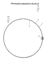
- Figures 1,2 and 3 illustrate respectively the facade, the vertical section and the plan of a tank constructed following the design of the invention;
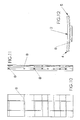
- Figures 4,5,6 and 7 illustrate respectively the lateral and frontal views, the vertical section and the plan of a block according to the invention;
- Figure 8 is a detail of the connection between two blocks;
- Figure 9 illustrates a detail of the panel;
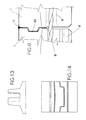
- Figures 10,11 and 12 illustrate respectively the frontal view, the lateral view and the plan of the terminal block of the tank;
- Figures 13 and 14 are the lateral view and the plan of a plinth for the positioning of the terminal block;
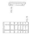
- Figures 15 and 16 show a general view and a detail of a further more popular version according to the invention.
- With reference to Figures 1 and 3, a tank out of the ground is created by the combination of a number of blocks and panels (1), joined and fixed at their extremities to a head element (2) which is mounted on a foundation plinth (3).
- Each of these blocks has an arc cross-section (Fig. 7) viewed from above and has the
sides - A characteristic of the invention is that each of these blocks has a series of essentially horizontal ribbing, illustrated in detail in Figure 9.
- The ribbing (6) creates a raised border or parapet (7) on the external part of the block thus forming a seating between the wall of the panel and this border for the tension cables (8). The upper wall (9) of each rib is not flat but is raised in the centre so that the bottom of ribbing slopes from the centre outwards.
- The ribbing (6) is slightly shorter than the panel itself so as to leave a small space between adjacent ribbing when construction is complete, as shown in Fig. 8. The distance between the ribbing is not constant. Lower down on the panel the ribs are closer together, where the hydrostatic pressure exerted on the walls is greater and where the cables around the panels must thus be closer together. By cutting blocks off at the base, one can obtain tanks of different heights.
- The head element (2) (Figs. 10,11 and 12) also has an arc plan cross-section. but without ribbing. It is thicker than the other blocks, essentially equal to the thickness of the panels (1) plus that of the ribbing, with the central part enlarged to contain the ends of the cables (8) to be tightened, giving a firm anchorage.
- The head element (2) is mounted on a plinth (10) with a seating (11) shaped to allow (1) the insertion and fastening of the element (2).
- For the assembly of the tank, a foundation kerb and plate are set out, on which the various blocks are placed. The plinth is then put in position and the head element assembled, fixing it temporarily with two wedges or similar objects.
- The various blocks are then put in place side by side bringing the lateral walls together and fixing them, again temporarily, with a gusset plate, a clamp or similar system, with the first and the last block fixed to the head (2).
- During assembly a sealing gasket (10) (Fig. 8) is placed between adjacent blocks, made of Neoprene or similar material.
- At this point the tension cables can be put in place. They are simply inserted in the ribbed seatings (6) with the respective borders (7) and anchored at their ends to the head element (2).
- This operation is made easier by the fact that the cables only have to be laid on the ribbing. They are thus already exactly positoned for tightening without having to use support elements or having to check and make adjustments to their positon.
- Once the cables have been tightened and anchored the gusset plates which held the blocks together can be removed and finishing operations carried out - e.g. applying a layer of sealing glue (11) along the internal edges of the blocks (Fig. 8), filling the seatings with mortar or similar material thus protecting the cables from possible damage and from atmospheric weathering.
- If, on the other hand, the space around the cables is not filled, then the sloping of the bottom wall (9) of the seating makes for rapid drainage of water which is deposited on the outside through the space left free between the ribbing. If particularly rigid panels are requested then vertical ribbing (12) (Fig. 15) can be provided in the external wall with holes through which cables may pass.
- The advantages of these newly-invented products are various. During production it is possible to make blocks of varying heights using the same caisson, simply by inserting partitions.
- Assembly is much simpler and more practical. It is not necessary to use bracing elements for the temporary attachment of the panels and it is enough to just place the cables in the seating which then position themselves exactly on tightening.
- Water drainage is improved in the cable seating area, which can also be protected with a filling of mortar or other suitable material.
- Finally, the appearance of the tank is improved with the cables hidden from sight.
- Experts in the sector may foresee any number of modifications and variations which must, however, be held to be included in the scope of the present invention.
Claims (11)
- Method for the creation of circular tanks, characterized by the following phases:- positioning of a foundation plinth and a head block for the attachment of the tension cables;- positioning of a series of blocks or panels for the construction of the walls of the tank, fixing them with temporary, removable means and with these panels providing seating on the external surface for tension cables;- positioning of tension cables in the said seating;- the tightening of these cables and their attachment to the head block;- the removal of the temporary connection devices between the panels;
- Manufactured parts for constructing circular tanks out of the ground, made of blocks with an arc plan cross-section and external ribbing for tension cable seating.
- Manufactured parts as described in claim 2, in which said ribbing has a raised external edge, the height of which is greater than the diameter of the cable.
- Manufactured parts as described in claim 3, in which said ribbing is shaped into a channel.
- Manufactured parts as described in claims 2 and 4, in which the said seatings for the cables are sloping, with an open section at the end for water drainage.
- Manufactured parts as described in claim 5 in which open sections are formed by making the length of the ribbing slightly less than the width of the panel.
- Manufactured parts as described in any of the claims from 2 to 6, in which the distance between the ribbings varies vertically on the panel, being closer together lower down, where there is greater hydrostatic pressure.
- Manufactured parts as described in any of the claims from 1 to 7, in which there are also vertical ribs to increase rigidity, the ribbing having holes through which the cables which lodge in the channels may pass.
- Tanks made with manufactured parts as described in claims 2 to 8.
- Tanks as in claim 9, with a band of flexible sealing material inserted between adjacent panels.
- Prefabricated circular tanks made by the method described in claim 1.
Applications Claiming Priority (2)
| Application Number | Priority Date | Filing Date | Title |
|---|---|---|---|
| IT04480990A IT1247587B (en) | 1990-04-18 | 1990-04-18 | MANUFACTURES AND METHOD FOR THE CREATION OF CIRCULAR TANKS. |
| IT4480990 | 1990-04-18 |
Publications (1)
| Publication Number | Publication Date |
|---|---|
| EP0452537A1 true EP0452537A1 (en) | 1991-10-23 |
Family
ID=11256439
Family Applications (1)
| Application Number | Title | Priority Date | Filing Date |
|---|---|---|---|
| EP90114841A Withdrawn EP0452537A1 (en) | 1990-04-18 | 1990-08-02 | Manufactured parts and method for the realization of circular tanks |
Country Status (2)
| Country | Link |
|---|---|
| EP (1) | EP0452537A1 (en) |
| IT (1) | IT1247587B (en) |
Cited By (6)
| Publication number | Priority date | Publication date | Assignee | Title |
|---|---|---|---|---|
| ES2084554A2 (en) * | 1993-10-26 | 1996-05-01 | Prefabricats M Planas S A | Hollow structure formed by prefabricated concrete panels and process for manufacturing said structure |
| WO2001051740A1 (en) * | 2000-01-10 | 2001-07-19 | Abetong Teknik Ab | Casting of tank |
| ES2212887A1 (en) * | 2002-05-17 | 2004-08-01 | Francisco J. Segovia Espiau | Method for obtaining drum-shaped high capacity tanks to store liquid, involves arranging polyhedron segments in parallel to axis of shell, where circular surfaces are contained in two planes, which are formed perpendicular to axis of shell |
| JP2012233354A (en) * | 2011-05-02 | 2012-11-29 | Ihi Corp | Low-temperature tank |
| WO2022226573A1 (en) * | 2021-04-28 | 2022-11-03 | Concept Environmental Services Pty Ltd | Brine processing system |
| US11885224B2 (en) * | 2008-01-28 | 2024-01-30 | Darin R. Kruse | Apparatus and methods for underground structures and construction thereof |
Families Citing this family (1)
| Publication number | Priority date | Publication date | Assignee | Title |
|---|---|---|---|---|
| CN113734640A (en) * | 2021-09-06 | 2021-12-03 | 华电重工股份有限公司 | Steel plate bin |
Citations (5)
| Publication number | Priority date | Publication date | Assignee | Title |
|---|---|---|---|---|
| GB1103455A (en) * | 1965-06-08 | 1968-02-14 | Preload International Inc | Prestressed steel tank structure |
| AT302921B (en) * | 1970-10-12 | 1972-11-10 | Friedrich Oestreicher Ing | Container, shaft or the like., In particular for sewage systems and apparatus for producing plates for such a container |
| GB1306448A (en) * | 1969-08-05 | 1973-02-14 | Leon Ballot Sa Des Entreprises | Reservoirs |
| DE3004473A1 (en) * | 1979-02-10 | 1980-08-21 | Betonson B V | Cylindrical tank wall building method - uses variably shaped concrete blocks with reinforcement cables tensioned and cemented into longitudinal channels |
| DE8608882U1 (en) * | 1986-04-03 | 1986-05-15 | Dyckerhoff & Widmann AG, 81902 München | Set of components for producing the wall of an upright container, in particular a liquid manure container |
-
1990
- 1990-04-18 IT IT04480990A patent/IT1247587B/en active IP Right Grant
- 1990-08-02 EP EP90114841A patent/EP0452537A1/en not_active Withdrawn
Patent Citations (5)
| Publication number | Priority date | Publication date | Assignee | Title |
|---|---|---|---|---|
| GB1103455A (en) * | 1965-06-08 | 1968-02-14 | Preload International Inc | Prestressed steel tank structure |
| GB1306448A (en) * | 1969-08-05 | 1973-02-14 | Leon Ballot Sa Des Entreprises | Reservoirs |
| AT302921B (en) * | 1970-10-12 | 1972-11-10 | Friedrich Oestreicher Ing | Container, shaft or the like., In particular for sewage systems and apparatus for producing plates for such a container |
| DE3004473A1 (en) * | 1979-02-10 | 1980-08-21 | Betonson B V | Cylindrical tank wall building method - uses variably shaped concrete blocks with reinforcement cables tensioned and cemented into longitudinal channels |
| DE8608882U1 (en) * | 1986-04-03 | 1986-05-15 | Dyckerhoff & Widmann AG, 81902 München | Set of components for producing the wall of an upright container, in particular a liquid manure container |
Cited By (7)
| Publication number | Priority date | Publication date | Assignee | Title |
|---|---|---|---|---|
| ES2084554A2 (en) * | 1993-10-26 | 1996-05-01 | Prefabricats M Planas S A | Hollow structure formed by prefabricated concrete panels and process for manufacturing said structure |
| WO2001051740A1 (en) * | 2000-01-10 | 2001-07-19 | Abetong Teknik Ab | Casting of tank |
| AU778554B2 (en) * | 2000-01-10 | 2004-12-09 | Abetong Teknik Ab | Casting of tank |
| ES2212887A1 (en) * | 2002-05-17 | 2004-08-01 | Francisco J. Segovia Espiau | Method for obtaining drum-shaped high capacity tanks to store liquid, involves arranging polyhedron segments in parallel to axis of shell, where circular surfaces are contained in two planes, which are formed perpendicular to axis of shell |
| US11885224B2 (en) * | 2008-01-28 | 2024-01-30 | Darin R. Kruse | Apparatus and methods for underground structures and construction thereof |
| JP2012233354A (en) * | 2011-05-02 | 2012-11-29 | Ihi Corp | Low-temperature tank |
| WO2022226573A1 (en) * | 2021-04-28 | 2022-11-03 | Concept Environmental Services Pty Ltd | Brine processing system |
Also Published As
| Publication number | Publication date |
|---|---|
| IT9044809A0 (en) | 1990-04-18 |
| IT9044809A1 (en) | 1991-10-18 |
| IT1247587B (en) | 1994-12-28 |
Similar Documents
| Publication | Publication Date | Title |
|---|---|---|
| US4328651A (en) | Precast concrete constructions | |
| CA2601457C (en) | Concrete panel construction system | |
| US3316721A (en) | Tensioned retaining wall for embankment | |
| US4090266A (en) | Swimming pool construction | |
| US6568141B2 (en) | Concrete footing and wall system | |
| EP0803618A2 (en) | Modular element for the support and ventilation of floors | |
| EP0185065B1 (en) | Method for making a rigid slab able to support a building | |
| US5540524A (en) | Concrete slab foundation and method of construction | |
| US5067289A (en) | Foundation system for manufactured housing | |
| WO2002018712A1 (en) | Integrated footings | |
| EP0452537A1 (en) | Manufactured parts and method for the realization of circular tanks | |
| CA1145584A (en) | Concrete form system | |
| US6192639B1 (en) | Structural system for erecting buildings, particularly single-family dwellings | |
| US4697398A (en) | Multistoried aseismic building made of modular panels | |
| US4811536A (en) | Outer wall structure for buildings | |
| US20050183363A1 (en) | Prefabricated tower foundation comprising equipment shelters and a method for its deployment on site | |
| AU707066B2 (en) | Fluid circulation pipe | |
| US6477722B2 (en) | Overflow system with a spillway rim, particularly for a prefabricated swimming pool to be sunk into the ground, and a method and apparatus for its construction | |
| EP0107749A1 (en) | Aseismatic building structure | |
| EP1208270B1 (en) | Foundation and method for its production | |
| US3834094A (en) | Track system wall assembly for houses or the like | |
| US20070079567A1 (en) | Grid system for building structure and method therefor | |
| WO1997043499A1 (en) | Interlocking building block | |
| GB2268525A (en) | Water-tight building structures | |
| JPH0730755Y2 (en) | Retaining wall block |
Legal Events
| Date | Code | Title | Description |
|---|---|---|---|
| PUAI | Public reference made under article 153(3) epc to a published international application that has entered the european phase |
Free format text: ORIGINAL CODE: 0009012 |
|
| AK | Designated contracting states |
Kind code of ref document: A1 Designated state(s): AT BE CH DE ES FR GB GR LI LU NL |
|
| 17P | Request for examination filed |
Effective date: 19920326 |
|
| 17Q | First examination report despatched |
Effective date: 19930609 |
|
| STAA | Information on the status of an ep patent application or granted ep patent |
Free format text: STATUS: THE APPLICATION IS DEEMED TO BE WITHDRAWN |
|
| 18D | Application deemed to be withdrawn |
Effective date: 19931020 |