EP0452498B1 - Imaging apparatus - Google Patents
Imaging apparatus Download PDFInfo
- Publication number
- EP0452498B1 EP0452498B1 EP90914764A EP90914764A EP0452498B1 EP 0452498 B1 EP0452498 B1 EP 0452498B1 EP 90914764 A EP90914764 A EP 90914764A EP 90914764 A EP90914764 A EP 90914764A EP 0452498 B1 EP0452498 B1 EP 0452498B1
- Authority
- EP
- European Patent Office
- Prior art keywords
- ink
- layer
- ink sheet
- powder
- sheet
- Prior art date
- Legal status (The legal status is an assumption and is not a legal conclusion. Google has not performed a legal analysis and makes no representation as to the accuracy of the status listed.)
- Expired - Lifetime
Links
Images


Classifications
-
- B—PERFORMING OPERATIONS; TRANSPORTING
- B82—NANOTECHNOLOGY
- B82Y—SPECIFIC USES OR APPLICATIONS OF NANOSTRUCTURES; MEASUREMENT OR ANALYSIS OF NANOSTRUCTURES; MANUFACTURE OR TREATMENT OF NANOSTRUCTURES
- B82Y15/00—Nanotechnology for interacting, sensing or actuating, e.g. quantum dots as markers in protein assays or molecular motors
-
- B—PERFORMING OPERATIONS; TRANSPORTING
- B41—PRINTING; LINING MACHINES; TYPEWRITERS; STAMPS
- B41J—TYPEWRITERS; SELECTIVE PRINTING MECHANISMS, i.e. MECHANISMS PRINTING OTHERWISE THAN FROM A FORME; CORRECTION OF TYPOGRAPHICAL ERRORS
- B41J31/00—Ink ribbons; Renovating or testing ink ribbons
- B41J31/14—Renovating or testing ink ribbons
Definitions
- the present invention relates to image formation devices which use a thermal head and an ink sheet with an ink layer on a base film and which form images by energizing the thermal head and using the heat of the thermal head to transfer the ink layer of the ink sheet to the recording paper (referred to as thermal transfer below), and more particularly to thermal transfer type image formation devices equipped with a regeneration mechanism for the ink sheet.
- Some of the recording methods being used as thermal transfer methods include melt transfer recording and sublimal-dye transfer recording, which have been used to realize compact, highly reliable image formation devices.
- the method disclosed in USP-4467332 is a regeneration method which uses an ink sheet configured from an ink layer formed on a conductive base film and selectively supplies insulative powder ink to conductive exposed parts after transfer of the ink layer, but since the chargeability of the insulative powder ink varies depending on the environment, the film thickness is not consistent and powder ink adheres to even untransferred parts of the ink layer according to the strength of the electric field. In other words, it is difficult to selectively adhere powder ink to transferred parts of the ink layer, and uneven adherence of the powder ink occurs. Therefore, it is difficult to control the film thickness of the ink layer of the regenerated ink sheet, thus resulting in an uneven ink layer.
- the purpose of the present invention is to go beyond that disclosed in Japanese Laid-Open Patent Publication 1-295876 by offering an image formation device which more effectively utilises the ink sheet and greatly reduces running costs.
- Another purpose of the invention is to offer an image formation device with a mechanism for ink sheet regeneration capable of easily accommodating colour printing.
- an image formation device for forming images by means of a thermal transfer system and an ink sheet, said device comprising an ink sheet regeneration mans for regenerating the ink sheet sequentially with the image formation, characterised in that said ink sheet regeneration means includes means for supplying photoconductive powder ink to said ink sheet; means for irradiating the powder ink through the ink sheet to adhere the powder ink to parts of the ink sheet without ink; and means for fixing the powder ink on the ink sheet.
- photoconductive powder ink used in the image formation device of the invention.
- good regeneration could be performed with materials and configurations such as those described below.
- they include photoconductive materials, sensitizers, resins which bind photoconductive materials, resins for fixing and colorants.
- Photoconductive materials refer to those materials which demonstrate the following properties.
- Such materials are produced by mixing and diffusing a binding resin with a dye or pigment or coating only a resin and forming it into a film, and they demonstrate a light-attenuation of their surface potential, or so-called "xero graphic" characteristic, when charged in darkness and then irradiated with light.
- the photosensitive materials used in copiers are examples of such materials. More specifically, these include such inorganic pigments as zinc oxide, titanium oxide, zinc sulfide, selenium, cadmium sulfide and a-silicon, such organic pigments as phthalocyanine and quinacridone and such resin materials as carbazole resins.
- Sensitizers are selected to increase the sensitivity of photoconductive materials and to select the photosensitive wavelength range, and they include triphenylmethane dyes, diallylmethane dyes, monomethine cyanine, trimethine cyanine, pentamethine cyanine, heptamethine cyanine, styryl dyes, oxanal, merocyanine, cyanine complexes, azenium dyes, azo dyes, anthraquinone dyes, indigo dyes, vinylene dyes and azomethines. Examples of these types of dyes include Rose Bengal, acridine orange, rhodamine B, erythrosine, eosin, fluorescein, brilliant Green and crystal violet.
- nigrosine dye aniline blue, chalco oil blue, chrome yellow, ultramarine blue, Dupont oil red, quinoline yellow, methylene blue colloid, phthalocyanine blue, Malachite Green oxalate, lampblack, oil black, azo oil black, Rose Bengal, crystal violet and Rhodamine B.
- Known insulative thermoplastic resins can be used as resins for binding photoconductive materials, and some of those that can be used alone or in combination include polyacrylates, polymethacrylates and other acrylic resins and their copolymers, polystyrene, poly-1-methylstyrene and other styrene resins and their copolymers, polyvinyl colloids, polyvinylidene colloids, polyvinyl fluorides, polyvinylidene fluorides and polyester resins and their copolymers, and polycarbonate resins, cellulose resins and polyarylate resins.
- the following low-melting point compounds can be used as inner core particles for fixing: candelilla wax, carnauba wax, rice wax, beeswax, lanolin, montan wax, ozokerite, paraffin wax, microcrystalline wax, petrolatum, polyethylene wax, Fischer-Tropsch synthetic wax, montan wax derivative, paraffin wax derivative, hardened castor oil, synthetic waxes and other waxes, stearic acid, palmitic acid and other higher fatty acids, low molecular weight polyethylenes, polyethylene oxides, polypropylenes and other polyolefines, and ethylenes, acrylic acid ccpolymers, ethylene-ester acrylate copolymers, ethene-vinyl acetate copolymers and other olefine copolymers.
- an ink layer is laminated on a base layer which also serves as a dielectric layer, and as shown in FIG. 1, an ink sheet is used in which a transparent or translucent conductive layer is provided on the side toward the irradiated light and opposite the ink layer of the base layer, but the invention is not limited to this, and it includes all ink sheets which have at least a dielectric layer and an ink layer formed on the dielectric layer as their primary components.
- the base layer which also serves as a dielectric layer, should be an insulative material that is transparent or translucent with respect to the irradiated light, and more specifically it is a film made from simple substances, copolymers, or composites of resins selected from among such organic films as polyesters, polysulfones, polyimides, polyamides, polyaramides, polycarbonates and other organic films or from among such thermoplastic resins as polyvinyl alcohols, polyvinyl pyrrolidones, polyvinyl amines, gum arabic, polyglutamic acid, polyvinyl colloids, polycarbonates, polyvinyl butyral, polystyrenes, polyacrylates, polyesters and cellulose resins, from resins selected from among such thermosetting resins as epoxy resins, silicon resins, urethane resins, melamine resins and alkyd resins, or from nitrides, oxides, carbides and inorganic salts. More desirably, the film should be a heat resistant
- the conductive layer can be formed from a conductive resin by diffusing and dissolving a conductive agent in a known binder resin, or from a conductive agent alone.
- conductive agents that can be used include metal oxide powders, metal powders and salts.
- FIG. 1 is a generalized diagram of the regeneration mechanism of the image formation device of the invention.
- similar component parts are designated by the same numbers.
- the ink sheet 1 is a take-up cartridge system, and it Comprises a photoconductive ink layer 2 on an insulator layer 3 and a transparent conductive layer 4 on the opposite side.
- the ink sheet wound up in the cartridge is transported in the direction of the arrow 8.
- the ink sheet 1 On the ink sheet 1 are formed areas 5 where the photoconductive ink layer 2 has been transferred and separated from the ink sheet by the printing operation leaving the insulator layer 3 bare and areas 6 where the photoconductive ink layer 2 remains untransferred.
- the powder ink 7 made from nearly the same components as the photoconductive ink layer is stored in the two-component hopper 9, and it attains a negative charge through frictional electrification.
- the photoconductive powder ink adheres to the sleeve in a thin layer due to electrostatic force when it comes in contact with the sleeve.
- the ink layer of the ink sheet is regenerated by a fixing means 14 which fixes the powder ink 7 on the photoconductive ink sheet by means of a heat roller or heat-pressure roller (a heat roller is used as the fixing means in FIG. 1), and the ink sheet is wound up in the cartridge.
- the fixing means is not limited to the rollers noted above; i.e., other means can be used such as a flash fixing means or a means which holds the base film and melts the ink from the opposite side of the ink layer by means of a heat plate.
- a 4-»m-thick polyester film can be used as the insulator layer 3 of the ink sheet 1, indium-tin oxide (ITO below) can be used as the transparent conductive layer 4, and a microcapsule-type ink produced by the method described below and coated with heat and pressure can be used as the photoconductive ink layer.
- ITO indium-tin oxide
- a microcapsule-type ink produced by the method described below and coated with heat and pressure can be used as the photoconductive ink layer.
- the method by which the microcapsule ink is produced is not limited to the method described here.
- carnauba particles with a particle diameter of 8 »m are dyed directly in an alcohol solution of black dye-1 and used as the inner core particles.
- Zinc oxide 75 parts by weight Cyanine dye 0.075 parts by weight Ethyl alcohol 100 parts by weight Butyryl resin 75 parts by weight
- a cyanine dye with the following structure was used as a sensitizer.
- the above materials are mixed, evenly dispersed by ultrasonic waves and then adsorbed.
- the resin is then added to this dispersed solution and dispersed in the same manner by ultrasonic waves, whereby a zinc oxide-dispersed resin is produced.
- the inner core particles are then added to this resin solution and evenly dispersed by ultrasonic waves.
- the stock solution is produced so its solid portion is 20 percent, and the photoconductive powder ink, which has been surface-coated by a spray-dry method, is produced. Examination by electron microscope showed that the zinc oxide-dispersed film had been coated to a thickness of approximately 1 »m.
- FIG. 3 A generalized cross section of the microcapsule-type photoconductive powder ink produced in this embodiment is shown in FIG. 3.
- the outer shell photosensitive layer 21 of microcapsule-type photoconductive powder ink is not limited to a pigment-dispersed type as in this embodiment, but it may have any type of composition, such as only a pigment or resin, as long as it has photoconductivity.
- An ink sheet 1 which has been used to form an image and is regenerated in this manner can be used to form images again.
- the support member 3 should be heat resistant and be easily formed into a film (e.g., polyester, polysulfone, polyimide, polyaramide).
- the powder ink 7 may be in the form of fine particles, paste, melted or dissolved, or partially melted or dissolved, but the most desirable is fine particles. (A fine particle ink is used in FIG. 1.)
- a printing test was performed using the process of the first embodiment. Since a cyanine dye sensitive to the near infrared range was used as the sensitizing dye, an exposure device which passes light in the near infrared range was employed as the light source.
- the conditions under which the test was performed were a charge of -10 »C/g for the photoconductive powder ink and an impressed bias of +500 V on the conductive sleeve.
- a printing speed of 20 pages per minute was obtained at 32 gradations.
- the images produced had an OD value between 1.2 and 1.5, and good reproducibility was obtained in a 10 000-cycle printing test.
- Writing was performed at this time at a luminous energy of approximately 10 erg/cm2 on the sleeve of the exposure system.
- FIG. 2 is a generalized diagram of a color image formation device. The following explanation of the process of the invention is based on FIG. 2. In the figure, the same components as in the first embodiment are designated by the same numbers.
- Color printing is performed using a cartridge system which sequentially feeds parts divided into each of the colors yellow, magenta and cyan (designated below as Y, M and C, respectively) as the ink sheet.
- compositions of each of the color photoconductive powder inks are as follows.
- Basic composition Inner core resin carnauba wax spheres
- Colorant Photoconductive agent zinc oxide Sensitizing dye Outer shell binding resin butyryl resin
- the colorants and sensitizers in each of the color powder inks are as follows. Cyan powder ink Colorant copper phthalocyanine Sensitizers NK1870, phthalic anhydride Magenta powder ink Colorant quinacridone Sensitizers tetrabromophenol blue, phthalic anhydride Yellow powder ink Colorant disazo dye Sensitizers Rose Bengal, phthalic anhydride
- the carnauba wax and each of the colorants are kneaded together and powdered, which is then used as the inner core particles.
- the above materials except for the inner resin are mixed, evenly dispersed by ultrasonic waves and adsorbed.
- a zinc oxide-dispersed resin solution is prepared by adding resin to this dispersion solution and then dispersing the solution with ultrasonic waves in the same manner.
- the inner core particles are then added to the resin solution and evenly dispersed with ultrasonic waves.
- the stock solution is produced so its solid portion is 20 percent, and the color powder inks which have been surface-coated by a spray-dry method are produced with a spherically shaped particle diameter of 10 »m. Examination by electron microscope showed that the zinc oxide-dispersed film is coated in a thickness of approximately 1 »m.
- the inks are supplied and used to regenerate by the following method. First, they are electrified by friction while being mixed in the two-component hopper 9 and then they are formed in a thin layer on the conductive sleeve 10. Next, the ink sheet divided up into each of the colors is supplied over the hoppers corresponding to each of the colors with photoconductive powder ink to those parts of the ink layer transferred by printing and then it is regenerated.
- the photoconductive powder ink is supplied by exposing the entire surface to blue light in the case of regeneration of the cyan ink layer and adhering the cyan powder ink in a single layer.
- the ink sheet is then levelled by heat and pressure. All three parts of the ink sheet are regenerated in the same manner.
- An ink sheet 1 which has been used to form an image and is regenerated in this manner can be used to form images again.
- That part of the powder ink 7 supplied by the conductive sleeve 10 to the ink sheet 1 which comes in contact with areas 5 where the photoconductive ink layer 2 has been transferred and separated from the ink sheet 1 leaving the insulator layer 3 bare is made conductive by full-surface exposure to light from the light source 13 and receives a charge injection, thus causing it to adhere to the areas 5.
- the untransferred areas 6, which are of the same composition as the ink layer 2 absorb and disperse the light to which they are exposed, the powder ink 7 which comes in contact with the untransferred areas 6 continues to be transported while retaining its initial charge and is bound by the electrostatic force with the sleeve.
- the ink layer retains its resistance while in darkness without exciting a photoconductive effect and its sensitizer is broken down by selecting the heat and pressure operating conditions during production of the sheet, and therefore the image force between charged particles is small, thus preventing the powder ink from adhering to the ink layer. In this manner, the supply of powder ink 7 can be restricted to only the transferred parts of the photoconductive ink layer 2.
- the ink layer of the ink sheet is regenerated by a fixing means 14 which fixes the powder ink 7 on the photoconductive ink sheet by means of a heat roller or heat pressure roller (a heat roller is used as the fixing means in FIG. 1), and the ink sheet is wound up in the cartridge.
- a fixing means 14 which fixes the powder ink 7 on the photoconductive ink sheet by means of a heat roller or heat pressure roller (a heat roller is used as the fixing means in FIG. 1), and the ink sheet is wound up in the cartridge.
- Color printing was performed using the process in the fourth embodiment.
- the device used is nearly the same as that in the second embodiment.
- One of the above three color powder inks is provided at the ink regeneration means 15. Another one of the color powder inks is provided at the generation means 16. The remaining one color powder ink is provided at the generation means 17.
- the inks are supplied and used to regenerate by the following method.
- the ink sheet divided up into each of the colors is supplied over the hoppers corresponding to each of the colors with photoconductive powder ink to those parts of the ink layer transferred by printing and then is regenerated.
- the photoconductive powder ink is supplied by exposing the entire surface to blue light in the case of regeneration of the cyan ink layer and adhering the cyan powder ink in a single layer.
- the photoconductive ink is then fixed by heat rolling at a fixing temperature of 150°C to level the ink sheet. All three colors of the ink sheet are regenerated in the same manner.
- An ink sheet 1 which has been used to form an image and is regenerated in this manner can be used to form images again. No change in resistance was observed at this time when the ink sheet was irradiated with light corresponding to the colors. This indicates that the sensitizing dye (e.g., NK1870 in the case of cyan ink) is broken down by the means for fixing the photoconductive powder ink on the ink sheet, thus losing its sensitivity.
- the sensitizing dye e.g., NK1870 in the case of cyan ink
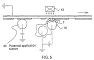
- FIG. 5 is a generalized diagram of this process.
- the potential application mechanism uses a conductive sleeve here, but it is not limited to this, in that a conductive brush, corona discharge device, etc., can be used.
- photoconductive powder ink can be selectively supplied according to the wavelength of the light, color printing can be accommodated with only one powder ink hopper.
- the three color powder inks Y, M and C randomly formed in a thin film on the conductive sleeve are supplied to the ink sheet.
- the powder ink which comes in contact with the areas 5 where the photoconductive ink layer 2 has been transferred and separated from the ink sheet leaving the insulator layer 3 bare is fully exposed to blue light in the case of regeneration of the cyan ink layer, for example, and the cyan powder ink is adhered in a single layer.
- the powder ink 7 which comes in contact with the untransferred parts 6 is not irradiated by the light because the cyan ink layer absorbs and diffuses the exposed blue light, it retains its initial charge and is transported on the conductive sleeve 10 by the electrostatic force. In this way, the supply of powder ink 7 can be restricted to only the transferred parts of the photoconductive ink layer 2.
- the color ink sheet is then regenerated in the same manner as in the second embodiment.
- a thin layer on the conductive sleeve is used to replenish the ink layer made up of photoconductive powder ink, but it is possible to use a two-component mix of particles made from a magnetic ferrite or iron powder material and a powder ink formed as a brush on a magnetic sleeve to replenish the ink layer directly.
- FIG. 6 shows an example of this.
- a slit that is narrower than the contact surface (nip width) between the magnetic brush and the ink layer is provided and light is passed through it.
- the remainder of the method is the same as in the first configuration. This prevents the splashing of powder ink and yields good print quality with good reproducibility.
- an air gap may form which reduces the effective adhesion electric field to which the powder ink is subjected or the conductive path may occasionally form and disappear, and therefore it is important achieve uniform contact in order to achieve uniform adhesion.
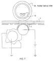
- FIG. 7 shows a generalized diagram of the process of an image formation device in which uniform contact is attempted using the photoconductive powder ink of the invention.
- the basic configuration is the same as that of the first embodiment.
- a transparent acrylic rubber is used for the rubber backup roller 25, and the surface is coated with silicon by a spray method in order to achieve sufficient smoothness.
- the transparent elastic body used has a JIS hardness of 30° and a transmissivity of 95%, and the nip width when set against the opposing member is approximately 2 mm.
- the photoconductive powder ink frictionally electrified by the two-component magnetic brush is formed in a thin layer on the conductive sleeve 10 according to the strength of the electric field.
- This photoconductive powder ink formed in a thin layer is used to form the image by pressing the conductive sleeve 2 and the roller against each other, impressing an electric field between the two and irradiating the ink with light from the exposure system 13.
- the contact pressure condition during supply is depicted in FIG. 8. Reverse charge injection does not occur since point contact with the supply sleeve is maintained.
- a low-cost semiconductor laser can be used as the light source for the exposure system since near infrared sensitivity is increased by using zinc oxide as the sensitizing dye. Only the powder ink irradiated by light and made conductive is injected with a charge and forms a single layer on the dielectric surface. Next, the powder ink is fixed by heating with a heat roller.
- Transparent rubber is used in the contact pressure system of this embodiment, but actual devices are not limited to this; i.e., a spring system, air damper system or a combination of these can also be used.
- the photoconductive powder ink is produced using zinc oxide as in the first embodiment, and the process was tested using various types of transparent elastic bodies.
- Table 1 shows the relationship of print quality to the elastic body material and the JIS hardness.
- the hardness is greater than 50°, the amount supplied is small, which reduces printing density and results in the appearance of background.
- contact is not uniform, resulting in much dropout.
- the process employing the elastic body of the invention can also be applied to color printing.
- a transparent acrylic rubber is used on the drum surface 9, and printing is performed with a device which uses a drum whose surface is coated with silicon by a spray method in order to achieve sufficient smoothness.
- the four color powder inks Y, M, C and Bk are provided at respective ink regeneration means 15, 16, 17 and 18 for each color and supply and regeneration are performed in the same manner as in the second embodiment.
- a printing speed of 5 pages per minute was obtained at 32 gradations.
- An OD value of greater than 1.5 was obtained for solid images, and good images were obtained with good reproducibility in a 10 000-cycle print test.
- Writing was performed at a luminous energy greater than 10 erg/cm2 in the exposure system. In this way, sharp color images were obtained with good reproducibility.
- the ink sheet used in the invention comprises a base film made from 4-»m-thick ITO/aramid, a dielectric layer made from (100 - X) wt% acrylic resin and X wt% ITO and coated on the side opposite the conductive layer in a thickness of 1 » and a photoconductive powder ink coated on top of that. Printing and regeneration were performed using this ink sheet in a thermal transfer-type image formation device.
- Table 3 shows the results of an investigation of the correlation of the supply condition of the powder ink and print quality to the resistivity of the dielectric layer.
- ⁇ is the resistivity ( ⁇ cm)
- A is the supply condition
- B is the print quality.
- the supply condition is shown as the ratio of adhered powder ink per unit of solid area expressed as a percentage, where "adheres in nearly single layer” indicates an adherence of 90 percent or better, “small amount adheres” indicates less than 10 percent adherence and “none adheres” indicates less than 1 percent adherence.
- An ink sheet is used with a base made from a non-deposition 4-»m-thick aramid film and on which a photoconductive powder ink is coated.
- Powder ink is supplied to the non-coated surface of the ink layer by pressing the ITO-deposited glass sleeve against the ink film.
- the light source is positioned inside the glass sleeve.
- the powder ink is supplied by subjecting the ink to a good charge injection via the electric field between the contact areas equivalent to the nip surface.
- the base film of the ink sheet used in the invention must be transparent or translucent to the light used for exposure, so experiments were performed with ink sheets of various transmissivities.
- PET polyethylene terephthalate
- the transmissivity was separately measured using a spectroscope, and print quality was evaluated using the same device and the same luminous energy as in the first embodiment and at a printing speed of 10 pages per minute.
- the image formation device of the invention has the following efficacies.
- an ink sheet regeneration process becomes possible which uses a powder ink containing no magnetic powder or carbon black, and therefore a thermal transfer type image formation device equipped with an ink sheet regeneration means can be offered which accommodates color printing and reduces running costs by increasing the utilization of the ink sheet.
- the image formation device of the invention can be particularly useful if applied to printers, video printers, facsimiles, copiers, etc.
Abstract
Description
- The present invention relates to image formation devices which use a thermal head and an ink sheet with an ink layer on a base film and which form images by energizing the thermal head and using the heat of the thermal head to transfer the ink layer of the ink sheet to the recording paper (referred to as thermal transfer below), and more particularly to thermal transfer type image formation devices equipped with a regeneration mechanism for the ink sheet.
- Some of the recording methods being used as thermal transfer methods include melt transfer recording and sublimal-dye transfer recording, which have been used to realize compact, highly reliable image formation devices.
- One example of a regeneration method for the ink sheet is that disclosed in the SID 1985 Digest, pages 143-145. The method disclosed in USP-4467332 is an ink sheet regeneration method which utilizes a powder ink. As a related technology, an ink sheet regeneration method and device were proposed in Japanese Laid Open Patent Publication 1-295876.
- In the method disclosed in the SID 1985 Digest, pages 143-145, however, a warm-up time is required to melt the ink, much power is required to melt the ink, a mechanism is required to obtain a fixed film thickness for the regeneration ink, the device is large and the mechanism is complicated.
- The method disclosed in USP-4467332 is a regeneration method which uses an ink sheet configured from an ink layer formed on a conductive base film and selectively supplies insulative powder ink to conductive exposed parts after transfer of the ink layer, but since the chargeability of the insulative powder ink varies depending on the environment, the film thickness is not consistent and powder ink adheres to even untransferred parts of the ink layer according to the strength of the electric field. In other words, it is difficult to selectively adhere powder ink to transferred parts of the ink layer, and uneven adherence of the powder ink occurs. Therefore, it is difficult to control the film thickness of the ink layer of the regenerated ink sheet, thus resulting in an uneven ink layer.
- However, the images formed using ink sheet prepared or regenerated by the ink sheet regeneration method and device disclosed in Japanese Laid-Open Patent Publication 1-295876 were high quality images with a high recording density (OD value below), and they also demonstrated a good repetitive characteristic.
- The purpose of the present invention is to go beyond that disclosed in Japanese Laid-Open Patent Publication 1-295876 by offering an image formation device which more effectively utilises the ink sheet and greatly reduces running costs. Another purpose of the invention is to offer an image formation device with a mechanism for ink sheet regeneration capable of easily accommodating colour printing.
- According to the present invention there is provided an image formation device for forming images by means of a thermal transfer system and an ink sheet, said device comprising an ink sheet regeneration mans for regenerating the ink sheet sequentially with the image formation, characterised in that said ink sheet regeneration means includes means for supplying photoconductive powder ink to said ink sheet;
means for irradiating the powder ink through the ink sheet to adhere the powder ink to parts of the ink sheet without ink; and
means for fixing the powder ink on the ink sheet. -
- FIG. 1 is a generalized diagram of the image formation device of an embodiment of the invention;
- FIG. 2 is a generalized diagram of the image formation device of another embodiment of the invention;
- FIG. 3 shows an example of the cross sectional structure of the photoconductive powder ink used in the invention;
- FIG. 4 shows the structure of the black dye used in the photoconductive powder ink of the invention;
- FIG. 5 shows an example of the voltage application mechanism of the invention;
- FIG. 6 shows the supply method of the invention which uses a two-component magnetic brush;
- FIG. 7 shows the supply method of the invention which uses an elastic backup roller; and
- FIG. 8 shows the contact pressure condition during supply when the elastic backup roller of the invention is used.
- 1
- ink sheet
- 7
- conductive powder ink
- 9
- two-component hopper
- 10
- conductive sleeve
- 13
- exposure system
- 18
- thermal head
- 19
- backup roller
- 20
- recording paper
- 23
- potential application sleeve
- 26
- rubber backup roller
- A detailed description of the invention follows.
- First is a detailed description of the photoconductive powder ink used in the image formation device of the invention. As a result of diligent research and study to achieve photoconductivity, it was discovered that good regeneration could be performed with materials and configurations such as those described below. Basically, they include photoconductive materials, sensitizers, resins which bind photoconductive materials, resins for fixing and colorants.
- Photoconductive materials refer to those materials which demonstrate the following properties.
- Such materials are produced by mixing and diffusing a binding resin with a dye or pigment or coating only a resin and forming it into a film, and they demonstrate a light-attenuation of their surface potential, or so-called "xero graphic" characteristic, when charged in darkness and then irradiated with light. The photosensitive materials used in copiers are examples of such materials. More specifically, these include such inorganic pigments as zinc oxide, titanium oxide, zinc sulfide, selenium, cadmium sulfide and a-silicon, such organic pigments as phthalocyanine and quinacridone and such resin materials as carbazole resins.
- Sensitizers are selected to increase the sensitivity of photoconductive materials and to select the photosensitive wavelength range, and they include triphenylmethane dyes, diallylmethane dyes, monomethine cyanine, trimethine cyanine, pentamethine cyanine, heptamethine cyanine, styryl dyes, oxanal, merocyanine, cyanine complexes, azenium dyes, azo dyes, anthraquinone dyes, indigo dyes, vinylene dyes and azomethines. Examples of these types of dyes include Rose Bengal, acridine orange, rhodamine B, erythrosine, eosin, fluorescein, brilliant Green and crystal violet.
- The following materials can be used as colorants: nigrosine dye, aniline blue, chalco oil blue, chrome yellow, ultramarine blue, Dupont oil red, quinoline yellow, methylene blue colloid, phthalocyanine blue, Malachite Green oxalate, lampblack, oil black, azo oil black, Rose Bengal, crystal violet and Rhodamine B.
- Known insulative thermoplastic resins can be used as resins for binding photoconductive materials, and some of those that can be used alone or in combination include polyacrylates, polymethacrylates and other acrylic resins and their copolymers, polystyrene, poly-1-methylstyrene and other styrene resins and their copolymers, polyvinyl colloids, polyvinylidene colloids, polyvinyl fluorides, polyvinylidene fluorides and polyester resins and their copolymers, and polycarbonate resins, cellulose resins and polyarylate resins.
- The following low-melting point compounds can be used as inner core particles for fixing: candelilla wax, carnauba wax, rice wax, beeswax, lanolin, montan wax, ozokerite, paraffin wax, microcrystalline wax, petrolatum, polyethylene wax, Fischer-Tropsch synthetic wax, montan wax derivative, paraffin wax derivative, hardened castor oil, synthetic waxes and other waxes, stearic acid, palmitic acid and other higher fatty acids, low molecular weight polyethylenes, polyethylene oxides, polypropylenes and other polyolefines, and ethylenes, acrylic acid ccpolymers, ethylene-ester acrylate copolymers, ethene-vinyl acetate copolymers and other olefine copolymers.
- Further, the following materials can be used as required.
- 1) Metal soap, polyethylene glycol and other surfactants or disperser
- 2) Electron acceptor organic complexes, polyester hydrochlorides, nitrohumic acid, quaternary ammonium salt, pyridinium salt and other charge control agents
- 3) Talc and other fillers
- 4) SiO₂, TiO₂ and other flowability enhancers.
- Next is a detailed explanation of the ink sheet of the invention. Structurally, an ink layer is laminated on a base layer which also serves as a dielectric layer, and as shown in FIG. 1, an ink sheet is used in which a transparent or translucent conductive layer is provided on the side toward the irradiated light and opposite the ink layer of the base layer, but the invention is not limited to this, and it includes all ink sheets which have at least a dielectric layer and an ink layer formed on the dielectric layer as their primary components.
- The base layer, which also serves as a dielectric layer, should be an insulative material that is transparent or translucent with respect to the irradiated light, and more specifically it is a film made from simple substances, copolymers, or composites of resins selected from among such organic films as polyesters, polysulfones, polyimides, polyamides, polyaramides, polycarbonates and other organic films or from among such thermoplastic resins as polyvinyl alcohols, polyvinyl pyrrolidones, polyvinyl amines, gum arabic, polyglutamic acid, polyvinyl colloids, polycarbonates, polyvinyl butyral, polystyrenes, polyacrylates, polyesters and cellulose resins, from resins selected from among such thermosetting resins as epoxy resins, silicon resins, urethane resins, melamine resins and alkyd resins, or from nitrides, oxides, carbides and inorganic salts. More desirably, the film should be a heat resistant, easy-to-form film made from polyesters, polysulfones, polyimides or polyaramides. A heat-resistant film can be added when a film with low heat resistance is used.
- The conductive layer can be formed from a conductive resin by diffusing and dissolving a conductive agent in a known binder resin, or from a conductive agent alone. Examples of conductive agents that can be used include metal oxide powders, metal powders and salts.
- Below are detailed explanations of the invention based on the drawings, and it goes without saying that the invention is not limited to these.
- Since the image formation part of the thermal transfer system uses known technology, the following explanations of the embodiments deal primarily with the ink sheet regeneration part.
- FIG. 1 is a generalized diagram of the regeneration mechanism of the image formation device of the invention. In the figures, similar component parts are designated by the same numbers.
- The
ink sheet 1 is a take-up cartridge system, and it Comprises a photoconductive ink layer 2 on aninsulator layer 3 and a transparentconductive layer 4 on the opposite side. - Upon completion of printing, the ink sheet wound up in the cartridge is transported in the direction of the
arrow 8. On theink sheet 1 are formedareas 5 where the photoconductive ink layer 2 has been transferred and separated from the ink sheet by the printing operation leaving theinsulator layer 3 bare andareas 6 where the photoconductive ink layer 2 remains untransferred. - The
powder ink 7 made from nearly the same components as the photoconductive ink layer is stored in the two-component hopper 9, and it attains a negative charge through frictional electrification. By impressing a positive bias on theconductive sleeve 10 which rotates in the direction of thearrow 11, the photoconductive powder ink adheres to the sleeve in a thin layer due to electrostatic force when it comes in contact with the sleeve. By grounding the transparentconductive layer 4 on the back of theink sheet 1 and impressing a positive bias voltage on theconductive sleeve 10, that part of thepowder ink 7 supplied to theink sheet 1 which comes in contact withareas 5 where the photoconductive ink layer 2 has been transferred and separated from theink sheet 1 leaving theinsulator layer 3 bare is made conductive by full-surface exposure to light from thelight source 13 and receives a charge injection from the sleeve, thus causing it to adhere to theareas 5. However, though theuntransferred areas 6, which are of the same composition as the ink layer 2, absorb and disperse the light to which they are exposed and the untransferred ink layer becomes conductive, thepowder ink 7 which comes in contact with theuntransferred areas 6 retains its initial charge because it itself is not irradiated by the light, and since a bias is impressed on the sleeve so it becomes positive, thepowder ink 7 is transported by electrostatic force on theconductive sleeve 10. In this way, the supply ofpowder ink 7 can be restricted to only the transferred parts of the photoconductive ink layer 2. - Next, the ink layer of the ink sheet is regenerated by a fixing means 14 which fixes the
powder ink 7 on the photoconductive ink sheet by means of a heat roller or heat-pressure roller (a heat roller is used as the fixing means in FIG. 1), and the ink sheet is wound up in the cartridge. The fixing means is not limited to the rollers noted above; i.e., other means can be used such as a flash fixing means or a means which holds the base film and melts the ink from the opposite side of the ink layer by means of a heat plate. - A 4-»m-thick polyester film can be used as the
insulator layer 3 of theink sheet 1, indium-tin oxide (ITO below) can be used as the transparentconductive layer 4, and a microcapsule-type ink produced by the method described below and coated with heat and pressure can be used as the photoconductive ink layer. The method by which the microcapsule ink is produced is not limited to the method described here. - First, carnauba particles with a particle diameter of 8 »m are dyed directly in an alcohol solution of black dye-1 and used as the inner core particles.
- Production of the solution is described below.
Zinc oxide 75 parts by weight Cyanine dye 0.075 parts by weight Ethyl alcohol 100 parts by weight Butyryl resin 75 parts by weight - A cyanine dye with the following structure was used as a sensitizer.

First, except for the inner resin, the above materials are mixed, evenly dispersed by ultrasonic waves and then adsorbed. - The resin is then added to this dispersed solution and dispersed in the same manner by ultrasonic waves, whereby a zinc oxide-dispersed resin is produced. The inner core particles are then added to this resin solution and evenly dispersed by ultrasonic waves. In this way, the stock solution is produced so its solid portion is 20 percent, and the photoconductive powder ink, which has been surface-coated by a spray-dry method, is produced. Examination by electron microscope showed that the zinc oxide-dispersed film had been coated to a thickness of approximately 1 »m.
- A generalized cross section of the microcapsule-type photoconductive powder ink produced in this embodiment is shown in FIG. 3. The outer shell
photosensitive layer 21 of microcapsule-type photoconductive powder ink is not limited to a pigment-dispersed type as in this embodiment, but it may have any type of composition, such as only a pigment or resin, as long as it has photoconductivity. - An
ink sheet 1 which has been used to form an image and is regenerated in this manner can be used to form images again. - Here, the
support member 3 should be heat resistant and be easily formed into a film (e.g., polyester, polysulfone, polyimide, polyaramide). Thepowder ink 7 may be in the form of fine particles, paste, melted or dissolved, or partially melted or dissolved, but the most desirable is fine particles. (A fine particle ink is used in FIG. 1.) - Using the photoconductive powder ink described above, a printing test was performed using the process of the first embodiment. Since a cyanine dye sensitive to the near infrared range was used as the sensitizing dye, an exposure device which passes light in the near infrared range was employed as the light source. The conditions under which the test was performed were a charge of -10 »C/g for the photoconductive powder ink and an impressed bias of +500 V on the conductive sleeve. When images were actually formed using this process, a printing speed of 20 pages per minute was obtained at 32 gradations. The images produced had an OD value between 1.2 and 1.5, and good reproducibility was obtained in a 10 000-cycle printing test. Writing was performed at this time at a luminous energy of approximately 10 erg/cm² on the sleeve of the exposure system.
- The process of the invention does not employ magnetic powder or carbon black, and therefore it is applicable to color printing. FIG. 2 is a generalized diagram of a color image formation device. The following explanation of the process of the invention is based on FIG. 2. In the figure, the same components as in the first embodiment are designated by the same numbers.
- Color printing is performed using a cartridge system which sequentially feeds parts divided into each of the colors yellow, magenta and cyan (designated below as Y, M and C, respectively) as the ink sheet.
- An ink sheet and photoconductive powder ink produced by the same methods as in the first embodiment are used.
- The compositions of each of the color photoconductive powder inks are as follows.
Basic composition Inner core resin carnauba wax spheres Colorant Photoconductive agent zinc oxide Sensitizing dye Outer shell binding resin butyryl resin - The colorants and sensitizers in each of the color powder inks are as follows.
Cyan powder ink Colorant copper phthalocyanine Sensitizers NK1870, phthalic anhydride Magenta powder ink Colorant quinacridone Sensitizers tetrabromophenol blue, phthalic anhydride Yellow powder ink Colorant disazo dye Sensitizers Rose Bengal, phthalic anhydride - First, the carnauba wax and each of the colorants are kneaded together and powdered, which is then used as the inner core particles.
- Next, the following solution is prepared.
Zinc oxide 75 parts by weight Sensitizing dye 0.075 parts by weight Ethyl alcohol 100 parts by weight Butyryl resin 75 parts by weight - First, the above materials except for the inner resin are mixed, evenly dispersed by ultrasonic waves and adsorbed.
- Next, a zinc oxide-dispersed resin solution is prepared by adding resin to this dispersion solution and then dispersing the solution with ultrasonic waves in the same manner. The inner core particles are then added to the resin solution and evenly dispersed with ultrasonic waves. In this way, the stock solution is produced so its solid portion is 20 percent, and the color powder inks which have been surface-coated by a spray-dry method are produced with a spherically shaped particle diameter of 10 »m. Examination by electron microscope showed that the zinc oxide-dispersed film is coated in a thickness of approximately 1 »m.
- One of the above three color powder inks is provided at the ink regeneration means 15. Another one of the color powder inks provided at the generation means 16. The remaining one color powder ink is provided at the generation means 17. The inks are supplied and used to regenerate by the following method. First, they are electrified by friction while being mixed in the two-
component hopper 9 and then they are formed in a thin layer on theconductive sleeve 10. Next, the ink sheet divided up into each of the colors is supplied over the hoppers corresponding to each of the colors with photoconductive powder ink to those parts of the ink layer transferred by printing and then it is regenerated. The photoconductive powder ink is supplied by exposing the entire surface to blue light in the case of regeneration of the cyan ink layer and adhering the cyan powder ink in a single layer. The ink sheet is then levelled by heat and pressure. All three parts of the ink sheet are regenerated in the same manner. - An
ink sheet 1 which has been used to form an image and is regenerated in this manner can be used to form images again. - When images were actually formed using this process, a printing speed of 20 pages per minute was obtained at 32 gradations. The images produced had an OD value between 1.2 and 1.5, and good reproducibility was obtained in a 10 000-cycle printing test. Writing was performed at this time at a luminous energy in the exposure system of approximately 10 to 20 erg/cm² for each color.
- Four-color printing was performed using the black photoconductive powder ink (Bk below) of the first embodiment. The system used was nearly the same as that in the second embodiment except that a hopper for black was added. When images were actually formed using this process, natural color reproduction was possible.
- In this embodiment, an image formation device based on another method of the invention is shown.
- That part of the
powder ink 7 supplied by theconductive sleeve 10 to theink sheet 1 which comes in contact withareas 5 where the photoconductive ink layer 2 has been transferred and separated from theink sheet 1 leaving theinsulator layer 3 bare is made conductive by full-surface exposure to light from thelight source 13 and receives a charge injection, thus causing it to adhere to theareas 5. However, since theuntransferred areas 6, which are of the same composition as the ink layer 2, absorb and disperse the light to which they are exposed, thepowder ink 7 which comes in contact with theuntransferred areas 6 continues to be transported while retaining its initial charge and is bound by the electrostatic force with the sleeve. The ink layer retains its resistance while in darkness without exciting a photoconductive effect and its sensitizer is broken down by selecting the heat and pressure operating conditions during production of the sheet, and therefore the image force between charged particles is small, thus preventing the powder ink from adhering to the ink layer. In this manner, the supply ofpowder ink 7 can be restricted to only the transferred parts of the photoconductive ink layer 2. - Next, the ink layer of the ink sheet is regenerated by a fixing means 14 which fixes the
powder ink 7 on the photoconductive ink sheet by means of a heat roller or heat pressure roller (a heat roller is used as the fixing means in FIG. 1), and the ink sheet is wound up in the cartridge. - Color printing was performed using the process in the fourth embodiment. The device used is nearly the same as that in the second embodiment.
- One of the above three color powder inks is provided at the ink regeneration means 15. Another one of the color powder inks is provided at the generation means 16. The remaining one color powder ink is provided at the generation means 17. The inks are supplied and used to regenerate by the following method.
- First, they are electrified by friction while being mixed in the two-
component hopper 9 and then formed in a thin layer on theconductive sleeve 10. Next, the ink sheet divided up into each of the colors is supplied over the hoppers corresponding to each of the colors with photoconductive powder ink to those parts of the ink layer transferred by printing and then is regenerated. The photoconductive powder ink is supplied by exposing the entire surface to blue light in the case of regeneration of the cyan ink layer and adhering the cyan powder ink in a single layer. The photoconductive ink is then fixed by heat rolling at a fixing temperature of 150°C to level the ink sheet. All three colors of the ink sheet are regenerated in the same manner. - An
ink sheet 1 which has been used to form an image and is regenerated in this manner can be used to form images again. No change in resistance was observed at this time when the ink sheet was irradiated with light corresponding to the colors. This indicates that the sensitizing dye (e.g., NK1870 in the case of cyan ink) is broken down by the means for fixing the photoconductive powder ink on the ink sheet, thus losing its sensitivity. - When images were actually formed using this process, a printing speed of 20 pages per minute was obtained at 32 gradations. The images produced had an OD value between 1.2 and 1.5, and good reproducibility was obtained in a 10 000-cycle printing test. Writing was performed at this time at a luminous energy of approximately 10 to 20 erg/cm² for each color in the exposure system. Since the ink sheet has high resistance at this time, the image force between charged particles, which make up the photoconductive powder ink, is small even when they contact, thus having the effect to prevent the appearance of background.
- As was seen in the fourth embodiment, when the regenerated ink sheet is insulative, a stored charge results due to friction during transport as the number of regenerations increases. This can cause the appearance of background, and therefore it is desirable that the surface potential of the ink sheet be uniform when it contacts the sleeve during regeneration. In this embodiment, the appearance of background was prevented by providing a mechanism which applied a prescribed potential to the ink sheet before the powder ink was supplied to it from the sleeve. FIG. 5 is a generalized diagram of this process. The potential application mechanism uses a conductive sleeve here, but it is not limited to this, in that a conductive brush, corona discharge device, etc., can be used.
- When images were actually formed using this process, a printing speed of 20 pages per minute was obtained at 32 gradations. The images produced had an OD value between 1.2 and 1.5, and good reproducibility was obtained in a 10 000-cycle printing test.
- Since photoconductive powder ink can be selectively supplied according to the wavelength of the light, color printing can be accommodated with only one powder ink hopper.
- The three color powder inks Y, M and C randomly formed in a thin film on the conductive sleeve are supplied to the ink sheet. The powder ink which comes in contact with the
areas 5 where the photoconductive ink layer 2 has been transferred and separated from the ink sheet leaving theinsulator layer 3 bare is fully exposed to blue light in the case of regeneration of the cyan ink layer, for example, and the cyan powder ink is adhered in a single layer. However, since thepowder ink 7 which comes in contact with theuntransferred parts 6 is not irradiated by the light because the cyan ink layer absorbs and diffuses the exposed blue light, it retains its initial charge and is transported on theconductive sleeve 10 by the electrostatic force. In this way, the supply ofpowder ink 7 can be restricted to only the transferred parts of the photoconductive ink layer 2. The color ink sheet is then regenerated in the same manner as in the second embodiment. - When images were actually formed using this process, a printing speed of 20 pages per minute was obtained at 32 gradations. The images produced had an OD value between 1.2 and 1.5, and good reproducibility was obtained in a 10 000-cycle printing test.
- A thin layer on the conductive sleeve is used to replenish the ink layer made up of photoconductive powder ink, but it is possible to use a two-component mix of particles made from a magnetic ferrite or iron powder material and a powder ink formed as a brush on a magnetic sleeve to replenish the ink layer directly. FIG. 6 shows an example of this. A slit that is narrower than the contact surface (nip width) between the magnetic brush and the ink layer is provided and light is passed through it. The remainder of the method is the same as in the first configuration. This prevents the splashing of powder ink and yields good print quality with good reproducibility.
- Depending on the contact between the sleeve and the dielectric surface when supplying photoconductive powder ink to the dielectric surface, an air gap may form which reduces the effective adhesion electric field to which the powder ink is subjected or the conductive path may occasionally form and disappear, and therefore it is important achieve uniform contact in order to achieve uniform adhesion.
- FIG. 7 shows a generalized diagram of the process of an image formation device in which uniform contact is attempted using the photoconductive powder ink of the invention. The basic configuration is the same as that of the first embodiment.
- A transparent acrylic rubber is used for the rubber backup roller 25, and the surface is coated with silicon by a spray method in order to achieve sufficient smoothness.
- The transparent elastic body used has a JIS hardness of 30° and a transmissivity of 95%, and the nip width when set against the opposing member is approximately 2 mm. The photoconductive powder ink frictionally electrified by the two-component magnetic brush is formed in a thin layer on the
conductive sleeve 10 according to the strength of the electric field. This photoconductive powder ink formed in a thin layer is used to form the image by pressing the conductive sleeve 2 and the roller against each other, impressing an electric field between the two and irradiating the ink with light from theexposure system 13. The contact pressure condition during supply is depicted in FIG. 8. Reverse charge injection does not occur since point contact with the supply sleeve is maintained. Further, a low-cost semiconductor laser can be used as the light source for the exposure system since near infrared sensitivity is increased by using zinc oxide as the sensitizing dye. Only the powder ink irradiated by light and made conductive is injected with a charge and forms a single layer on the dielectric surface. Next, the powder ink is fixed by heating with a heat roller. - When images were actually formed by this process, a printing speed of 20 pages per minute was obtained at a resolution of 300 DPI. An OD value of 1.5 was obtained for solid images. Further, good images were obtained with good reproducibility in a 10 000-cycle print test. Writing was performed at a luminous energy greater than 10 erg/cm² in the exposure system.
- Transparent rubber is used in the contact pressure system of this embodiment, but actual devices are not limited to this; i.e., a spring system, air damper system or a combination of these can also be used.
- The photoconductive powder ink is produced using zinc oxide as in the first embodiment, and the process was tested using various types of transparent elastic bodies. Table 1 shows the relationship of print quality to the elastic body material and the JIS hardness.
- The result of using a cylindrical acrylic resin drum is also shown for the sake of comparison. A PET film backed with ITO is applied to the surface of the drum. The thickness of the elastic body is 2 mm. It goes without saying that the allowable range of the hardness of the rubber used varies with the thickness of the elastic body. In the table, H indicates the JIS hardness.
Table 1 No. Material H(°) Print quality 1 Acrylic 20 Sharp 2 Silicon 20 Sharp 3 Acrylic 30 Sharp 4 Silicon 30 Sharp 5 Acrylic 40 Sharp 6 Acrylic 50 Low density 7 Acrylic 60 Some appearance of background 8 Acrylic resin -- Much dropout - As can be seen in Table 1, adhesion becomes uniform and sharp printing is possible when a material with a JIS hardness in the
range 20° to 40° is used. When the hardness is greater than 50°, the amount supplied is small, which reduces printing density and results in the appearance of background. When an acrylic drum is used, contact is not uniform, resulting in much dropout. - Using the same photoconductive ink as in the first embodiment, the process was tested employing transparent rubber with various transmissivities. The material used was an acrylic rubber. Table 2 shows the relationship between the transmissivity of the acrylic rubber and print quality.
Table 2 No. Transmissivity (%) Print quality 1 95 Sharp 2 90 Sharp 3 80 Good 4 70 Low density 5 60 Indiscernible - As can be seen in Table 2, the luminous energy dropped with a decrease in transmissivity, and therefore adhesion was not uniform at a process speed assuming 10 pages per minute.
- The process employing the elastic body of the invention can also be applied to color printing.
- As in the ninth embodiment, a transparent acrylic rubber is used on the
drum surface 9, and printing is performed with a device which uses a drum whose surface is coated with silicon by a spray method in order to achieve sufficient smoothness. The four color powder inks Y, M, C and Bk are provided at respective ink regeneration means 15, 16, 17 and 18 for each color and supply and regeneration are performed in the same manner as in the second embodiment. When images were actually formed by this process, a printing speed of 5 pages per minute was obtained at 32 gradations. An OD value of greater than 1.5 was obtained for solid images, and good images were obtained with good reproducibility in a 10 000-cycle print test. Writing was performed at a luminous energy greater than 10 erg/cm² in the exposure system. In this way, sharp color images were obtained with good reproducibility. - The ink sheet used in the invention comprises a base film made from 4-»m-thick ITO/aramid, a dielectric layer made from (100 - X) wt% acrylic resin and X wt% ITO and coated on the side opposite the conductive layer in a thickness of 1 », and a photoconductive powder ink coated on top of that. Printing and regeneration were performed using this ink sheet in a thermal transfer-type image formation device. Table 3 shows the results of an investigation of the correlation of the supply condition of the powder ink and print quality to the resistivity of the dielectric layer. In the table, ρ is the resistivity (Ωcm), A is the supply condition and B is the print quality.
Table 3 X ρ A B 1 10¹⁴ Adheres in single layer Good 3 10¹⁰ Adheres in nearly single layer Good 5 10⁸ Adheres in nearly single layer Good 10 10⁶ Small amount adheres Low density 20 10⁵ None adheres Printing not possible - Here, the supply condition is shown as the ratio of adhered powder ink per unit of solid area expressed as a percentage, where "adheres in nearly single layer" indicates an adherence of 90 percent or better, "small amount adheres" indicates less than 10 percent adherence and "none adheres" indicates less than 1 percent adherence.
- An ink sheet is used with a base made from a non-deposition 4-»m-thick aramid film and on which a photoconductive powder ink is coated. Powder ink is supplied to the non-coated surface of the ink layer by pressing the ITO-deposited glass sleeve against the ink film. The light source is positioned inside the glass sleeve. The powder ink is supplied by subjecting the ink to a good charge injection via the electric field between the contact areas equivalent to the nip surface.
- The base film of the ink sheet used in the invention must be transparent or translucent to the light used for exposure, so experiments were performed with ink sheets of various transmissivities. The experiments were carried out with ink sheets made from 4-mm-thick polyethylene terephthalate (PET) on which ITO had been deposited and aluminum had been further deposited to change the transmissivity. The transmissivity was separately measured using a spectroscope, and print quality was evaluated using the same device and the same luminous energy as in the first embodiment and at a printing speed of 10 pages per minute.
Table 4 No. Transmissivity (%) Print quality 1 95 Sharp 2 90 Sharp 3 80 Good 4 70 Good 5 60 Good 6 50 Low density 7 40 Indiscernible - As can be see in Table 4, the luminous energy fell as the transmissivity decreased, and therefore, in a process speed assuming 10 pages per minute, the supply of powder ink was not uniform and print quality was poor.
- The processes in which the photoconductive powder ink of the invention is used are not limited to the embodiments described above, and it can be applied to all processes which use photoconductive powder ink.
- As described above, the image formation device of the invention has the following efficacies.
- (1) In an image formation device comprising an image formation means which forms images using a thermal transfer system and an ink sheet regeneration means, and which forms images while sequentially regenerating the ink sheet, the selective supply of powder ink and the formation of a uniform film thickness on the regenerated ink sheet become possible by employing a process which uses a photoconductive powder ink as the powder ink and supplies the photoconductive powder ink by irradiating it with light to make it conductive and a process which regenerates the ink sheet by melting and hardening the supplied powder ink.
- (2) The selective supply of powder ink and a regenerated ink sheet with a uniform film thickness are made possible by using a configuration comprising a mechanism which forms images on recording paper by means of a thermal head, a mechanism which supplies powder ink to the transferred parts of the ink layer on the ink sheet and irradiates the ink sheet from the opposite side, and a mechanism which melts and hardens the supplied powder ink using heat.
- (3) By using an insulative base film for the ink sheet, the selective supply of powder ink and a regenerated ink sheet with a uniform film thickness are made possible.
- (4) By using an irradiated light with a wavelength in the near infrared to ultraviolet range, the selective supply of powder ink and a regenerated ink sheet with a uniform film thickness are made possible.
- By means of the image formation device of the invention, an ink sheet regeneration process becomes possible which uses a powder ink containing no magnetic powder or carbon black, and therefore a thermal transfer type image formation device equipped with an ink sheet regeneration means can be offered which accommodates color printing and reduces running costs by increasing the utilization of the ink sheet.
- Based on the above, the image formation device of the invention can be particularly useful if applied to printers, video printers, facsimiles, copiers, etc.
Claims (7)
- An image formation device for forming images by means of a thermal transfer system and an ink sheet (1), said device comprising an ink sheet regeneration means (7-14) for regenerating the ink sheet sequentially with the image formation, characterised in that said ink sheet regeneration means includes means (7-11) for supplying photoconductive powder ink to said ink sheet;
means (13) for irradiating the powder ink through the ink sheet to adhere the powder ink to parts of the ink sheet without ink; and
means (14) for fixing the powder ink on the ink sheet. - An image formation device as claimed in claim 1, in which said fixing means melts and hardens the powder ink using heat.
- An image formation device as claimed in claims 1 and 2, in which the ink sheet is laminated and a base film of the ink sheet is insulative.
- An image formation device as claimed in claim 1, 2 or 3, wherein the wavelength of the irradiated light is in the near infrared to ultraviolet range.
- An image formation device as claimed in claim 4, in which there are three supply means (15, 16, 17), each supply means having a different colour powder ink and said coloured powder ink is irradiated with irradiated light of a selected wavelength to adhere the respective coloured powder ink.
- An image formation device as claimed in any one of claims 1 to 5, further comprising means (23) for fixing the potential of the ink sheet prior to ink regeneration.
- An image formation device as claimed in any one of claims 1 to 6, further comprising a transparent roller (26) in which said irradiating means is placed to ensure uniform contact of the powder ink to the ink sheet.
Applications Claiming Priority (7)
| Application Number | Priority Date | Filing Date | Title |
|---|---|---|---|
| JP2608/90 | 1989-10-05 | ||
| JP26089089 | 1989-10-05 | ||
| JP12876790 | 1990-05-18 | ||
| JP128767/90 | 1990-05-18 | ||
| JP187539/90 | 1990-07-16 | ||
| JP18753990A JPH0473160A (en) | 1989-10-05 | 1990-07-16 | Image formation device |
| PCT/JP1990/001280 WO1991004867A1 (en) | 1989-10-05 | 1990-10-04 | Imaging apparatus |
Publications (3)
| Publication Number | Publication Date |
|---|---|
| EP0452498A1 EP0452498A1 (en) | 1991-10-23 |
| EP0452498A4 EP0452498A4 (en) | 1992-01-02 |
| EP0452498B1 true EP0452498B1 (en) | 1995-03-08 |
Family
ID=27315812
Family Applications (1)
| Application Number | Title | Priority Date | Filing Date |
|---|---|---|---|
| EP90914764A Expired - Lifetime EP0452498B1 (en) | 1989-10-05 | 1990-10-04 | Imaging apparatus |
Country Status (4)
| Country | Link |
|---|---|
| US (1) | US5451986A (en) |
| EP (1) | EP0452498B1 (en) |
| DE (1) | DE69017661T2 (en) |
| WO (1) | WO1991004867A1 (en) |
Families Citing this family (4)
| Publication number | Priority date | Publication date | Assignee | Title |
|---|---|---|---|---|
| US5352651A (en) * | 1992-12-23 | 1994-10-04 | Minnesota Mining And Manufacturing Company | Nanostructured imaging transfer element |
| US6011573A (en) * | 1995-01-19 | 2000-01-04 | Alps Electric Co., Ltd. | Manufacturing apparatus for thermal transfer recording medium and renewing apparatus of thermal transfer recording medium |
| US20050116034A1 (en) * | 2003-11-28 | 2005-06-02 | Masato Satake | Printing system |
| WO2020197531A1 (en) * | 2019-03-22 | 2020-10-01 | Hewlett-Packard Development Company, L.P. | Media assembly including surface treatment |
Family Cites Families (18)
| Publication number | Priority date | Publication date | Assignee | Title |
|---|---|---|---|---|
| JPS5630874A (en) * | 1979-08-21 | 1981-03-28 | Toshiba Corp | Heat sensitive transfer recording device |
| JPS57189865A (en) * | 1981-05-19 | 1982-11-22 | Ricoh Co Ltd | Recording method |
| JPS58155984A (en) * | 1982-03-12 | 1983-09-16 | Sanyo Electric Co Ltd | Thermal transfer apparatus |
| JPS58155983A (en) * | 1982-03-12 | 1983-09-16 | Ricoh Co Ltd | Reproducing method for ink sheet |
| JPS599682A (en) * | 1982-07-07 | 1984-01-19 | Canon Inc | Image display device |
| JPS61291649A (en) * | 1985-06-18 | 1986-12-22 | Nippon Telegr & Teleph Corp <Ntt> | High polymer film having high anisotropy in thermal conductivity and production thereof |
| JPS6266977A (en) * | 1985-09-19 | 1987-03-26 | Canon Inc | Recording apparatus |
| JPH0652438B2 (en) * | 1986-02-08 | 1994-07-06 | 富士通株式会社 | Image forming device |
| US5111237A (en) * | 1986-03-11 | 1992-05-05 | Brother Kogyo Kabushiki Kaisha | Image forming apparatus |
| JPH07111580B2 (en) * | 1986-12-02 | 1995-11-29 | キヤノン株式会社 | Transfer recording medium |
| EP0278599A3 (en) * | 1987-02-02 | 1988-12-07 | Seiko Epson Corporation | Photographic transfer type image forming apparatus |
| GB2204142A (en) * | 1987-04-30 | 1988-11-02 | Brother Ind Ltd | Recording medium |
| JPS63297084A (en) * | 1987-05-29 | 1988-12-05 | Matsushita Graphic Commun Syst Inc | Thermal transfer type recorder |
| DE3722132A1 (en) * | 1987-07-04 | 1989-01-12 | Daimler Benz Ag | HYDRAULIC DAMPING BEARING |
| JPS6451943U (en) * | 1987-09-29 | 1989-03-30 | ||
| JPH01115550U (en) * | 1988-01-28 | 1989-08-03 | ||
| JPH01209178A (en) * | 1988-02-18 | 1989-08-22 | Seiko Epson Corp | Printer |
| US4942056A (en) * | 1988-02-18 | 1990-07-17 | Seiko Epson Corporation | Method for replenishing a depleted ink sheet |
-
1990
- 1990-10-04 DE DE69017661T patent/DE69017661T2/en not_active Expired - Fee Related
- 1990-10-04 WO PCT/JP1990/001280 patent/WO1991004867A1/en active IP Right Grant
- 1990-10-04 EP EP90914764A patent/EP0452498B1/en not_active Expired - Lifetime
-
1993
- 1993-07-26 US US08/097,576 patent/US5451986A/en not_active Expired - Fee Related
Also Published As
| Publication number | Publication date |
|---|---|
| DE69017661D1 (en) | 1995-04-13 |
| EP0452498A1 (en) | 1991-10-23 |
| WO1991004867A1 (en) | 1991-04-18 |
| EP0452498A4 (en) | 1992-01-02 |
| US5451986A (en) | 1995-09-19 |
| DE69017661T2 (en) | 1995-07-06 |
Similar Documents
| Publication | Publication Date | Title |
|---|---|---|
| KR100438721B1 (en) | Developer storage and delivery system for liquid electrophotography | |
| US4135925A (en) | Methods of changing color by image disruption | |
| KR100416559B1 (en) | Developer storage and delivery system for liquid electrophotography | |
| EP0452498B1 (en) | Imaging apparatus | |
| KR100413993B1 (en) | Image-Forming Apparatus, And Process Cartridge Used In The Image-Forming Apparatus | |
| US4467332A (en) | Process for regenerating ink sheet | |
| JPH01302358A (en) | Image forming apparatus | |
| JPH0473160A (en) | Image formation device | |
| US5131768A (en) | Replenishing an ink transfer sheet | |
| JPH0422681A (en) | Image forming apparatus | |
| JPH01266554A (en) | Photoconductive toner and image forming device | |
| JP2861060B2 (en) | Image forming device | |
| JPH03159785A (en) | Heat reversible recording medium and image-forming apparatus | |
| JPS6360382B2 (en) | ||
| EP0415387B1 (en) | Method and device for regenerating an ink sheet | |
| JPH06138699A (en) | Photoconductive toner | |
| JPH03288868A (en) | Image forming device | |
| JPH0950173A (en) | Image forming method | |
| JPH0421598B2 (en) | ||
| JPH07199671A (en) | Developing device | |
| JPH07199675A (en) | Developing device | |
| JPH063850A (en) | Electrophotographic developer | |
| JPH02302760A (en) | Photoconductive toner and image forming device | |
| JPH03149566A (en) | Photoconductive toner and image forming apparatus | |
| JPH04309986A (en) | Method and device for image forming |
Legal Events
| Date | Code | Title | Description |
|---|---|---|---|
| PUAI | Public reference made under article 153(3) epc to a published international application that has entered the european phase |
Free format text: ORIGINAL CODE: 0009012 |
|
| AK | Designated contracting states |
Kind code of ref document: A1 Designated state(s): DE FR GB |
|
| 17P | Request for examination filed |
Effective date: 19910919 |
|
| A4 | Supplementary search report drawn up and despatched |
Effective date: 19911113 |
|
| AK | Designated contracting states |
Kind code of ref document: A4 Designated state(s): DE FR GB |
|
| 17Q | First examination report despatched |
Effective date: 19930831 |
|
| GRAA | (expected) grant |
Free format text: ORIGINAL CODE: 0009210 |
|
| AK | Designated contracting states |
Kind code of ref document: B1 Designated state(s): DE FR GB |
|
| REF | Corresponds to: |
Ref document number: 69017661 Country of ref document: DE Date of ref document: 19950413 |
|
| ET | Fr: translation filed | ||
| PLBE | No opposition filed within time limit |
Free format text: ORIGINAL CODE: 0009261 |
|
| STAA | Information on the status of an ep patent application or granted ep patent |
Free format text: STATUS: NO OPPOSITION FILED WITHIN TIME LIMIT |
|
| 26N | No opposition filed | ||
| REG | Reference to a national code |
Ref country code: GB Ref legal event code: IF02 |
|
| PGFP | Annual fee paid to national office [announced via postgrant information from national office to epo] |
Ref country code: DE Payment date: 20081014 Year of fee payment: 19 |
|
| PGFP | Annual fee paid to national office [announced via postgrant information from national office to epo] |
Ref country code: FR Payment date: 20081014 Year of fee payment: 19 |
|
| PGFP | Annual fee paid to national office [announced via postgrant information from national office to epo] |
Ref country code: GB Payment date: 20081001 Year of fee payment: 19 |
|
| REG | Reference to a national code |
Ref country code: FR Ref legal event code: ST Effective date: 20100630 |
|
| PG25 | Lapsed in a contracting state [announced via postgrant information from national office to epo] |
Ref country code: FR Free format text: LAPSE BECAUSE OF NON-PAYMENT OF DUE FEES Effective date: 20091102 Ref country code: DE Free format text: LAPSE BECAUSE OF NON-PAYMENT OF DUE FEES Effective date: 20100501 |
|
| PG25 | Lapsed in a contracting state [announced via postgrant information from national office to epo] |
Ref country code: GB Free format text: LAPSE BECAUSE OF NON-PAYMENT OF DUE FEES Effective date: 20091004 |