EP0452491A1 - Method and apparatus for automatically cutting and removing small diameter lap bobbin - Google Patents
Method and apparatus for automatically cutting and removing small diameter lap bobbin Download PDFInfo
- Publication number
- EP0452491A1 EP0452491A1 EP89911092A EP89911092A EP0452491A1 EP 0452491 A1 EP0452491 A1 EP 0452491A1 EP 89911092 A EP89911092 A EP 89911092A EP 89911092 A EP89911092 A EP 89911092A EP 0452491 A1 EP0452491 A1 EP 0452491A1
- Authority
- EP
- European Patent Office
- Prior art keywords
- lap
- bobbin
- nearly depleted
- feeder
- pair
- Prior art date
- Legal status (The legal status is an assumption and is not a legal conclusion. Google has not performed a legal analysis and makes no representation as to the accuracy of the status listed.)
- Granted
Links
Images


Classifications
-
- D—TEXTILES; PAPER
- D01—NATURAL OR MAN-MADE THREADS OR FIBRES; SPINNING
- D01G—PRELIMINARY TREATMENT OF FIBRES, e.g. FOR SPINNING
- D01G19/00—Combing machines
- D01G19/06—Details
- D01G19/08—Feeding apparatus
-
- D—TEXTILES; PAPER
- D01—NATURAL OR MAN-MADE THREADS OR FIBRES; SPINNING
- D01G—PRELIMINARY TREATMENT OF FIBRES, e.g. FOR SPINNING
- D01G27/00—Lap- or sliver-winding devices, e.g. for products of cotton scutchers, jute cards, or worsted gill boxes
- D01G27/04—Lap- or sliver-winding devices, e.g. for products of cotton scutchers, jute cards, or worsted gill boxes with automatic discharge of lap-roll or the like
-
- Y—GENERAL TAGGING OF NEW TECHNOLOGICAL DEVELOPMENTS; GENERAL TAGGING OF CROSS-SECTIONAL TECHNOLOGIES SPANNING OVER SEVERAL SECTIONS OF THE IPC; TECHNICAL SUBJECTS COVERED BY FORMER USPC CROSS-REFERENCE ART COLLECTIONS [XRACs] AND DIGESTS
- Y10—TECHNICAL SUBJECTS COVERED BY FORMER USPC
- Y10T—TECHNICAL SUBJECTS COVERED BY FORMER US CLASSIFICATION
- Y10T225/00—Severing by tearing or breaking
- Y10T225/10—Methods
- Y10T225/16—Transversely of continuously fed work
Definitions
- the present invention relates to a method of automatically breaking and removing a nearly depleted lap bobbin when a lap bobbin in use becomes a nearly depleted lap bobbin in a textile machine for processing laps which are supplied successively thereto, and an apparatus for carrying out such a method.
- the textile machine in this application denotes mainly a ribbon lap machine and a comber.
- a sensor is activated and the machine is stopped.
- the operator interrupts the present work upon the recognition of the lit pilot lamp and goes to the relevant ribbon lap machine or goes to the relevant textile machine after completing the present work, and then the operator breaks and removes an end portion of the residual lap extending over the plate, by hand, removes an empty bobbin, supplies a full lap bobbin to the lap feeder of the textile machine, and superposes the leading end of the lap sheet of the full lap on the trailing end of the preceding lap sheet.
- An object of the present invention is to provide a novel method of automatically breaking and removing a nearly depleted lap bobbin, heretofore impossible, and an apparatus for automatically breaking and removing the nearly depleted lap bobbin and used for carrying out such a method.
- the object of the invention can be attained by a method for automatically breaking and removing a nearly depleted lap bobbin, characterized in that the method comprises steps of: holding the nearly depleted lap bobbin supported on a pair of lap rollers of a lap feeder of the textile machine at the opposite ends of the nearly depleted lap bobbin after the textile machine has been stopped; moving down the nearly depleted lap bobbin through the gap between the pair of lap rollers while the gap between the pair of lap rollers is being increased or after the gap between the pair of lap rollers has been increased to a size allowing the nearly depleted lap bobbin to pass through the gap; breaking a lap sheet of the nearly depleted lap bobbin at an upstream position from the lap processing mechanism arranged on a downstream position from the lap feeder in the textile machine by stretching the lap sheet continuing to the nearly depleted lap bobbin by the movement of the nearly depleted lap bobbin; and releasing the hold of the nearly depleted lap bobbin to drop the nearly depleted lap bob
- An automatic nearly depleted lap bobbin breaking and removing apparatus suitable for carrying out the method for automatically breaking and removing a nearly depleted lap bobbin is characterized in that the apparatus is comprised of a lap holding device capable of holding the nearly depleted lap bobbin supported on front and back lap rollers of a lap feeder at the opposite ends of the bobbin thereof and capable of turning around the front lap roller; a support shaft supporting the back lap roller and capable of moving the back lap roller away from the front lap roller; and a conveying device for receiving the nearly depleted lap bobbin dropped thereon and conveying the nearly depleted lap bobbin in an axial direction of the lap feeder.
- the lap holding device comprises: a pair of arms pivotally supported on the shaft of the front lap roller of the lap feeder and extending toward the back lap roller; a pair of lap holding members for holding the nearly depleted lap bobbin, supported on the pair of arms respectively at positions near the extremities of the arms, and spaced apart in parallel from each other with respect to the axial direction of the lap rollers of the lap feeder; and a gripping mechanism capable of moving along a curved path so as to project between the pair of lap holding members and capable of holding the bobbin of the nearly depleted lap bobbin at the opposite ends thereof.
- the apparatus is provided with a lap receiver kinematically interlocked with the support shaft so as to be caused to swing by the support shaft between a substantially horizontal position under the lap feeder and a substantially vertical position.
- the lap receiver is comprised of a plate having one end connected to a shaft interlocked with the support shaft by a gear train which increases the angle of rotation of the support shaft.
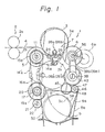
- Figure 1 is a side elevation view of the automatic nearly depleted lap bobbin breaking and removing apparatus in accordance with the present invention, incorporated into a ribbon lap machine.
- reference number 1 denotes a lap feeder composed of a pair of feeding roller, i.e., lap rollers 5.6.
- a lap sheet 4 is unwound from a lap 3 mounted on the pair of the lap rollers 5.6 and is fed to a lap sheet processing mechanism 2, i.e., in this case to a pair of nip rollers 2a and 2b, to apply a drafting action thereto.
- the lap sheet 4 is unwound from the lap 3 and fed to the lap sheet processing mechanism by the synchronous rotation of the lap roller 5 and 6 until a lap bobbin becomes a nearly depleted lap bobbin.
- a nearly depleted lap bobbin breaking and removing apparatus hereafter referred to as a bobbin removing apparatus in accordance with the present invention is actuated.
- the bobbin removing apparatus in accordance with the present invention has a lap holding device 7 pivotally supported on a support shaft 11 supporting one of the lap rollers of the lap feeder on the side of the lap sheet processing mechanism 2, namely, the front lap roller 5.
- the lap holding device 7 has a pair of holding rollers 26a and 26b for holding the nearly depleted lap 3 at the opposite ends of the bobbin thereof. Accordingly, the nearly depleted lap bobbin 3 held by the lap holding device 7 can be revolved down about a support shaft 11 of the front lap roller 5. At that time, the lap sheet 4 is broken between the front lap roller 5 and the nip roller 2a and 2b of the lap sheet processing mechanism 2.
- a width of a gap between the front lap roller 5 and the back lap roller 6 of the lap feeder must be increased to a width allowing the nearly depleted lap bobbin 3 to pass the gap, before moving the nearly depleted lap bobbin 3 downward.
- a plurality of hack lap roller support shaft support arms (hereinafter, referred to as "back support arms”) 39a, 39b and 39c are arranged under the back lap roller 6 to support the support shaft 36 supporting the back lap roller 6.
- the back support arms 39a, 39b and 39c moves the back lap roller 6 around a back lap roller swinging shaft (hereinafter, referred to as "back swinging shaft”) 38 extended in parallel to the support shaft 36 to a position 6a indicated by a broken line in Fig. 1.
- the nearly depleted lap bobbin 3 is moved from a position 3a to a position 3b as indicated by alternate long and two short dashes lines in Fig. 1.
- the nearly depleted lap bobbin 3 drops by gravity from the position 3b onto a conveying device 9 disposed under the position 3b. Then, the conveyor, not shown, of the conveying device 9 conveys the nearly depleted lap bobbin 3 to one end of the textile machine.
- a lap receiver 8 having the shape of a plate is provided to receive the nearly depleted lap bobbin 3 released at the position 3b.
- the lap receiver 8 can swing from a position indicated at 8 to positions 8a and 8b indicated by alternate long and two short dashes lines in Fig. 1 synchronously with the turning motion of the support shaft to place the nearly depleted lap on the conveying device 9 without damaging the bobbin.
- the automatic bobbin removing apparatus in accordance with the present invention will be described hereinafter with reference to Fig. 2 showing a driving mechanism for driving the mechanisms of the automatic bobbin removing apparatus shown in Fig. 1, and Fig. 3 showing the details of an essential portion of the lap holding device 7.
- numerals 10a, 10b and 10c denote frames of the ribbon lap machine and Fig. 2 shows an example in which each lap roller 5.6 supports two lap bobbins. Accordingly, two lap holding devices 7 and 7', and two lap receivers 8 and 8' are shown in Fig. 2.
- the support shaft 11 supporting the front lap roller 5 is supported for rotation in bearings 12a, 12b and 12c on the frames 10a, 10b and 10c.
- a driving gear 13 is fixed to one end of the support shaft 11 to rotate the front lap roller 5 in a given mode of rotation.
- a pair of lap holding device support arms 14a and 14b are supported each at one end thereof for swing motion together with sprockets 15a and 15b fixed to the support shaft 11 in bearings 18a and 18b on the support shaft 11 respectively on the opposite sides of the front lap roller 5.
- a bobbin holding device swinging shaft 17 is extended in parallel to the support shaft 11 supporting the front lap roller 5 and is supported rotatably on the frame 10a, 10b and 10c. As shown in Fig.
- sprockets 19a and 19b are fixed to the lap holding device swinging shaft 17, and chains 16a and 16b are extended between the sprockets 15a and 19a and between the sprockets 15b and 19b fixed on the support shaft 11, respectively.
- a gear 22 mounted on the output shaft 21 of a motor 23 engage a gear 20 fixed to one end of the lap holding device swinging shaft 17.
- the motor 23 is actuated to drive the lap holding device support arms 14a and 14b for swing motion on the support shaft 11 through the lap holding device swinging shaft 17 and the chains 16a and 16b, whereby the lap holding device 14a is moved to and from a position 14'a indicated by an alternate long and two short dashes line in Fig. 1.
- the two lap holding devices 7 and 7' are disposed between the pair of two lap holding device supporting arms 14a and 14b.
- the two lap holding devices 7 and 7' are disposed between the two lap holding device support arms 14a and 14b.
- the two lap holding devices 7 and 7' are substantially the same, only the lap holding device 7 on the left-hand side in Fig. 2 will be described.
- the lap holding device 7 has two lap support bars 24 and 25 extended in parallel to the front lap roller 5. The opposite ends of each of the lap support bars 24 and 25 are fixed to the lap holding device support arms 14a and 14b.
- the lap holding device 7 has a pair of holding rollers 26a and 26b for holding the bobbin of the lap bobbin 3 at the opposite ends thereof, respectively.
- the holding rollers 26a and 26b are supported rotatably through pins 27a and 27b on a bifurcate support arms 28a and 28b, respectively.
- Upper support bars 29a and 29b joined integrally to the lower end of the support arms 28a and 28b are supported pivotally on pins 30a and 30b fixed to the side wall, now shown, of the lap holding device 7.
- a pneumatic cylinder 35a is fixed to a lower member of the lap holding device 7.
- a lower support bar 31a is fixed to the extremity of a piston 34a moved slidably by supplying air into the pneumatic cylinder 35a.
- Lower support bars 31a are supported pivotally at the upper end thereof on pins 30a and 30b and fixed to upper support bars 29a and 29b, respectively.
- the upper support bars 29a and 29b are turned on the pins 30a and 30b to enable the holding rollers 26a and 26b to move between an open position shown in Fig. 3 at which the holding rollers 26a and 26b are spaced apart at a relatively large distance and a closed position shown in Fig. 3 at which the holding rollers 26a and 26b are spaced apart at a relatively small distance to hold and turn downward the lap bobbin supported on the lap support bars 24 and 25 at the opposite ends of its bobbin.
- the back swinging shaft 38 is extended in parallel to the back lap roller 6 and is journaled on the frames 10a, 10b and 10c.
- back support arms 39a, 39b and 39c are fixed to the back swinging shaft 38.
- the support shaft 36 supporting the back lap roller 6 is supported in bearings 40a, 40b and 40c provided respectively on the extremities of the back support arms 39a, 39b and 39c.
- a gear 42 is supported on a bearing 41 attached to one end of the back swinging shaft 38, and a gear 43 engaging the gear 42 is fixed to one end of the support shaft 36.
- the back swinging shaft 38 is turned to move the back lap roller 6 around the back swinging shaft 38 by the back support arms 39a, 39b and 39c between a position 6 indicated by a continuous line and a position 6a shown in Fig. 1.
- the gear 42 is driven for rotation by a driving device, now shown, to rotate the back lap roller 6 through the gear 49.
- the rotation of the gear 42 is transmitted through a rotative interlocking mechanism, not shown, to the gear 13 fixed to the front lap roller 5 to rotate the front lap roller and the back lap roller synchronously.
- a swing motion of the back lap roller 6 is applied by a driving rod 40 having one end fixedly joined to the back swinging shaft 38 and the other end connected to a pneumatic cylinder, not shown.
- the two lap receivers 8 and 8' having the shape of a plate are fixed to brackets 48 and 48' fixed to a lap receiver support shaft 46 extended in parallel to the back lap roller 6.
- the lap receiver support shaft 46 is journaled on the frames 10a, 10b and 10c.
- a gear 47 fixed to the lap receiver support shaft 46 engages an intermediate gear 45 engaging the gear 43 fixed to the back swinging shaft 38.
- the shaft 44 of the intermediate gear 45 is supported on the frame 10b.
- the gear ratio of the gear train consisting of the gears 43, 45 and 47 is determined so as to increase the angle of rotation of the back swinging shaft 38 in transmitting the rotation of the back swinging shaft 38 to the lap receiver support shaft 46 because, as is obvious from Fig. 1, the swing motion of the back lap roller 6 through a very small angle causes the lap receiver 8 to swing through a large angle on the order of 90 degrees.
- a guide 50 is provided on the front side as shown in Fig. 1 to guide the lap.
- the apparatus shown in Fig. 2 is provided with the three frames 10a, 10b and 10c and the three back support arms 39a, 39b and 39c, the frame 10c and the back support arm 39c are provided only for reinforcement, and hence the frame 10c and the back support arm 39c need not necessarily be provided.
- the automatic bobbin removing apparatus of the present invention employs three kinds of driving devices, namely, the motor 23 for swinging the lap holding device 7, the pneumatic cylinder 35a and 35b for operating the pair of holding rollers 26a and 26b of the lap holding device 7, and the pneumatic cylinder actuator, now shown, for rotating the back swinging shaft 38.
- These three kinds of driving devices are controlled for a series of sequential operations by a sequencer. Therefore, when desired, sensors for detecting the positions of the component members may be provided.
- the textile machine for example, the ribbon lap machine
- the lap holding device 7 is turned upward around the support shaft 11 along a circular path through the gap between the lap rollers 5 and 6.
- the back lap roller 6 starts moving to the position 6a (Fig. 1) immediately before the lap support bars 24 and 25 of the lap holding device 7 come into contact with the nearly depleted lap bobbin 3 supported on the lap rollers 5 and 6. Consequently, the nearly depleted lap bobbin 3 is lowered slightly to the position 3a, where the nearly depleted lap bobbin 3 is supported on the lap support bars 24 and 25.
- the holding rollers 26a and 26b of the lap holding device 7 approach the opposite ends of the bobbin of the nearly depleted lap 3 to hold the nearly depleted lap bobbin 3 at the opposite ends of the bobbin at the position 3a.
- the lap holding device 7 is turned downward around the support shaft 11, whereby the lap sheet 4 extending from the nearly depleted lap bobbin 3 at the position 3a to the lap sheet processing mechanism 2 is broken. In most cases, the lap sheet 4 is broken at a position between the front lap roller 5 and the back rollers 2a and 2b of the lap sheet processing mechanism 2.
- the lap holding device 7 releases the hold of the nearly depleted lap bobbin 3 at the position 3a (Fig.
- the automatic lap removing method and the automatic bobbin removing apparatus thus constructed in accordance with the present invention have the following effects.
Landscapes
- Engineering & Computer Science (AREA)
- Textile Engineering (AREA)
- Preliminary Treatment Of Fibers (AREA)
- Spinning Or Twisting Of Yarns (AREA)
Abstract
Description
- The present invention relates to a method of automatically breaking and removing a nearly depleted lap bobbin when a lap bobbin in use becomes a nearly depleted lap bobbin in a textile machine for processing laps which are supplied successively thereto, and an apparatus for carrying out such a method. The textile machine in this application denotes mainly a ribbon lap machine and a comber.
- Where a ribbon lap machine is used as the textile machine, when the lap supplied to the ribbon lap machine is completely depleted, a sensor is activated and the machine is stopped. In a conventional case, the operator interrupts the present work upon the recognition of the lit pilot lamp and goes to the relevant ribbon lap machine or goes to the relevant textile machine after completing the present work, and then the operator breaks and removes an end portion of the residual lap extending over the plate, by hand, removes an empty bobbin, supplies a full lap bobbin to the lap feeder of the textile machine, and superposes the leading end of the lap sheet of the full lap on the trailing end of the preceding lap sheet.
- Since such a textile machine has six or eight delivery units, the textile machine remains inoperative for a long time while the lap changing operation is performed six or eight times and, in some cases, the textile machine remains inoperative for still a longer time in case the lap changing operation, which requires skilled work must be performed over again. Accordingly, an efficiency of operation of the conventional textile machine of the foregoing type is very low.
- Apparatus intended for automatically carrying out those steps of the lap changing operation have been proposed, to solved the above-mentioned problems. However, all those previously proposed apparatus are large in size, are obstructive to cleaning and maintenance work, and are unsatisfactory in safety. Thus, a practically satisfactory apparatus for automatic lap changing operation has not been proposed.
- An object of the present invention is to provide a novel method of automatically breaking and removing a nearly depleted lap bobbin, heretofore impossible, and an apparatus for automatically breaking and removing the nearly depleted lap bobbin and used for carrying out such a method.
- The object of the invention can be attained by a method for automatically breaking and removing a nearly depleted lap bobbin, characterized in that the method comprises steps of: holding the nearly depleted lap bobbin supported on a pair of lap rollers of a lap feeder of the textile machine at the opposite ends of the nearly depleted lap bobbin after the textile machine has been stopped; moving down the nearly depleted lap bobbin through the gap between the pair of lap rollers while the gap between the pair of lap rollers is being increased or after the gap between the pair of lap rollers has been increased to a size allowing the nearly depleted lap bobbin to pass through the gap; breaking a lap sheet of the nearly depleted lap bobbin at an upstream position from the lap processing mechanism arranged on a downstream position from the lap feeder in the textile machine by stretching the lap sheet continuing to the nearly depleted lap bobbin by the movement of the nearly depleted lap bobbin; and releasing the hold of the nearly depleted lap bobbin to drop the nearly depleted lap bobbin onto a conveying device to carry out the nearly depleted lap bobbin.
- An automatic nearly depleted lap bobbin breaking and removing apparatus suitable for carrying out the method for automatically breaking and removing a nearly depleted lap bobbin is characterized in that the apparatus is comprised of a lap holding device capable of holding the nearly depleted lap bobbin supported on front and back lap rollers of a lap feeder at the opposite ends of the bobbin thereof and capable of turning around the front lap roller; a support shaft supporting the back lap roller and capable of moving the back lap roller away from the front lap roller; and a conveying device for receiving the nearly depleted lap bobbin dropped thereon and conveying the nearly depleted lap bobbin in an axial direction of the lap feeder.
- Preferably, the lap holding device comprises: a pair of arms pivotally supported on the shaft of the front lap roller of the lap feeder and extending toward the back lap roller; a pair of lap holding members for holding the nearly depleted lap bobbin, supported on the pair of arms respectively at positions near the extremities of the arms, and spaced apart in parallel from each other with respect to the axial direction of the lap rollers of the lap feeder; and a gripping mechanism capable of moving along a curved path so as to project between the pair of lap holding members and capable of holding the bobbin of the nearly depleted lap bobbin at the opposite ends thereof.
- More preferably, the apparatus is provided with a lap receiver kinematically interlocked with the support shaft so as to be caused to swing by the support shaft between a substantially horizontal position under the lap feeder and a substantially vertical position. It is still more preferable that the lap receiver is comprised of a plate having one end connected to a shaft interlocked with the support shaft by a gear train which increases the angle of rotation of the support shaft.
-
- Figure 1 is a side elevation of an automatic nearly depleted lap bobbin breaking and removing apparatus in a preferred embodiment according to the present invention;
- Figure 2 is a front elevation of a driving mechanism included in the apparatus shown in Fig. 1; and
- Figure 3 is a front elevation of a lap holding device included in the apparatus shown in Fig. 1.
- The present invention will be described in detail with reference to the accompanied drawings illustrating a preferable example of an apparatus for carrying out a method of automatically breaking and removing a nearly depleted lap bobbin in accordance with the present invention.
- Figure 1 is a side elevation view of the automatic nearly depleted lap bobbin breaking and removing apparatus in accordance with the present invention, incorporated into a ribbon lap machine.
- In Fig. 1, reference number 1 denotes a lap feeder composed of a pair of feeding roller, i.e., lap rollers 5.6. A
lap sheet 4 is unwound from alap 3 mounted on the pair of the lap rollers 5.6 and is fed to a lapsheet processing mechanism 2, i.e., in this case to a pair ofnip rollers - The
lap sheet 4 is unwound from thelap 3 and fed to the lap sheet processing mechanism by the synchronous rotation of thelap roller - The bobbin removing apparatus in accordance with the present invention has a
lap holding device 7 pivotally supported on asupport shaft 11 supporting one of the lap rollers of the lap feeder on the side of the lapsheet processing mechanism 2, namely, thefront lap roller 5. Thelap holding device 7 has a pair ofholding rollers depleted lap 3 at the opposite ends of the bobbin thereof. Accordingly, the nearlydepleted lap bobbin 3 held by thelap holding device 7 can be revolved down about asupport shaft 11 of thefront lap roller 5. At that time, thelap sheet 4 is broken between thefront lap roller 5 and thenip roller sheet processing mechanism 2. - A width of a gap between the
front lap roller 5 and theback lap roller 6 of the lap feeder must be increased to a width allowing the nearlydepleted lap bobbin 3 to pass the gap, before moving the nearlydepleted lap bobbin 3 downward. In the embodiment shown in Fig. 1, a plurality of hack lap roller support shaft support arms (hereinafter, referred to as "back support arms") 39a, 39b and 39c are arranged under theback lap roller 6 to support thesupport shaft 36 supporting theback lap roller 6. Theback support arms back lap roller 6 around a back lap roller swinging shaft (hereinafter, referred to as "back swinging shaft") 38 extended in parallel to thesupport shaft 36 to aposition 6a indicated by a broken line in Fig. 1. - Thus the nearly
depleted lap bobbin 3 is moved from aposition 3a to aposition 3b as indicated by alternate long and two short dashes lines in Fig. 1. As shown in Fig. 1, when theholding rollers depleted lap bobbin 3 at aposition 3b at the opposite ends of the bobbin release their hold of the bobbin, the nearlydepleted lap bobbin 3 drops by gravity from theposition 3b onto a conveying device 9 disposed under theposition 3b. Then, the conveyor, not shown, of the conveying device 9 conveys the nearlydepleted lap bobbin 3 to one end of the textile machine. - When the height of the holding rollers from the conveying device is large and the nearly
depleted lap bobbin 3 drops directly onto the conveying device 9 after being released at theposition 3b from theholding rollers lap receiver 8 having the shape of a plate is provided to receive the nearlydepleted lap bobbin 3 released at theposition 3b. Thelap receiver 8 can swing from a position indicated at 8 topositions 8a and 8b indicated by alternate long and two short dashes lines in Fig. 1 synchronously with the turning motion of the support shaft to place the nearly depleted lap on the conveying device 9 without damaging the bobbin. - The automatic bobbin removing apparatus in accordance with the present invention will be described hereinafter with reference to Fig. 2 showing a driving mechanism for driving the mechanisms of the automatic bobbin removing apparatus shown in Fig. 1, and Fig. 3 showing the details of an essential portion of the
lap holding device 7. - In Figure 2,
numerals lap holding devices 7 and 7', and twolap receivers 8 and 8' are shown in Fig. 2. - In Fig. 2, the
support shaft 11 supporting thefront lap roller 5 is supported for rotation inbearings frames driving gear 13 is fixed to one end of thesupport shaft 11 to rotate thefront lap roller 5 in a given mode of rotation. A pair of lap holding device supportarms sprockets support shaft 11 in bearings 18a and 18b on thesupport shaft 11 respectively on the opposite sides of thefront lap roller 5. A bobbin holdingdevice swinging shaft 17 is extended in parallel to thesupport shaft 11 supporting thefront lap roller 5 and is supported rotatably on theframe sprockets device swinging shaft 17, andchains 16a and 16b are extended between thesprockets sprockets support shaft 11, respectively. Agear 22 mounted on theoutput shaft 21 of amotor 23 engage agear 20 fixed to one end of the lap holdingdevice swinging shaft 17. Themotor 23 is actuated to drive the lap holding device supportarms support shaft 11 through the lap holdingdevice swinging shaft 17 and thechains 16a and 16b, whereby thelap holding device 14a is moved to and from a position 14'a indicated by an alternate long and two short dashes line in Fig. 1. - In the bobbin holding device shown in Fig. 2, the two
lap holding devices 7 and 7' are disposed between the pair of two lap holdingdevice supporting arms - As shown in Fig. 2, the two
lap holding devices 7 and 7' are disposed between the two lap holding device supportarms lap holding devices 7 and 7' are substantially the same, only thelap holding device 7 on the left-hand side in Fig. 2 will be described. Thelap holding device 7 has twolap support bars front lap roller 5. The opposite ends of each of thelap support bars arms lap holding device 7 has a pair ofholding rollers lap bobbin 3 at the opposite ends thereof, respectively. Theholding rollers pins bifurcate support arms 28a and 28b, respectively.Upper support bars 29a and 29b joined integrally to the lower end of thesupport arms 28a and 28b are supported pivotally onpins 30a and 30b fixed to the side wall, now shown, of thelap holding device 7. Apneumatic cylinder 35a is fixed to a lower member of thelap holding device 7. A lower support bar 31a is fixed to the extremity of a piston 34a moved slidably by supplying air into thepneumatic cylinder 35a. Lower support bars 31a are supported pivotally at the upper end thereof onpins 30a and 30b and fixed toupper support bars 29a and 29b, respectively. When thepneumatic cylinder actuators pneumatic cylinder actuator 35b is disposed on the backside of Fig. 3 and hence is not shown) are actuated, theupper support bars 29a and 29b are turned on thepins 30a and 30b to enable theholding rollers holding rollers holding rollers lap support bars - A mechanism for swinging the
back lap roller 6 and thelap receiver 8 will be described hereinafter. Theback swinging shaft 38 is extended in parallel to theback lap roller 6 and is journaled on theframes back support arms back swinging shaft 38. Thesupport shaft 36 supporting theback lap roller 6 is supported inbearings 40a, 40b and 40c provided respectively on the extremities of theback support arms gear 42 is supported on abearing 41 attached to one end of theback swinging shaft 38, and agear 43 engaging thegear 42 is fixed to one end of thesupport shaft 36. Thus, theback swinging shaft 38 is turned to move theback lap roller 6 around theback swinging shaft 38 by theback support arms position 6 indicated by a continuous line and aposition 6a shown in Fig. 1. While the ribbon lap machine is in the normal operation, thegear 42 is driven for rotation by a driving device, now shown, to rotate theback lap roller 6 through thegear 49. The rotation of thegear 42 is transmitted through a rotative interlocking mechanism, not shown, to thegear 13 fixed to thefront lap roller 5 to rotate the front lap roller and the back lap roller synchronously. - A swing motion of the
back lap roller 6 is applied by a drivingrod 40 having one end fixedly joined to theback swinging shaft 38 and the other end connected to a pneumatic cylinder, not shown. - As shown in Fig. 2, the two
lap receivers 8 and 8' having the shape of a plate are fixed tobrackets 48 and 48' fixed to a lapreceiver support shaft 46 extended in parallel to theback lap roller 6. The lapreceiver support shaft 46 is journaled on theframes gear 47 fixed to the lapreceiver support shaft 46 engages anintermediate gear 45 engaging thegear 43 fixed to theback swinging shaft 38. Theshaft 44 of theintermediate gear 45 is supported on theframe 10b. Preferably, the gear ratio of the gear train consisting of thegears back swinging shaft 38 in transmitting the rotation of theback swinging shaft 38 to the lapreceiver support shaft 46 because, as is obvious from Fig. 1, the swing motion of theback lap roller 6 through a very small angle causes thelap receiver 8 to swing through a large angle on the order of 90 degrees. Preferably, aguide 50 is provided on the front side as shown in Fig. 1 to guide the lap. - Although the apparatus shown in Fig. 2 is provided with the three
frames back support arms frame 10c and theback support arm 39c are provided only for reinforcement, and hence theframe 10c and theback support arm 39c need not necessarily be provided. - As stated above, the automatic bobbin removing apparatus of the present invention employs three kinds of driving devices, namely, the
motor 23 for swinging thelap holding device 7, thepneumatic cylinder rollers lap holding device 7, and the pneumatic cylinder actuator, now shown, for rotating theback swinging shaft 38. These three kinds of driving devices are controlled for a series of sequential operations by a sequencer. Therefore, when desired, sensors for detecting the positions of the component members may be provided. - The operation of the automatic bobbin removing apparatus of the present invention will be described hereinafter.
- Upon the depletion of the lap supported on the
lap rollers lap holding device 7 is turned upward around thesupport shaft 11 along a circular path through the gap between thelap rollers back lap roller 6 starts moving to theposition 6a (Fig. 1) immediately before the lap support bars 24 and 25 of thelap holding device 7 come into contact with the nearlydepleted lap bobbin 3 supported on thelap rollers depleted lap bobbin 3 is lowered slightly to theposition 3a, where the nearlydepleted lap bobbin 3 is supported on the lap support bars 24 and 25. Then, the holdingrollers lap holding device 7 approach the opposite ends of the bobbin of the nearlydepleted lap 3 to hold the nearlydepleted lap bobbin 3 at the opposite ends of the bobbin at theposition 3a. Then, thelap holding device 7 is turned downward around thesupport shaft 11, whereby thelap sheet 4 extending from the nearlydepleted lap bobbin 3 at theposition 3a to the lapsheet processing mechanism 2 is broken. In most cases, thelap sheet 4 is broken at a position between thefront lap roller 5 and theback rollers sheet processing mechanism 2. Thelap holding device 7 releases the hold of the nearlydepleted lap bobbin 3 at theposition 3a (Fig. 1) to drop the nearlydepleted lap bobbin 3 onto thelap receiver 8. Then, thelap receiver 8 moves through a position 8a to aposition 8b while the nearlydepleted lap bobbin 3 is guided by theguide 50 throughpositions depleted lap bobbin 3 from the textile machine. Theback lap roller 6 is returned to the original position in synchronism with the circular swing motion of thelap receiver 8. Finally, a full lap, which has been held behind theback lap roller 6, is supplied onto thelap rollers - The automatic lap removing method and the automatic bobbin removing apparatus thus constructed in accordance with the present invention have the following effects.
- (1) Since the defective portion of a lap fleece (the leading end of the lap sheet in the preceding process) can be removed, the quality of the fleece produced by the textile machine can be improved and unsuccessful lap sheet piecing operation is obviated.
- (2) Since the automatic bobbin removing apparatus is disposed substantially under the essential portion of the textile machine, work for the maintenance and cleaning of the textile machine can easily and safely be performed, and, since the automatic bobbin removing apparatus is contained within the main frame of the textile machine, the automatic bobbin removing apparatus does not spoil the appearance of the textile machine.
- (3) Since the lap holding device holding the lap pulls the lap sheet, the lap sheet can surely be broken.
- (4) Since the automatic bobbin removing apparatus is compact and is designed for installation under the essential portion of the textile machine, an automatic lap piecing apparatus can easily be incorporated into the textile machine.
-
- 1
- Lap feeder
- 2
- Lap sheet processing mechanism
- 3
- Nearly depleted lap
- 4
- Lap sheet
- 5
- Front lap roller
- 6
- Back lap roller
- 7
- Lap holding device
- 8
- Lap receiver
- 9
- Conveying device
Claims (5)
- A method of automatically breaking and removing a nearly depleted lap bobbin when a lap bobbin in use becomes nearly depleted in a textile machine for processing laps which are supplied successively thereto, characterized in that said method comprises steps of: holding the nearly depleted lap bobbin supported on a pair of lap rollers of a lap feeder of the textile machine at the opposite ends of the nearly depleted lap bobbin after the textile machine has been stopped; moving down the nearly depleted lap bobbin through the gap between the pair of lap rollers while the gap between the pair of lap rollers is being increased or after the gap between the pair of lap rollers has been increased to a size allowing the nearly depleted lap bobbin to pass through the gap; breaking a lap sheet of the nearly depleted lap bobbin at an position upstream of the lap processing mechanism arranged at a position downstream of the lap feeder in the textile machine by stretching the lap sheet continuing to the nearly depleted lap bobbin by the movement of the nearly depleted lap bobbin; and releasing the hold of the nearly depleted lap bobbin to drop the nearly depleted lap bobbin onto a conveying device to carry out the nearly depleted lap bobbin.
- An automatic nearly depleted lap bobbin breaking and removing apparatus used in a lap treating textile machine composed of a lap feeder having a pair of lap rollers for supporting a lap bobbin thereon and feeding a lap sheet unwound from the lap bobbin, and a lap processing mechanism disposed at a position downstream of the lap feeder: characterized in that said apparatus is comprised of a lap holding device supported for turning motion around the front lap roller of the lap feeder on the side of the lap processing mechanism and capable of holding a nearly depleted lap bobbin at the opposite ends of the bobbin thereof; a support shaft supporting the back lap roller of the lap feeder and capable of moving the back lap roller away from the front lap roller; and a conveying device for receiving the nearly depleted lap bobbin dropped thereon and conveying the nearly depleted lap bobbin in an axial direction of the lap feeder.
- An apparatus according to claim 2, wherein said lap holding device comprises: a pair of arms pivotally supported on the shaft of the front lap roller of the lap feeder and extending toward the back lap roller; a pair of lap holding members for holding the nearly depleted lap bobbin supported on the pair of arms respectively at positions near the extremities of the arms, and spaced a part from and in parallel with each other with respect to the axial direction of the lap rollers of the lap feeder; and a gripping mechanism capable of moving along a curved path so as to project between the pair of lap holding members and capable of holding the bobbin of the nearly depleted lap bobbin at the opposite ends thereof.
- An apparatus according to claim 2, wherein a lap receiver kinematically interlocked with the support shaft so as to be caused to swing by the support shaft between a substantially horizontal position under the lap feeder and a substantially vertical position is provided.
- An apparatus according to claim 2, wherein said lap receiver is comprised of a plate having one end connected to a shaft interlocked with the support shaft by a gear train which increases the angle of rotation of the support shaft.
Applications Claiming Priority (2)
| Application Number | Priority Date | Filing Date | Title |
|---|---|---|---|
| JP17697288A JP2645423B2 (en) | 1988-07-18 | 1988-07-18 | Method and apparatus for automatically cutting and removing small ball wrap bobbins |
| PCT/JP1989/001017 WO1991005097A1 (en) | 1988-07-18 | 1989-10-04 | Method and apparatus for automatically cutting and removing small diameter lap bobbin |
Publications (3)
| Publication Number | Publication Date |
|---|---|
| EP0452491A1 true EP0452491A1 (en) | 1991-10-23 |
| EP0452491A4 EP0452491A4 (en) | 1992-04-01 |
| EP0452491B1 EP0452491B1 (en) | 1995-11-29 |
Family
ID=16022931
Family Applications (1)
| Application Number | Title | Priority Date | Filing Date |
|---|---|---|---|
| EP19890911092 Expired - Lifetime EP0452491B1 (en) | 1988-07-18 | 1989-10-04 | Method and apparatus for automatically cutting and removing small diameter lap bobbin |
Country Status (5)
| Country | Link |
|---|---|
| US (1) | US5156241A (en) |
| EP (1) | EP0452491B1 (en) |
| JP (1) | JP2645423B2 (en) |
| DE (1) | DE68924985T2 (en) |
| WO (1) | WO1991005097A1 (en) |
Cited By (1)
| Publication number | Priority date | Publication date | Assignee | Title |
|---|---|---|---|---|
| EP0593391A1 (en) * | 1992-10-16 | 1994-04-20 | Maschinenfabrik Rieter Ag | Apparatus for wound package changing |
Families Citing this family (5)
| Publication number | Priority date | Publication date | Assignee | Title |
|---|---|---|---|---|
| JPH04256392A (en) * | 1991-02-08 | 1992-09-11 | Sumitomo Electric Ind Ltd | Frequency multiplex optical transmission device |
| US5427294A (en) * | 1993-11-12 | 1995-06-27 | Reynolds Consumer Products Inc. | Method and apparatus for breaking film perforations |
| US20040014173A1 (en) * | 1999-05-14 | 2004-01-22 | Anderson David W. | Novel polynucleotides, polypeptides encoded thereby and methods of use thereof |
| DK2335910T3 (en) * | 2009-12-18 | 2018-05-28 | Lm Wind Power Int Tech Ii Aps | Loading apparatus and method for loading rolls of fiber-based layer material to an application unit |
| CN115491793A (en) * | 2022-06-23 | 2022-12-20 | 南通支云纺织工艺品有限公司 | Cotton web bundling mechanism of intelligent combing machine |
Citations (2)
| Publication number | Priority date | Publication date | Assignee | Title |
|---|---|---|---|---|
| FR890150A (en) * | 1942-02-14 | 1944-01-28 | Elmag Elsassische Maschb A G | Device for the application of feed rollers on straight combers |
| US2559074A (en) * | 1945-05-17 | 1951-07-03 | Terrell Mach Co | Lap changer for combing machines |
Family Cites Families (7)
| Publication number | Priority date | Publication date | Assignee | Title |
|---|---|---|---|---|
| US3582010A (en) * | 1968-09-18 | 1971-06-01 | Reynolds Metals Co | Apparatus for and method of making a coil construction |
| JPS4829814B1 (en) * | 1970-09-08 | 1973-09-13 | ||
| JPS4839060Y1 (en) * | 1970-12-28 | 1973-11-17 | ||
| JPS5225125A (en) * | 1975-08-18 | 1977-02-24 | Nisshin Spinning | Comber lap conveying apparatus being able to return empty core |
| JPS5795317A (en) * | 1980-11-27 | 1982-06-14 | Tokyu Kk | Lap doffer in comber |
| JP2628075B2 (en) * | 1988-09-06 | 1997-07-09 | 株式会社金田機械製作所 | Auto reel loader |
| CH676249A5 (en) * | 1988-11-03 | 1990-12-28 | Rieter Ag Maschf |
-
1988
- 1988-07-18 JP JP17697288A patent/JP2645423B2/en not_active Expired - Lifetime
-
1989
- 1989-10-04 DE DE1989624985 patent/DE68924985T2/en not_active Expired - Fee Related
- 1989-10-04 US US07/476,498 patent/US5156241A/en not_active Expired - Fee Related
- 1989-10-04 WO PCT/JP1989/001017 patent/WO1991005097A1/en active IP Right Grant
- 1989-10-04 EP EP19890911092 patent/EP0452491B1/en not_active Expired - Lifetime
Patent Citations (2)
| Publication number | Priority date | Publication date | Assignee | Title |
|---|---|---|---|---|
| FR890150A (en) * | 1942-02-14 | 1944-01-28 | Elmag Elsassische Maschb A G | Device for the application of feed rollers on straight combers |
| US2559074A (en) * | 1945-05-17 | 1951-07-03 | Terrell Mach Co | Lap changer for combing machines |
Non-Patent Citations (1)
| Title |
|---|
| See also references of WO9105097A1 * |
Cited By (2)
| Publication number | Priority date | Publication date | Assignee | Title |
|---|---|---|---|---|
| EP0593391A1 (en) * | 1992-10-16 | 1994-04-20 | Maschinenfabrik Rieter Ag | Apparatus for wound package changing |
| US6059221A (en) * | 1992-10-16 | 2000-05-09 | Rieter Machine Works, Ltd. | Apparatus for changing a lap |
Also Published As
| Publication number | Publication date |
|---|---|
| US5156241A (en) | 1992-10-20 |
| DE68924985D1 (en) | 1996-01-11 |
| EP0452491B1 (en) | 1995-11-29 |
| JP2645423B2 (en) | 1997-08-25 |
| JPH0226925A (en) | 1990-01-29 |
| WO1991005097A1 (en) | 1991-04-18 |
| EP0452491A4 (en) | 1992-04-01 |
| DE68924985T2 (en) | 1996-04-18 |
Similar Documents
| Publication | Publication Date | Title |
|---|---|---|
| CN100402719C (en) | Method and apparatus of reconnecting for air-flow spinner | |
| EP0223215B1 (en) | Apparatus for selecting and feeding web material | |
| JPH07189054A (en) | Can distribution device | |
| US4535944A (en) | Spinning machine with a doffing apparatus | |
| EP0452491B1 (en) | Method and apparatus for automatically cutting and removing small diameter lap bobbin | |
| US4539804A (en) | Method and apparatus for starting the operation of a friction spinning machine | |
| US3863751A (en) | Feeding devices for textile machines | |
| EP0220945B1 (en) | Continuous spinning system for connecting a plurality of carding machines with a drawing frame | |
| US5544389A (en) | Sliver piecing in spinning machines | |
| JPH0663144B2 (en) | Sliver supply method in spinning machine | |
| US5280699A (en) | Method and apparatus for disposing an end of a roving bobbin for intake into the drafting device of a textile spinning machine | |
| US5430917A (en) | Method and apparatus for piecing lap sheets | |
| JPH06207333A (en) | Apparatus for cutting sliver in filling station of sliver manufacturing fiber machine | |
| CZ245793A3 (en) | Process and apparatus for automatic feeding of a fiber strand | |
| EP0481922A1 (en) | Method and apparatus for piecing slivers | |
| US5237725A (en) | Method and apparatus for opening fiber bales | |
| JP3070322B2 (en) | Sliver cutting method and sliver cutting device | |
| CN109969861A (en) | Yarn winding machine and Cylinder feeder method | |
| JPH0663143B2 (en) | Sliver gripping and feeding device in spinning machine | |
| JPH05117921A (en) | Automatic lap connection | |
| US5144731A (en) | Automatic lap piecing method and an apparatus for carrying out the same | |
| JPH10280235A (en) | Method and apparatus for cutting sliver in spinning machine | |
| JP2966192B2 (en) | Method and apparatus for winding woven fabric around cross roll | |
| EP0683254B1 (en) | Device for automatically doffing the hollow lap rollers from a framing of a condenser card | |
| JP2768535B2 (en) | Spinner sliver splicing device |
Legal Events
| Date | Code | Title | Description |
|---|---|---|---|
| PUAI | Public reference made under article 153(3) epc to a published international application that has entered the european phase |
Free format text: ORIGINAL CODE: 0009012 |
|
| 17P | Request for examination filed |
Effective date: 19900629 |
|
| AK | Designated contracting states |
Kind code of ref document: A1 Designated state(s): CH DE IT LI |
|
| A4 | Supplementary search report drawn up and despatched |
Effective date: 19920211 |
|
| AK | Designated contracting states |
Kind code of ref document: A4 Designated state(s): CH DE IT LI |
|
| 17Q | First examination report despatched |
Effective date: 19930813 |
|
| ITF | It: translation for a ep patent filed |
Owner name: INTERPATENT ST.TECN. BREV. |
|
| GRAA | (expected) grant |
Free format text: ORIGINAL CODE: 0009210 |
|
| AK | Designated contracting states |
Kind code of ref document: B1 Designated state(s): CH DE IT LI |
|
| REF | Corresponds to: |
Ref document number: 68924985 Country of ref document: DE Date of ref document: 19960111 |
|
| REG | Reference to a national code |
Ref country code: CH Ref legal event code: NV Representative=s name: BUGNION S.A. |
|
| PLBE | No opposition filed within time limit |
Free format text: ORIGINAL CODE: 0009261 |
|
| STAA | Information on the status of an ep patent application or granted ep patent |
Free format text: STATUS: NO OPPOSITION FILED WITHIN TIME LIMIT |
|
| 26N | No opposition filed | ||
| PGFP | Annual fee paid to national office [announced via postgrant information from national office to epo] |
Ref country code: CH Payment date: 20020930 Year of fee payment: 14 |
|
| PGFP | Annual fee paid to national office [announced via postgrant information from national office to epo] |
Ref country code: DE Payment date: 20021210 Year of fee payment: 14 |
|
| PG25 | Lapsed in a contracting state [announced via postgrant information from national office to epo] |
Ref country code: LI Free format text: LAPSE BECAUSE OF NON-PAYMENT OF DUE FEES Effective date: 20031031 Ref country code: CH Free format text: LAPSE BECAUSE OF NON-PAYMENT OF DUE FEES Effective date: 20031031 |
|
| PG25 | Lapsed in a contracting state [announced via postgrant information from national office to epo] |
Ref country code: DE Free format text: LAPSE BECAUSE OF NON-PAYMENT OF DUE FEES Effective date: 20040501 |
|
| REG | Reference to a national code |
Ref country code: CH Ref legal event code: PL |
|
| PG25 | Lapsed in a contracting state [announced via postgrant information from national office to epo] |
Ref country code: IT Free format text: LAPSE BECAUSE OF NON-PAYMENT OF DUE FEES;WARNING: LAPSES OF ITALIAN PATENTS WITH EFFECTIVE DATE BEFORE 2007 MAY HAVE OCCURRED AT ANY TIME BEFORE 2007. THE CORRECT EFFECTIVE DATE MAY BE DIFFERENT FROM THE ONE RECORDED. Effective date: 20051004 |