EP0452434B1 - Vice-grip wrench for chain conveyors - Google Patents
Vice-grip wrench for chain conveyors Download PDFInfo
- Publication number
- EP0452434B1 EP0452434B1 EP90914891A EP90914891A EP0452434B1 EP 0452434 B1 EP0452434 B1 EP 0452434B1 EP 90914891 A EP90914891 A EP 90914891A EP 90914891 A EP90914891 A EP 90914891A EP 0452434 B1 EP0452434 B1 EP 0452434B1
- Authority
- EP
- European Patent Office
- Prior art keywords
- lever
- jaw
- clamping jaw
- housing
- operating lever
- Prior art date
- Legal status (The legal status is an assumption and is not a legal conclusion. Google has not performed a legal analysis and makes no representation as to the accuracy of the status listed.)
- Expired - Lifetime
Links
Images


Classifications
-
- B—PERFORMING OPERATIONS; TRANSPORTING
- B65—CONVEYING; PACKING; STORING; HANDLING THIN OR FILAMENTARY MATERIAL
- B65H—HANDLING THIN OR FILAMENTARY MATERIAL, e.g. SHEETS, WEBS, CABLES
- B65H29/00—Delivering or advancing articles from machines; Advancing articles to or into piles
- B65H29/003—Delivering or advancing articles from machines; Advancing articles to or into piles by grippers
-
- B—PERFORMING OPERATIONS; TRANSPORTING
- B65—CONVEYING; PACKING; STORING; HANDLING THIN OR FILAMENTARY MATERIAL
- B65H—HANDLING THIN OR FILAMENTARY MATERIAL, e.g. SHEETS, WEBS, CABLES
- B65H2402/00—Constructional details of the handling apparatus
- B65H2402/50—Machine elements
- B65H2402/54—Springs, e.g. helical or leaf springs
Definitions
- the present invention relates to a clamp for chain conveyors according to the preamble of claim 1.
- a pair of pliers of this type is known from GB-A-803027.
- the clamping pliers are opened and closed by means of a control cam arranged on the chain conveyor's circulation path. If a cam roller mounted on the operating lever runs onto the cam during operation of the chain conveyor, the pliers closes and remains closed until the cam roller leaves the cam. This has the disadvantage that the control curve must be present along the entire transport path of the chain transporter, which is complex for long transport routes.
- the disadvantage here is that the opening travel required on the actuating lever is comparatively large, which prevents rapid opening of the clamping pliers.
- Another disadvantage is that the closing force exerted by the spring in thin printed products is considerably smaller than in thick printed products, which makes it difficult to convey them in the correct position.
- the present invention therefore has the task of eliminating the disadvantages mentioned in a clamp of the type mentioned at the outset without accepting the disadvantages caused by a simple spring mechanism.
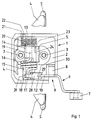
- the clamping pliers shown have a substantially rectangular, box-shaped and upwardly open housing 1 made of a plastic.
- the clamping pliers have a jaw 4 fastened to the housing base 2 with screws 3, a pivotably movable jaw 5 and an actuating lever 6.
- the plate-shaped jaws 4 and 5 are shown interrupted in Fig. 1 for clarity.
- the screws 3 can also serve to fasten the clamp on a chain conveyor, not shown.
- the lever 6 is provided with a roller 7 for its actuation by an external organ.
- the lever 6 is pivotally mounted on a shaft 8 arranged in the housing 1, specifically in a corner cutout 9 of the housing 1 (FIG. 1).
- the lever 6 is formed with two arms and on its lever arm 10 opposite the roller 7 has a shoulder 11 which comes to rest in the closed position of the clamping pliers on the inside of the base 2 (FIG. 3) and thus the pivoting movement of the lever 6 around the Shaft 8 limited in one pivot direction.
- the lever arm 10 is provided with a lug 12 having a bore.
- a bearing pin 13 is also arranged parallel to the shaft 8.
- the bearing pin 13 carries a first, on this rotatable sleeve part 14 and, axially separated from the sleeve part 14, a second, on the bearing pin 13 rotatable sleeve part 15.
- the two independently rotatable sleeve parts 14 and 15 are by a coaxial coil spring 16 (Fig. 1st ) connected to each other, the helical spring 16 being inserted at one end 17 into a lug 18 of the second sleeve part 15 and at its other end 19 (FIG. 1) into the first sleeve part 14.
- a second coaxial coil spring 20 is arranged as a return spring, which is inserted at one end 21 into a side wall 22 of the housing 1 and at its other end 23 into a nose 24 of the first sleeve part 14.
- the movable jaw 5 is firmly anchored to a projection 25 of the first sleeve part 14 (FIGS. 2, 3) by means of screws 26 (FIG. 2). It can thus be pivoted on the bearing pin 13 against the force of the helical spring 20 from the open position according to FIG. 2 to the closed position according to FIG. 3.
- the open position of the jaw 5 is limited in that the jaw 5 comes to rest on an upper housing edge 27 (FIGS. 2, 3).
- the lever 6 is connected to the second sleeve part 15 via a tab 28, the nose 12 of the lever arm 10 being rotatably mounted in a slot 29 of the tab 28 by means of a bolt 30.
- the other end of the tab 28 is mounted in a slot 31 of the nose 18 of the second sleeve part 15 by means of the end 17 of the coil spring 16.
- a rotary movement of the lever 6 thus causes a rotation of the second sleeve part 15 or a rotary movement of the helical spring 16 via the tab 28.
- the return spring 20 acts from the first sleeve part 14 via the first coil spring 16 and the tab 28 also on the lever 6 and holds it in the position shown in FIG. 2. Since the lever 6 is freely movable in this case is, the coil spring 16 is to be regarded as a quasi-rigid connection between the first sleeve part 14 and the lever 6.
- the helical spring 16 is twisted when the lever 6 is pivoted further in the direction of the arrow 32, that is to say tensioned since the first sleeve part 14 can no longer rotate.
- the counterforce now acting on the lever 6 is approximately equal to the force which the movable jaw 5 exerts on the fixed jaw 4, directly or via the object 34.
- the lever 6 is pivoted in a simple manner in the opposite direction to the arrow 32, the coil spring 16 first opening the movable jaw 5 and pressing the lever 6 downward and then the return spring 20 for a full opening, including the pivoting of the lever 6 in its position according to FIG. 2.
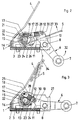
- FIGS. 4 to 6 The further embodiment of the clamping pliers according to the invention shown in FIGS. 4 to 6 makes use of another dead center mechanism, namely a locking curve instead of a knee joint.
- the clamping pliers in turn have an approximately rectangular, box-shaped housing 41 with a housing base 42, to which a clamping jaw 44, shown broken off in FIG. 4, is fastened by means of screws 43.
- a pivotably movable jaw 45 is wire-shaped.
- the clamping pliers again have a lever 46 for their actuation, which is provided with a roller 47.
- the lever 46 is connected to a first shaft 48 which is rotatably mounted in the housing 41 and which is subjected to the force of a coaxial restoring spring 49 which is supported on the housing base 42 and which thus rests the lever 46 in the position shown in FIG. 5 against a housing stop 50 presses.
- a second shaft 51 which is designed as a hollow shaft and, like the housing 41, is made of a plastic, is rotatably mounted.
- the shaft 51 is provided in the interior of the housing 41 with a longitudinal slot 52.
- the shaft 51 projects beyond it and is provided with an integrally formed lever arm 53.
- the lever arm 53 has a straight longitudinal groove 54 which is open at the radially outer end and has a sharp-angled bend 55 in its radially outer end region and a curvature 56 on the other side (FIGS. 5, 6).
- the lever 46 is provided on its side opposite the groove 54 with a roller 57 which is guided in the groove 54. A pivoting movement of the lever 46 thus causes the shaft 51 to rotate.
- the wire-shaped, movable jaw 45 is wound inside the housing 41 with its two side parts 58 and 59 around the shaft 51 and with its ends 60 and 61 in the slot 52 of the Shaft 51 inserted.
- the winding sections of the movable jaw 45 thus each form a helical spring 62 or 63, which connect the jaw 45 to the lever 46 via the shaft 51 and the lever arm 53.
Abstract
Description
Die vorliegende Erfindung betrifft eine Klemmzange für Kettentransporteure gemäss dem Oberbegriff des Patentanspruchs 1.The present invention relates to a clamp for chain conveyors according to the preamble of
Eine Klemmzange dieser Art ist aus der GB-A-803027 bekannt. Das Öffnen und Schliessen der Klemmzange erfolgt mittels einer am Umlaufweg des Kettentransporteurs angeordneten Steuerkurve. Läuft während des Betriebs des Kettentransporteurs eine am Betätigungshebel gelagerte Nockenrolle auf die Steuerkurve auf, schliesst die Zange und bleibt geschlossen, bis die Nockenrolle die Steuerkurve verlässt. Damit ist der Nachteil verbunden, dass die Steurkurve entlang dem ganzen Transportweg des Kettentransporteurs vorhanden sein muss, was bei grossen Transportstrecken aufwendig ist.A pair of pliers of this type is known from GB-A-803027. The clamping pliers are opened and closed by means of a control cam arranged on the chain conveyor's circulation path. If a cam roller mounted on the operating lever runs onto the cam during operation of the chain conveyor, the pliers closes and remains closed until the cam roller leaves the cam. This has the disadvantage that the control curve must be present along the entire transport path of the chain transporter, which is complex for long transport routes.
Dieser Nachteil ist bei Klemmzangen gemäss der FR-A-2327181 bzw. der EP-A-386442 Stand der Technnik gemäß Artikel 54(3) EPÜ behoben. Bei diesen älteren Klemmzangen steht die bewegliche Klemmbacke analog dem Schaltglied eines elektrischen Kipp- oder Tastschalters unter Wirkung einer Springfeder und wird analog einem Schalter an der Beschickungs- und Entnahmestelle je einmal betätigt. Die geometrische Anordnung der Springfeder ist dabei so zu wählen, dass sie in der Schliessstellung - gleichgültig ob sie ein dünnes oder ein dickes Druckprodukt festhält - genügend Abstand zu Totlage hat. Ist dieser zu gering, kann sie aufspringen, wenn Schwingungen oder Schläge im mit hoher Geschwindigkeit umlaufenden Kettenförderer auftreten. Nachteilig ist dabei, dass der am Betätigungshebel erforderliche Öffnungsweg vergleichsweise gross ist, was einem raschen Öffnen der Klemmzange entgegensteht. Ein weiterer Nachteil besteht darin, dass die bei dünnen Druckprodukten von der Springfeder ausgeführte Schliesskraft wesentlich kleiner ist als bei dicken Druckprodukten, was deren lagegenaue Förderung erschwert.This disadvantage is eliminated in the case of clamping pliers according to FR-A-2327181 or EP-A-386442 prior art according to Article 54 (3) EPC. In these older clamps, the movable jaw is analogous to the switching element of an electrical toggle or pushbutton switch under the action of a spring and is actuated once, analogously to a switch at the loading and unloading point. The geometrical arrangement of the spring is to be chosen so that in the closed position - regardless of whether it holds a thin or a thick printed product - it has enough clearance from the dead center. If this is too low, it can jump open if vibrations or impacts occur in the chain conveyor rotating at high speed. The disadvantage here is that the opening travel required on the actuating lever is comparatively large, which prevents rapid opening of the clamping pliers. Another disadvantage is that the closing force exerted by the spring in thin printed products is considerably smaller than in thick printed products, which makes it difficult to convey them in the correct position.
Die vorliegende Erfindung stellt sich daher die Aufgabe, die bei einer Klemmzange der eingangs genannten Art erwähnten Nachteile zu beseitigen, ohne die durch einen einfachen Springfedermechanismus bedingten Nachteile in Kauf zu nehmen.The present invention therefore has the task of eliminating the disadvantages mentioned in a clamp of the type mentioned at the outset without accepting the disadvantages caused by a simple spring mechanism.
Erfindungsgemäss wird diese Aufgabe durch die kennzeichnenden Merkmale des Patentanspruchs 1 gelöst.According to the invention, this object is achieved by the characterizing features of
Ausführungsbeispiele der Erfindung werden nachstehend anhand der Zeichnungen erläutert. Es zeigen:
- Fig. 1
- eine Draufsicht auf eine erste Ausführungsform der erfindungsgemässen Klemmzange mit einem Kniegelenk, wobei die Klemmzange in ihrer Schliessstellung dargestellt ist;
- Fig. 2
- eine Seitenansicht, teilweise im Schnitt, der Klemmzange der Fig. 1, jedoch in ihrer Offenstellung;
- Fig. 3
- eine Seitenansicht, teilweise im Schnitt, der Klemmzange der Fig. 1 in ihrer Schliessstellung gemäss Fig. 1,
- Fig. 4
- eine Draufsicht, teilweise im Schnitt, auf eine zweite Ausführungsform der erfindungsgemässen Klemmzange mit einer Rastkurve, wobei die Klemmzange in ihrer Schliessstellung dargestellt ist;
- Fig. 5
- eine Seitenansicht der Klemmzange der Fig. 4, jedoch in ihrer Offenstellung gemäss Fig. 4 und
- Fig. 6
- eine Seitenansicht der Klemmzange der Fig. 4 in ihrer Schliessstellung gemäss Fig. 1.
- Fig. 1
- a plan view of a first embodiment of the clamp according to the invention with a knee joint, the clamp being shown in its closed position;
- Fig. 2
- a side view, partially in section, of the clamp of Figure 1, but in its open position.
- Fig. 3
- 2 shows a side view, partly in section, of the clamping pliers of FIG. 1 in their closed position according to FIG. 1,
- Fig. 4
- a plan view, partly in section, of a second embodiment of the clamping pliers according to the invention with a locking curve, the clamping pliers being shown in their closed position;
- Fig. 5
- 4, but in its open position according to FIG. 4 and
- Fig. 6
- 4 in its closed position according to FIG. 1.
Gemäss den Fig. 1 bis 3 weist die dargestellte Klemmzange ein im wesentlichen rechteckiges, kastenförmiges und nach oben offenes Gehäuse 1 aus einem Kunststoff auf. Als äussere aktive Elemente weist die Klemmzange eine am Gehäuseboden 2 mit Schrauben 3 befestigte Klemmbacke 4, eine schwenkbar bewegliche Klemmbacke 5 und einen Betätigungshebel 6 auf. Die plattenförmigen Klemmbacken 4 und 5 sind in der Fig. 1 übersichtshalber unterbrochen dargestellt. Die Schrauben 3 können gleichzeitig auch zum Befestigen der Klemmzange auf einem nicht dargestellten Kettentransporteur dienen. Der Hebel 6 ist zu seiner Betätigung durch ein äusseres Organ mit einer Rolle 7 versehen.1 to 3, the clamping pliers shown have a substantially rectangular, box-shaped and upwardly
Der Hebel 6 ist auf einer im Gehäuse 1 angeordneten Welle 8 schwenkbar gelagert, und zwar in einem Eckausschnitt 9 des Gehäuses 1 (Fig. 1). Der Hebel 6 ist zweiarmig ausgebildet und weist auf seinem der Rolle 7 entgegengesetzten Hebelarm 10 einen Ansatz 11 auf, der in der Schliessstellung der Klemmzange auf die Innenseite des Bodens 2 zu liegen kommt (Fig. 3) und damit die Schwenkbewegung des Hebels 6 um die Welle 8 in der einen Schwenkrichtung begrenzt. Ferner ist der Hebelarm 10 mit einer eine Bohrung aufweisenden Nase 12 versehen.The
Im Gehäuse 1 ist ferner ein Lagerbolzen 13 parallel zur Welle 8 angeordnet. Der Lagerbolzen 13 trägt ein erstes, auf diesem drehbewegliches Hülsenteil 14 und, axial vom Hülsenteil 14 getrennt, ein zweites, auf dem Lagerbolzen 13 drehbewegliches Hülsenteil 15. Die beiden unabhängig voneinander drehbeweglichen Hülsenteile 14 und 15 sind durch eine koaxiale Schraubenfeder 16 (Fig. 1) miteinander verbunden, wobei die Schraubenfeder 16 an ihrem einen Ende 17 in eine Nase 18 des zweiten Hülsenteils 15 und an ihrem anderen Ende 19 (Fig. 1) in das erste Hülsenteil 14 eingesteckt ist. Ferner ist auf dem Lagerbolzen 13 eine zweite koaxiale Schraubenfeder 20 als Rückstellfeder angeordnet, welche an ihrem einen Ende 21 in eine Seitenwand 22 des Gehäuses 1 und an ihrem anderen Ende 23 in eine Nase 24 des ersten Hülsenteils 14 eingesteckt ist.In the
An einem Vorsprung 25 des ersten Hülsenteils 14 (Fig. 2, 3) ist mittels Schrauben 26 (Fig. 2) die bewegliche Klemmbacke 5 fest verankert. Somit ist sie auf dem Lagerbolzen 13 gegen die Kraft der Schraubenfeder 20 von der Offenstellung gemäss Fig. 2 in die Schliessstellung gemäss Fig. 3 schwenkbar. Die Offenstellung der Klemmbacke 5 ist dadurch begrenzt, dass die Klemmbacke 5 auf einen oberen Gehäuserand 27 (Fig. 2, 3) zu liegen kommt.The
Der Hebel 6 ist mit dem zweiten Hülsenteil 15 über eine Lasche 28 verbunden, wobei die Nase 12 des Hebelarms 10 in einem Schlitz 29 der Lasche 28 mittels eines Bolzens 30 drehbeweglich gelagert ist. Das andere Ende der Lasche 28 ist in einem Schlitz 31 der Nase 18 des zweiten Hülsenteils 15 mittels des Endes 17 der Schraubenfeder 16 gelagert. Eine Drehbewegung des Hebels 6 bewirkt somit über die Lasche 28 eine Drehbewegung des zweiten Hülsenteils 15 bzw. eine Drehbewegung der Schraubenfeder 16.The
Die bei einer Schwenkbetätigung des Hebels 6 bewirkten Bewegungsabläufe und Kräfte können wie folgt beschrieben werden.The movement sequences and forces caused when the
In der Offenstellung der Klemmbacke 5 gemäss Fig. 2, in welcher die Klemmbacke 5, wie bereits erwähnt, durch die Rückstellfeder 20 auf den Gehäuserand 27 gedrückt wird, wirkt die Rückstellfeder 20 vom ersten Hülsenteil 14 über die erste Schraubenfeder 16 und über die Lasche 28 auch auf den Hebel 6 und hält diesen in der in Fig. 2 dargestellten Lage. Da der Hebel 6 in diesem Fall frei beweglich ist, ist die Schraubenfeder 16 als quasi-starre Verbindung zwischen dem ersten Hülsenteil 14 und dem Hebel 6 anzusehen.In the open position of the
Erfolgt nun eine Betätigung des Hebels 6 im Sinne des Pfeils 32 in Fig. 2, so wirkt sich diese Schwenkbewegung über die Lasche 28 und die Schraubenfeder 16 auf das erste Hülsenteil 14 vorerst ebenfalls in der Art einer quasistarren Verbindung, da durch diese Bewegung des Hebels 6 vorerst nur die Gegenkraft der zweiten Schraubenfeder 20 zu überwinden ist, welche wesentlich schwächer als die erste Schraubenfeder 16 dimensioniert ist. Somit wird die bewegliche Klemmbacke 5 gemäss dem Pfeil 33 in Fig. 2 zur festen Klemmbacke 4 hingeschwenkt.If the
Wenn die bewegliche Klemmbacke 5 bei ihrer Schwenkbewegung auf ein im wesentlichen festes Hindernis stösst, das gemäss Fig. 3 entweder die feste Klemmbacke 4 oder ein zwischen der festen und der beweglichen Klemmbacke 4 bzw. 5 liegender Gegenstand, beispielsweise eine gefaltete Zeitung 34 (Fig. 3), sein kann, wird beim Weiterschwenken des Hebels 6 in Richtung des Pfeils 32 die Schraubenfeder 16 verwunden, das heisst gespannt, da das erste Hülsenteil 14 sich nicht mehr drehen kann. Die nun am Hebel 6 wirkende Gegenkraft ist angenähert gleich der Kraft, welche die bewegliche Klemmbacke 5 auf die feste Klemmbacke 4, direkt oder über den Gegenstand 34, ausübt.If the
Bei dieser Schwenkbewegung des Hebels 6 gelangt die Lasche 28 in eine Lage, in welcher die Welle 8 des Hebels 6, der Bolzen 30 im Hebelarm 10 und das Ende 17 der Schraubenfeder 16 in einer Linie liegen, also eine Totpunktlage bilden. Sobald der Hebel 6 geringfügig in Richtung des Pfeils 32 (Fig. 2) weitergedreht wird, ist die Kraft der Schraubenfeder 16 bestrebt, den Hebel 6 über die Lasche 28 selbsttätig in dieser Richtung zu bewegen. Dies ist aber nur für eine geringe Winkeldistanz des Hebels 6 möglich, da der Ansatz 11 des Hebels 6 am Boden 2 des Gehäuses 1 anschlägt. Somit ist in dieser in Fig. 3 dargestellten Stellung durch die Kraft der gespannten Schraubenfeder 16 einerseits der Hebel 6 arretiert und anderseits die bewegliche Klemmbacke 5 gegen die feste Klemmbacke 4 gedrückt (actio = reactio). Dieses Ergebnis wird ohne Zuhilfenahme zusätzlicher und komplizierter Mittel in einfacher und vorteilhafter Weise dadurch erzielt, dass der Hebel 6 erfindungsgemäss über einen Totpunkt schwenkbar ist, indem er nicht direkt auf die Schraubenfeder 16 und damit die bewegliche Klemmbacke 5 wirkt, sondern über die angelenkte Lasche 28, die zusammen mit dem Hebel 6 ein Kniegelenk bildet.During this pivoting movement of the
Zum Öffnen der dargestellten Klemmzange wird in einfacher Weise der Hebel 6 in Gegenrichtung zum Pfeil 32 geschwenkt, wobei zuerst die Schraubenfeder 16 die bewegliche Klemmbacke 5 öffnet und den Hebel 6 nach unten drückt und hierauf die Rückstellfeder 20 für eine vollständige Öffnung einschliesslich des Schwenkens des Hebels 6 in seine Lage gemäss Fig. 2 sorgt.To open the clamping pliers shown, the
Die in den Fig. 4 bis 6 dargestellte weitere Ausführungsform der erfindungsgemässen Klemmzange macht von einem anderen Totpunktmechanismus Gebrauch, nämlich von einer Rastkurve anstelle eines Kniegelenks.The further embodiment of the clamping pliers according to the invention shown in FIGS. 4 to 6 makes use of another dead center mechanism, namely a locking curve instead of a knee joint.
Die Klemmzange weist wiederum ein angenähert rechteckiges, kastenförmiges Gehäuse 41 mit einem Gehäuseboden 42 auf, an welchem mittels Schrauben 43 eine in Fig. 4 abgebrochen dargestellte Klemmbacke 44 befestigt ist. Eine schwenkbar bewegliche Klemmbacke 45, deren Gestaltung und Anordnung nachfolgend noch erläutert wird, ist drahtförmig ausgebildet. Ferner weist die Klemmzange zu ihrer Betätigung wiederum einen Hebel 46 auf, der mit einer Rolle 47 versehen ist.The clamping pliers in turn have an approximately rectangular, box-shaped
Der Hebel 46 ist mit einer ersten, im Gehäuse 41 drehbar gelagerten Welle 48 verbunden, die der Kraft einer koaxialen, sich auf den Gehäuseboden 42 abstützenden Rückstellfeder 49 ausgesetzt ist, die somit den Hebel 46 in der in Fig. 5 dargestellten Lage gegen einen Gehäuseanschlag 50 drückt.The
Im Gehäuse 41 ist ferner eine zweite Welle 51, die als Hohlwelle ausgebildet ist und wie das Gehäuse 41 aus einem Kunststoff besteht, drehbar gelagert. Die Welle 51 ist im Innern des Gehäuses 41 mit einem Längsschlitz 52 versehen. Auf der einen Seite des Gehäuses 41 ragt die Welle 51 über dieses hinaus und ist mit einem angeformten Hebelarm 53 versehen. Der Hebelarm 53 hat eine am radial äusseren Ende offene, geradlinige Längsnut 54, die in ihrem radial äusseren Endbereich auf der einen Seite eine scharfkantige Abwinklung 55 und auf der andern Seite eine Krümmung 56 aufweist (Fig. 5, 6). Der Hebel 46 ist an seiner der Nut 54 gegenüberliegenden Seite mit einer Rolle 57 versehen, welche in der Nut 54 geführt ist. Eine Schwenkbewegung des Hebels 46 bewirkt somit eine Drehbewegung der Welle 51.In the
Die drahtförmige, bewegliche Klemmbacke 45, deren eine Seitenteil in Fig. 4 übersichtshalber unterbrochen dargestellt ist, ist im Innern des Gehäuses 41 mit ihren beiden Seitenteilen 58 und 59 um die Welle 51 gewunden und mit ihren Enden 60 bzw. 61 in den Schlitz 52 der Welle 51 eingesteckt. Die gewundenen Abschnitte der beweglichen Klemmbacke 45 bilden somit je eine Schraubenfeder 62 bzw. 63, welche die Klemmbacke 45 über die Welle 51 und den Hebelarm 53 mit dem Hebel 46 verbinden.The wire-shaped,
Die Funktionsweise der dargestellten Klemmzange wird anhand der Fig. 5, 6 wie folgt erläutert. Wie bereits erwähnt, drückt gemäss Fig. 5 die Rückstellfeder 49 den Hebel 46 gegen den Gehäuseanschlag 50. Dadurch wird über die Rolle 57, die Nut 54 des Hebelarms 53 und die Welle 51 die Klemmbacke 45 in der dargestellten Offenstellung gehalten, da mangels eines Widerstands der Klemmbacke 45 die Schraubenfedern 62, 63 eine quasi-starre Verbindung des Hebels 46 mit der Klemmbacke 45 bilden.The operation of the clamp pliers shown is explained as follows with reference to FIGS. 5, 6. As already mentioned, according to FIG. 5, the
Wird nun der Hebel 46 durch ein äusseres Betätigungsorgan im Sinne des Pfeils 64 geschwenkt, so überträgt sich diese Schwenkbewegung auf die Welle 51 und damit auf die Klemmbacke 45, die sich demnach der festen Klemmbacke 44 annähert. Erst wenn die bewegliche Klemmbacke 45 auf ein Hindernis stösst, nämlich auf die feste Klemmbacke 44 bzw. auf einen zwischen den beiden Klemmbacken 44, 45 befindlichen, in den Fig. 5 und 6 nicht dargestellten Gegenstand wie eine Zeitung oder dgl., werden beim weiteren Schwenken des Hebels 46 in der Richtung des Pfeils 64 die beiden Schraubenfedern 62 und 63 gespannt. Dadurch übt einerseits die Klemmbacke 45 eine entsprechende Klemmkraft aus, während anderseits die gleiche Kraft bestrebt ist, den Hebel 46 zurückzustellen.If the
Bei anhaltender Schwenkbewegung des Hebels 46 tritt die Lage ein, dass die Achse der Welle 48, die Achse der Rolle 57 und die Kante der Abwinklung 55 der Nut 54 in einer Linie liegen, also eine Totpunktlage bilden, da die Rolle 57 gegen die Kante der Abwinklung 55 gedrückt wird. Sobald der Hebel 46 geringfügig in Richtung des Pfeils 64 weitergeschwenkt wird, ist die Kraft der Schraubenfedern 62, 63 bestrebt, den Hebel 46 über die Welle 51, den Hebelarm 53 und die Rolle 57 selbsttätig in dieser Richtung zu bewegen. Dies ist aber nur um eine geringe Winkeldistanz des Hebels 46 möglich, nämlich bis dieser an einem weiteren Anschlag 65 des Gehäuses 41 anliegt, vgl. Fig. 6. In dieser Stellung ist der Hebel 46 somit arretiert, so dass zwischen den Klemmbacken 44, 45 eine bestimmte Klemmkraft wirksam ist. Wie bei der vorgängig beschriebenen Ausführungsform erfolgt das Öffnen der Klemmzange in umgekehrter Reihenfolge.With continued pivoting movement of the
Claims (8)
- A clamping gripper for chain conveyors, with a housing (1; 41) which can be attached to the conveyor chain and in which a first clamping jaw (4; 44) and a swivel-mounted second clamping jaw (5; 45), which can move about a first axis (13; 51) from an open position towards the first clamping jaw (4; 44), are disposed, and with an operating lever (6; 46) mounted in the housing (1; 41), which operating lever can swivel about a second axis (8; 48) parallel to the first axis (13; 51) between two end positions which correspond to the open position and the closed position respectively of the second clamping jaw (5; 45) in relation to the first clamping jaw (4; 44), wherein the operating lever (6; 46) entrains an additional lever (28; 53) by means of an articulated joint (29, 30; 54, 57), which additional lever transmits its swivelling movement via a spring element (16; 62, 63) to the second clamping jaw (5; 45) and stresses the latter during the closing movement, characterised in that the articulated joint (29, 30; 54, 57) between the levers (6; 46 and 28; 53 respectively) passes through a dead centre position during the stressing of the spring element (16; 62, 63) in such a way that the spring element (16; 62, 63) secures the second clamping jaw (5; 45) and the operating lever (6; 46) in the closed position after traversing the dead centre position.
- A clamping gripper according to claim 1, characterised in that the lever (28) is a plate which is attached articulated at one end to the operating lever (6) and at its other end to the spring element (16).
- A clamping gripper according to claim 2, characterised in that the operating lever (6) has two arms, wherein the plate (28) is attached articulated to the second lever arm (10, 12).
- A clamping gripper according to claim 2 or 3, characterised in that the operating lever (6) is attached to a shaft (8) which is rotatably mounted in the housing (1) and which forms the second axis, that in addition the movable clamping jaw (5) is swivel-mounted on a bearing pin (13) forming the first axis, and that the spring element is a coil spring (16) disposed coaxially with the bearing pin (13) with two ends (17, 19) extending in the longitudinal direction of the bearing pin (13), one of which ends (17) serves as the axis of articulation for the plate (28) and the other of which ends (19) is connected in a torque-transmitting manner to the movable clamping jaw (5).
- A clamping gripper according to claim 4, characterised in that an additional coil spring (20) is disposed on the bearing pin (13) as a pull-back spring for the movable clamping jaw (5) and the operating lever (6).
- A clamping gripper according to claim 1, characterised in that the articulated joint (54, 57) comprises a channel (54) with a locking curve, preferably with an edged bend (55), which determines the dead centre position, and comprises a cam (57) which engages in the channel (54).
- A clamping gripper according to claim 6, characterised in that the operating lever (46) is attached rotationally fixed to a first shaft (48) forming the second axis and mounted in the housing (41), that in addition the lever (53) provided with the channel (54) is integrally formed on a second shaft (51) forming the first axis and mounted in the housing (41), and that the movable clamping jaw (45) is formed from wire, wherein its side portions (58, 59) extending towards the second shaft (51) are wound in opposite directions round the second shaft (51) as a coil spring (62, 63) and are fastened at their ends (60, 61) to the second shaft (51).
- A clamping gripper according to claim 7, characterised in that an additional coil spring (49) is disposed on the first shaft (48) as a pull-back spring for the operating lever (46) and the movable clamping jaw (45).
Applications Claiming Priority (3)
| Application Number | Priority Date | Filing Date | Title |
|---|---|---|---|
| CH402389 | 1989-11-08 | ||
| CH4023/89 | 1989-11-08 | ||
| PCT/CH1990/000247 WO1991007342A1 (en) | 1989-11-08 | 1990-10-22 | Vice-grip wrench for chain conveyors |
Publications (2)
| Publication Number | Publication Date |
|---|---|
| EP0452434A1 EP0452434A1 (en) | 1991-10-23 |
| EP0452434B1 true EP0452434B1 (en) | 1994-07-20 |
Family
ID=4268376
Family Applications (1)
| Application Number | Title | Priority Date | Filing Date |
|---|---|---|---|
| EP90914891A Expired - Lifetime EP0452434B1 (en) | 1989-11-08 | 1990-10-22 | Vice-grip wrench for chain conveyors |
Country Status (6)
| Country | Link |
|---|---|
| US (1) | US5178262A (en) |
| EP (1) | EP0452434B1 (en) |
| JP (1) | JPH04502608A (en) |
| AT (1) | ATE108746T1 (en) |
| DE (1) | DE59006518D1 (en) |
| WO (1) | WO1991007342A1 (en) |
Families Citing this family (15)
| Publication number | Priority date | Publication date | Assignee | Title |
|---|---|---|---|---|
| RU2053184C1 (en) * | 1990-08-06 | 1996-01-27 | Радуцкий Григорий Аврамович | Device for bringing newspaper products out of folder of web-rotary machine |
| SE469889B (en) * | 1992-03-16 | 1993-10-04 | Wamag Idab Ab | Grapple conveyor with permanently prestressed clamping jaw |
| SE469890B (en) * | 1992-03-16 | 1993-10-04 | Wamag Idab Ab | Grab conveyor with permanently prestressed gripper |
| DK0601221T3 (en) * | 1992-12-01 | 1996-01-22 | Frisco Findus Ag | A gripper |
| DE59306510D1 (en) * | 1992-12-02 | 1997-06-26 | Ferag Ag | Gripper for a conveyor for conveying single or multi-sheet printed products |
| EP0655982B1 (en) * | 1993-06-17 | 1997-01-22 | Gämmerler Maschinenbau Und Anlagentechnik Gmbh | Newspaper conveyor |
| US5810347A (en) * | 1994-11-21 | 1998-09-22 | Heidelberger Druckmaschinen Ag | Apparatus for gripping and conveying sheet-like products |
| DE19642117A1 (en) | 1996-10-12 | 1998-04-16 | Koenig & Bauer Albert Ag | Clamping pliers for endless conveyors |
| US6336310B1 (en) * | 1998-09-08 | 2002-01-08 | Sanford Redmond | Method and apparatus for making compact packages for speadable product |
| US6227588B1 (en) * | 1999-02-17 | 2001-05-08 | Heidelberger Druckmaschinen Aktiengesellschaft | Gripper assembly |
| US6357741B1 (en) * | 2000-01-20 | 2002-03-19 | Heidelberger Druckmaschinen Ag | Velocity adjustable grippers on sliding carriage |
| US6925784B2 (en) * | 2003-09-11 | 2005-08-09 | The Procter & Gamble Company | Flexible manufacturing system for consumer packaged products |
| US7690635B2 (en) * | 2007-12-24 | 2010-04-06 | Pitney Bowes Inc. | Cam driven insert gripper |
| EP2840049B1 (en) * | 2013-08-20 | 2017-05-10 | Harro Höfliger Verpackungsmaschinen GmbH | Device for conveying a prospectus |
| JP2021523747A (en) * | 2018-01-01 | 2021-09-09 | フォールディメイト インコーポレイテッド | Folding machine article clips, article clip assemblies and folding machine article supply methods |
Family Cites Families (12)
| Publication number | Priority date | Publication date | Assignee | Title |
|---|---|---|---|---|
| GB803027A (en) * | 1956-03-12 | 1958-10-15 | Roland Offsetmaschf | Improvements in or relating to sheet conveying mechanism of printing machines |
| US2940750A (en) * | 1957-11-26 | 1960-06-14 | Mestre Luis | Collating machine |
| FR2214292A5 (en) * | 1973-01-16 | 1974-08-09 | Ctre Etud Tech Ind Habillement | |
| CH590778A5 (en) * | 1975-10-08 | 1977-08-31 | Ferag Ag | |
| CH618398A5 (en) * | 1977-06-06 | 1980-07-31 | Ferag Ag | |
| US4167996A (en) * | 1978-03-27 | 1979-09-18 | General Motors Corporation | Suspension type clamping transport hook |
| CH644816A5 (en) * | 1980-02-08 | 1984-08-31 | Ferag Ag | CONVEYING DEVICE, PARTICULAR FOR PRINTED PRODUCTS, WITH GRIPPERS ANCHORED ON A CIRCULAR ZUGORGAN. |
| US4681213A (en) * | 1985-10-23 | 1987-07-21 | Harris Graphics Corporation | Gripper assembly |
| US4746007A (en) * | 1986-02-20 | 1988-05-24 | Quipp Incorporated | Single gripper conveyor system |
| US4921294A (en) * | 1988-06-03 | 1990-05-01 | Am International Incorporated | Spring wire gripper jaw |
| CH677652A5 (en) * | 1989-03-07 | 1991-06-14 | Grapha Holding Ag | |
| US4968081A (en) * | 1989-03-13 | 1990-11-06 | Hall Processing Systems | Non-contact actuator |
-
1990
- 1990-10-22 AT AT90914891T patent/ATE108746T1/en not_active IP Right Cessation
- 1990-10-22 EP EP90914891A patent/EP0452434B1/en not_active Expired - Lifetime
- 1990-10-22 WO PCT/CH1990/000247 patent/WO1991007342A1/en active IP Right Grant
- 1990-10-22 DE DE59006518T patent/DE59006518D1/en not_active Expired - Lifetime
- 1990-10-22 JP JP2513864A patent/JPH04502608A/en active Pending
- 1990-10-22 US US07/720,772 patent/US5178262A/en not_active Expired - Lifetime
Also Published As
| Publication number | Publication date |
|---|---|
| ATE108746T1 (en) | 1994-08-15 |
| DE59006518D1 (en) | 1994-08-25 |
| US5178262A (en) | 1993-01-12 |
| EP0452434A1 (en) | 1991-10-23 |
| JPH04502608A (en) | 1992-05-14 |
| WO1991007342A1 (en) | 1991-05-30 |
Similar Documents
| Publication | Publication Date | Title |
|---|---|---|
| EP0452434B1 (en) | Vice-grip wrench for chain conveyors | |
| EP1765720B1 (en) | Gripper for containers and container handling machine | |
| EP2493663B1 (en) | Assembling pliers with releasable locking pawl | |
| DE10001580B4 (en) | gripper device | |
| DE2519561A1 (en) | TRANSPORTER FOR PRINTED PRODUCTS ACCUMULATING IN A SHED STREAM, WITH GRIPPERS ANCHORED AT A CIRCULAR DRAWING ORGAN AT DISTANCES | |
| DE2439391B (en) | Circuit-breaker with a switching mechanism and an actuating mechanism that controls this | |
| WO2018046031A1 (en) | Device for peeling rod-shaped peelable items and holding device | |
| EP1979112B1 (en) | Work transport device | |
| DE69636639T2 (en) | CIRCUIT BREAKER | |
| EP0124919B1 (en) | Crimping tongs equipped with a stopper for crimping cable shoes | |
| WO1999012836A1 (en) | Device for handling sheet-like pieces | |
| DE1640268A1 (en) | Rotary switch with a lock for the rotary mechanism | |
| DE4446464A1 (en) | Spring driven door lock for cars | |
| DE2934908A1 (en) | CIRCUIT BREAKER | |
| DE19839252B4 (en) | Switching mechanism for circuit breaker | |
| EP1661496A1 (en) | Transport hanger | |
| EP0370206B1 (en) | Sheet delivery mechanism | |
| DE3823132C2 (en) | Espagnolette lock | |
| DE1900188A1 (en) | Safety device for monitoring the sequence of movements of cross transport grippers on multi-stage presses | |
| DE4131461C2 (en) | Machine for opening swing top bottles | |
| DE19927728C1 (en) | Gripper mechanism for handling postal mail has a manual operating unit inserted into the claw drive to open the claw easily when the machine is at rest without risk of injury | |
| EP0586733A1 (en) | Snap action driving arrangement for circuit breakers | |
| DE19922400B4 (en) | Motor-driven drive for a closure on a motor vehicle | |
| WO2020228896A1 (en) | Manually operated cutting device having a ratchet mechanism | |
| DE1640171C3 (en) | Circuit breaker |
Legal Events
| Date | Code | Title | Description |
|---|---|---|---|
| PUAI | Public reference made under article 153(3) epc to a published international application that has entered the european phase |
Free format text: ORIGINAL CODE: 0009012 |
|
| 17P | Request for examination filed |
Effective date: 19910610 |
|
| AK | Designated contracting states |
Kind code of ref document: A1 Designated state(s): AT DE FR GB IT |
|
| 17Q | First examination report despatched |
Effective date: 19930505 |
|
| GRAA | (expected) grant |
Free format text: ORIGINAL CODE: 0009210 |
|
| AK | Designated contracting states |
Kind code of ref document: B1 Designated state(s): AT DE FR GB IT |
|
| REF | Corresponds to: |
Ref document number: 108746 Country of ref document: AT Date of ref document: 19940815 Kind code of ref document: T |
|
| REF | Corresponds to: |
Ref document number: 59006518 Country of ref document: DE Date of ref document: 19940825 |
|
| ET | Fr: translation filed | ||
| ITF | It: translation for a ep patent filed |
Owner name: STUDIO JAUMANN |
|
| GBT | Gb: translation of ep patent filed (gb section 77(6)(a)/1977) |
Effective date: 19940915 |
|
| PLBE | No opposition filed within time limit |
Free format text: ORIGINAL CODE: 0009261 |
|
| STAA | Information on the status of an ep patent application or granted ep patent |
Free format text: STATUS: NO OPPOSITION FILED WITHIN TIME LIMIT |
|
| 26N | No opposition filed | ||
| PGFP | Annual fee paid to national office [announced via postgrant information from national office to epo] |
Ref country code: FR Payment date: 19950922 Year of fee payment: 6 |
|
| PGFP | Annual fee paid to national office [announced via postgrant information from national office to epo] |
Ref country code: GB Payment date: 19951012 Year of fee payment: 6 |
|
| PGFP | Annual fee paid to national office [announced via postgrant information from national office to epo] |
Ref country code: AT Payment date: 19951030 Year of fee payment: 6 |
|
| PG25 | Lapsed in a contracting state [announced via postgrant information from national office to epo] |
Ref country code: GB Effective date: 19961022 Ref country code: AT Effective date: 19961022 |
|
| GBPC | Gb: european patent ceased through non-payment of renewal fee |
Effective date: 19961022 |
|
| PG25 | Lapsed in a contracting state [announced via postgrant information from national office to epo] |
Ref country code: FR Effective date: 19970630 |
|
| REG | Reference to a national code |
Ref country code: FR Ref legal event code: ST |
|
| PG25 | Lapsed in a contracting state [announced via postgrant information from national office to epo] |
Ref country code: IT Free format text: LAPSE BECAUSE OF NON-PAYMENT OF DUE FEES;WARNING: LAPSES OF ITALIAN PATENTS WITH EFFECTIVE DATE BEFORE 2007 MAY HAVE OCCURRED AT ANY TIME BEFORE 2007. THE CORRECT EFFECTIVE DATE MAY BE DIFFERENT FROM THE ONE RECORDED. Effective date: 20051022 |
|
| PGFP | Annual fee paid to national office [announced via postgrant information from national office to epo] |
Ref country code: DE Payment date: 20091221 Year of fee payment: 20 |
|
| PG25 | Lapsed in a contracting state [announced via postgrant information from national office to epo] |
Ref country code: DE Free format text: LAPSE BECAUSE OF EXPIRATION OF PROTECTION Effective date: 20101022 |