EP0452343B1 - Connecting rod - Google Patents
Connecting rod Download PDFInfo
- Publication number
- EP0452343B1 EP0452343B1 EP90900158A EP90900158A EP0452343B1 EP 0452343 B1 EP0452343 B1 EP 0452343B1 EP 90900158 A EP90900158 A EP 90900158A EP 90900158 A EP90900158 A EP 90900158A EP 0452343 B1 EP0452343 B1 EP 0452343B1
- Authority
- EP
- European Patent Office
- Prior art keywords
- connecting rod
- casting
- core
- cast
- casting material
- Prior art date
- Legal status (The legal status is an assumption and is not a legal conclusion. Google has not performed a legal analysis and makes no representation as to the accuracy of the status listed.)
- Expired - Lifetime
Links
Images
Classifications
-
- F—MECHANICAL ENGINEERING; LIGHTING; HEATING; WEAPONS; BLASTING
- F16—ENGINEERING ELEMENTS AND UNITS; GENERAL MEASURES FOR PRODUCING AND MAINTAINING EFFECTIVE FUNCTIONING OF MACHINES OR INSTALLATIONS; THERMAL INSULATION IN GENERAL
- F16C—SHAFTS; FLEXIBLE SHAFTS; ELEMENTS OR CRANKSHAFT MECHANISMS; ROTARY BODIES OTHER THAN GEARING ELEMENTS; BEARINGS
- F16C7/00—Connecting-rods or like links pivoted at both ends; Construction of connecting-rod heads
- F16C7/02—Constructions of connecting-rods with constant length
- F16C7/023—Constructions of connecting-rods with constant length for piston engines, pumps or the like
-
- F—MECHANICAL ENGINEERING; LIGHTING; HEATING; WEAPONS; BLASTING
- F02—COMBUSTION ENGINES; HOT-GAS OR COMBUSTION-PRODUCT ENGINE PLANTS
- F02F—CYLINDERS, PISTONS OR CASINGS, FOR COMBUSTION ENGINES; ARRANGEMENTS OF SEALINGS IN COMBUSTION ENGINES
- F02F7/00—Casings, e.g. crankcases or frames
- F02F7/0085—Materials for constructing engines or their parts
-
- F—MECHANICAL ENGINEERING; LIGHTING; HEATING; WEAPONS; BLASTING
- F05—INDEXING SCHEMES RELATING TO ENGINES OR PUMPS IN VARIOUS SUBCLASSES OF CLASSES F01-F04
- F05C—INDEXING SCHEME RELATING TO MATERIALS, MATERIAL PROPERTIES OR MATERIAL CHARACTERISTICS FOR MACHINES, ENGINES OR PUMPS OTHER THAN NON-POSITIVE-DISPLACEMENT MACHINES OR ENGINES
- F05C2253/00—Other material characteristics; Treatment of material
- F05C2253/16—Fibres
Definitions
- the connecting rod of an internal combustion engine is exposed to a high pressure load generated by the ignition pressure during operation.
- the connecting rod shaft is usually designed with an I-shaped cross section.
- Such a connecting rod can be produced by forging or casting with relatively little effort.
- connecting rods with a connecting rod shaft with an H-shaped cross section are used, which have a significantly greater resistance to buckling, but are very expensive to manufacture.
- fiber-reinforced connecting rods increased strength is generally achieved, but also at the expense of significantly higher manufacturing costs.
- the tensile strength is increased substantially to the same extent, although the tensile load in a naturally aspirated engine is only about 1/8 and in a turbo engine only about 1/14 of the maximum pressure load.
- the known connecting rods are therefore extremely oversized in terms of the tensile load.
- the invention relates to a connecting rod for an internal combustion engine with a casting, which has a piston pin eye, half a crankshaft bearing eye and a connecting rod shaft connecting them, into which an elongated, the core, which extends essentially over the entire length of the connecting rod shaft, is cast in from a material which has a smaller coefficient of linear expansion, a lower specific weight and a higher melting point than the casting material.
- the core consists of inorganic fibers, for example stainless steel fibers or carbon fibers, which are connected to one another by a copper solder before being cast with the casting material, in order to increase the packing density to increase the To achieve the strength of the connecting rod.
- inorganic fibers for example stainless steel fibers or carbon fibers
- a copper solder before being cast with the casting material
- This requires an intimate metallogical connection of the carbon fibers to the casting material, which is improved by the copper solder and by the fact that the casting material penetrates into the spaces between the carbon fibers.
- FR-A-2502036 it is also known to produce the casting from a light metal alloy (e.g. aluminum) and the component from graphite fibers connected with copper.
- the invention has for its object to provide a connecting rod of the generic type, which is characterized by a low weight and high resistance to kinking and can be manufactured inexpensively compared to fiber-reinforced connecting rods.
- a tensile stress is generated by the core in the cast material in the manufacture of the connecting rod, by which the compressive stress occurring during operation is reduced.
- the connecting rod can thus be designed for a lower maximum compressive stress and can therefore be made lighter.
- the connecting rod according to the invention is produced in a conventional manner by inserting the core into the mold and then casting the casting material around it.
- the core When using steel as the casting material, the core is heated to approximately 500-700 ° and expands accordingly.
- the liquid casting material cools down and after the solidification temperature has been reached, the contraction of the solidifying casting material begins to pressurize the core. Since the coefficient of expansion of the core is smaller than that of the casting material, the casting material cannot contract freely and tensile stresses build up in it. When the ignition forces are subjected to pressure during operation, these tensile stresses are reduced before the connecting rod is subjected to pressure. This allows the connecting rod to be designed according to the resulting compressive forces, which are smaller than with the conventional design.
- tensile stresses can be generated in the casting material in the production of the connecting rod according to the invention, which can amount to up to 60% of the maximum compressive stresses occurring during operation.
- the connecting rod shaft then only needs to be designed for around 40% of the maximum compressive stress occurring during operation, which can lead to a weight saving of up to 60% for the connecting rod shaft with a connecting rod with the same kink resistance.
- For steel as a casting material and graphite for the The core can achieve a weight reduction of at least 20-30% for the connecting rod.
- Preferred materials for the core are graphite and ceramic materials, in particular sintered bodies made of boron nitride, silicon nitride, silicon carbide and aluminum titanate (Al2TiO5) and, if steel is used as the casting material, also titanium.
- the table below shows the characteristic values of these materials relevant to the invention. ⁇ ( ⁇ m / m ° K) ⁇ (g / cm3) T s
- graphite is a preferred material for the core due to its small coefficient of linear expansion and its low weight, since on the one hand it can generate a high tensile stress in the casting material and on the other hand only slightly increases the weight of the casting.
- the specified ceramic materials are equally suitable for the specified casting materials. With steel as the casting material, titanium is also possible for the core, the coefficient of expansion and weight of which are considerably lower than those of steel.
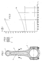
- the connecting rod for an internal combustion engine shown in FIG. 1 consists of a cast part which has a piston pin eye 1, a half crankshaft bearing eye 2 and a connecting rod shaft 3 which connects parts 1 and 2.
- a core 4 is cast, which consists of a material that has a lower specific weight, a smaller linear expansion coefficient and a higher melting point than the casting material.
- the diagram in FIG. 3 shows the change in the linear coefficient of thermal expansion of graphite (C), titanium (Ti), steel (Fe) and a light metal alloy (Al) as a function of the temperature (T). While the thermal expansion of graphite in the area of interest here remains essentially the same up to the solidification temperature of the casting material, which also applies approximately to the ceramic materials specified for the core, increases the coefficient of thermal expansion for the cast material increases to a greater or lesser extent. When the casting material cools below the solidification temperature, which is about 800 ° - 1000 ° C for steel and titanium and about 500 ° C for the light alloy, there is a strong contraction of the casting material, while the coefficient of expansion of the material of the core 4 im remains essentially constant. Since the casting material is prevented from contracting freely by the core 4, a high tensile stress is built up in the casting material, which, as previously described, considerably reduces the maximum pressure load on the connecting rod during operation.
- the casting process should be carried out under at least partial vacuum in order to avoid decomposition of the graphite and, if steel is used as the casting material, to prevent it from carburizing.
Landscapes
- Engineering & Computer Science (AREA)
- General Engineering & Computer Science (AREA)
- Mechanical Engineering (AREA)
- Chemical & Material Sciences (AREA)
- Combustion & Propulsion (AREA)
- Shafts, Cranks, Connecting Bars, And Related Bearings (AREA)
Abstract
Description
Die Pleuelstange einer Brennkraftmaschine wird im Betrieb einer hohen, durch den Zünddruck erzeugten Druckbelastung ausgesetzt. Um ein Ausknicken des Pleuels unter dieser Druckbelastung zu vermeiden, wird der Pleuelschaft in der Regel mit einem I-förmigen Querschnitt ausgeführt. Eine derartige Pleuelstange läßt sich mit verhältnismäßig geringem Aufwand durch Schmieden oder Gießen herstellen. Für höhere Druckbeanspruchungen, beispielsweise in Rennmotoren, werden Pleuelstangen mit einem Pleuelschaft mit H-förmigen Querschnitt verwendet, die eine wesentlich größere Knickfestigkeit haben, jedoch in der Herstellung sehr teuer sind. Bei faserverstärkten Pleuelstangen wird allgemein eine erhöhte Festigkeit erreicht, allerdings ebenfalls unter Inkaufnahme erheblich höherer Herstellungskosten. Eine Steigerung der Knickfestigkeit durch Vergrößerung der Wandstärke des Pleuelschaftes sind schon aus Gewichtsgründen Grenzen gesetzt.The connecting rod of an internal combustion engine is exposed to a high pressure load generated by the ignition pressure during operation. To prevent the connecting rod from buckling under this pressure load, the connecting rod shaft is usually designed with an I-shaped cross section. Such a connecting rod can be produced by forging or casting with relatively little effort. For higher pressure loads, for example in racing engines, connecting rods with a connecting rod shaft with an H-shaped cross section are used, which have a significantly greater resistance to buckling, but are very expensive to manufacture. In the case of fiber-reinforced connecting rods, increased strength is generally achieved, but also at the expense of significantly higher manufacturing costs. There are limits to increasing the buckling strength by increasing the wall thickness of the connecting rod shaft for weight reasons alone.
Bei bekannten Maßnahmen zur Erhöhung der Knickfestigkeit des Pleuels wird im wesentlichen im gleichen Maße auch die Zugfestigkeit erhöht, obgleich die Zugbelastung bei einem Saugmotor nur etwa 1/8 und bei einem Turbomotor nur etwa 1/14 der maximalen Druckbelastung beträgt. Die bekannten Pleuelstangen sind somit in Bezug auf die Zugbelastung außerordentlich überdimensioniert.In known measures for increasing the buckling strength of the connecting rod, the tensile strength is increased substantially to the same extent, although the tensile load in a naturally aspirated engine is only about 1/8 and in a turbo engine only about 1/14 of the maximum pressure load. The known connecting rods are therefore extremely oversized in terms of the tensile load.
Die Erfindung bezieht sich auf eine Pleuelstange für eine Brennkraftmaschine mit einem Gußteil, das ein Kolbenbolzenauge, ein halbes Kurbelwellen-Lagerauge und einen diese verbindenden Pleuelschaft aufweist, in den ein langgestrecker, sich im wesentlichen über die ganze Länge des Pleuelschaftes erstreckender Kern aus einem Material eingegossen ist, der einen kleineren linearen Ausdehnungskoeffizienten, ein geringeres spezifisches Gewicht und einen höheren Schmelzpunkt als das Gußmaterial hat.The invention relates to a connecting rod for an internal combustion engine with a casting, which has a piston pin eye, half a crankshaft bearing eye and a connecting rod shaft connecting them, into which an elongated, the core, which extends essentially over the entire length of the connecting rod shaft, is cast in from a material which has a smaller coefficient of linear expansion, a lower specific weight and a higher melting point than the casting material.
Bei einem bekannten Pleuel der gattungsgemäßen Art (FR-A-2502036) besteht der Kern aus anorganischen Fasern, beispielsweise Fasern aus rostfreiem Stahl oder Kohlefasern, die vor dem Umgießen mit dem Gußmaterial durch ein Kupferlot miteinander verbunden werden, um eine höhere Packungsdichte zur Erhöhung der Festigkeit der Pleuelstange zu erreichen. Hierzu ist eine innige metallogische Verbindung der Kohlefasern mit dem Gußmaterial erforderlich, die durch das Kupferlot und dadurch, daß das Gußmaterial in die Zwischenräume zwischen den Kohlefasern eindringt, verbessert wird. Von der FR-A-2502036 ist zudem bekannt, das Gußteil aus einer Leichtmetall-Legierung (z.B. Aluminium) und das Bauteil aus mit Kupfer verbundenen Graphitfasern herzustellen.In a known connecting rod of the generic type (FR-A-2502036), the core consists of inorganic fibers, for example stainless steel fibers or carbon fibers, which are connected to one another by a copper solder before being cast with the casting material, in order to increase the packing density to increase the To achieve the strength of the connecting rod. This requires an intimate metallogical connection of the carbon fibers to the casting material, which is improved by the copper solder and by the fact that the casting material penetrates into the spaces between the carbon fibers. From FR-A-2502036 it is also known to produce the casting from a light metal alloy (e.g. aluminum) and the component from graphite fibers connected with copper.
Demgegenüber liegt der Erfindung die Aufgabe zu Grunde, eine Pleuelstange der gattungsgemäßen Art zu schaffen, die sich durch ein geringes Gewicht und eine hohe Knickfestigkeit auszeichnet und verglichen mit faserverstärkten Pleuelstangen kostengünstig herstellt werden kann.In contrast, the invention has for its object to provide a connecting rod of the generic type, which is characterized by a low weight and high resistance to kinking and can be manufactured inexpensively compared to fiber-reinforced connecting rods.
Diese Aufgabe wird erfindungsgemäß durch die in den Kennzeichen der unabhängigen Ansprüche 1 bis 3 angegebenen Merkmale gelöst.This object is achieved according to the invention by the features specified in the characterizing parts of independent claims 1 to 3.
Durch den erfindungsgemäßen Vorschlag wird bei der Herstellung der Pleuelstange durch den Kern in dem Gußmaterial eine Zugspannung erzeugt, um welche die im Betrieb auftretende Druckspannung verringert wird. Die Pleuelstange kann somit auf eine niedrigere maximale Druckspannung ausgelegt und entsprechend leichter ausgeführt werden.Through the proposal according to the invention, a tensile stress is generated by the core in the cast material in the manufacture of the connecting rod, by which the compressive stress occurring during operation is reduced. The connecting rod can thus be designed for a lower maximum compressive stress and can therefore be made lighter.
Zu dem erfindungsgemäßen Vorschlag gibt die vorher erwähnte FR-A-2502036 keinerlei Anregung, da Kohlefasern keine Knickfestigkeit haben und daher auch nicht in der Lage sind, Druckspannungen aufzunehmen und Zugspannungen zu erzeugen. Darüber hinaus hat das Eindringen von Gußmaterial in die Zwischenräume zwischen den Kohlefasern zur Folge, daß sich dieses Gußmaterial beim Abkühlen genauso zusammenzieht wie das den Kern umhüllende Gußmaterial. Es ist daher nicht vorstellbar, daß sich in dem umhüllenden Gußmaterial eine Zugspannung aufbauen könnte.FR-A-2502036 does not provide any suggestion for the proposal according to the invention, since carbon fibers have no kink resistance and are therefore not able to absorb compressive stresses and tensile stresses produce. In addition, the penetration of casting material into the spaces between the carbon fibers has the consequence that this casting material contracts in the same way as the casting material enveloping the core. It is therefore not conceivable that tensile stress could build up in the enveloping casting material.
Die Herstellung der erfindungsgemäßen Pleuelstange erfolgt in üblicher Weise dadurch, daß der Kern in die Form eingelegt und dann mit dem Gußmaterial umgossen wird. Bei der Verwendung von Stahl als Gußmaterial wird der Kern dabei auf etwa 500 - 700° erwärmt und dehnt sich entsprechend aus. Das flüssige Gußmaterial kühlt sich ab und nach dem Erreichen der Erstarrungstemperatur beginnt duch das Zusammenziehen des erstarrenden Gußmaterials eine Druckbeaufschlagung des Kerns. Da der Ausdehnungskoeffizient des Kerns kleiner ist als der des Gußmaterials, kann sich das Gußmaterial nicht frei zusammenziehen und es bauen sich in ihm Zugspannungen auf. Bei der Druckbelastung durch die Zündkräfte im Betrieb werden zunächst diese Zugspannungen abgebaut, bevor die Pleuelstange auf Druck beansprucht wird. Damit kann die Auslegung der Pleuelstange nach den resultierenden Druckkräften erfolgen, die kleiner sind als bei der üblichen Auslegung. Durch entsprechende Wahl der Werkstoffe für das Gußmaterial und den Kern lassen sich bei der Herstellung der erfindungsgemäßen Pleuelstange in dem Gußmaterial Zugspannungen erzeugen, die bis zu 60 % der in Betrieb auftretenden maximalen Druckspannungen betragen können. Der Pleuelschaft braucht dann nur auf etwa 40 % der im Betrieb auftretenden maximalen Druckspannung ausgelegt zu werden, was bei einer Pleuelstange mit gleicher Knickfestigkeit zu einer Gewichtseinsparung von bis zu 60 % für den Pleuelschaft führen kann. Dies gilt für eine Materialpaarung mit Titan als Gußmaterial und Graphit als Material für den Kern. Bei Stahl als Gußmaterial und Graphit für den Kern läßt sich eine Gewichtsreduzierung von mindestens 20 - 30 % für den Pleuelschaft erreichen.The connecting rod according to the invention is produced in a conventional manner by inserting the core into the mold and then casting the casting material around it. When using steel as the casting material, the core is heated to approximately 500-700 ° and expands accordingly. The liquid casting material cools down and after the solidification temperature has been reached, the contraction of the solidifying casting material begins to pressurize the core. Since the coefficient of expansion of the core is smaller than that of the casting material, the casting material cannot contract freely and tensile stresses build up in it. When the ignition forces are subjected to pressure during operation, these tensile stresses are reduced before the connecting rod is subjected to pressure. This allows the connecting rod to be designed according to the resulting compressive forces, which are smaller than with the conventional design. By appropriate selection of the materials for the casting material and the core, tensile stresses can be generated in the casting material in the production of the connecting rod according to the invention, which can amount to up to 60% of the maximum compressive stresses occurring during operation. The connecting rod shaft then only needs to be designed for around 40% of the maximum compressive stress occurring during operation, which can lead to a weight saving of up to 60% for the connecting rod shaft with a connecting rod with the same kink resistance. This applies to a material combination with titanium as the casting material and graphite as the material for the core. For steel as a casting material and graphite for the The core can achieve a weight reduction of at least 20-30% for the connecting rod.
Wird beispielsweise als maximale Druckbelastung der Pleuelstange durch den Zünddruck ein Wert von 5 t angenommen und beträgt die Zugbelastung durch die Massenbeschleunigungskräfte in OT 1 t und wird durch den Kern in dem Gußmaterial eine Zugspannung von 2 t erzeugt, so verringert sich die maximale Druckbelastung auf 3 t, während die Zugbelastung auf ebenfalls 3 t steigt. Dadurch kann die Masse des Gußmaterials um 40 % verringert werden. Das Gewicht der Pleuelstange wird zwar durch das Gewicht des Kerns erhöht. Da das Material des Kerns jedoch eine erheblich geringere Wichte hat, ergibt sich insgesamt eine Gewichtseinsparung von etwa 20 - 30 %.If, for example, a value of 5 t is assumed as the maximum pressure load on the connecting rod due to the ignition pressure and the tensile load due to the mass acceleration forces in TDC is 1 t and a tensile stress of 2 t is generated by the core in the cast material, the maximum pressure load is reduced to 3 t, while the tensile load also increases to 3 t. This enables the mass of the casting material to be reduced by 40%. The weight of the connecting rod is increased by the weight of the core. However, since the material of the core has a significantly lower weight, there is an overall weight saving of about 20-30%.
Als Gußmaterial kommt in erster Linie Stahl, Titan oder eine Leichtmetallegierung in Frage. Bevorzugte Werkstoffe für den Kern sind Graphit und keramische Stoffe, insbesondere Sinterkörper aus Bornitrid, Siliziumnitrid, Siliziumcarbid und Aluminiumtitanat (Al₂TiO₅) sowie für den Fall, daß Stahl als Gußmaterial verwendet wird, auch Titan. In der nachfolgenden Tabelle sind die für die Erfindung maßgeblichen Kennwerte dieser Werkstoffe aufgeführt.![]()
![]()


- αα
- = linearer Ausdehnungskoeffizient= coefficient of linear expansion
- γγ
- = Wichte= Weights
- Ts T s
- = Schmelztemperatur= Melting temperature
Aus der Tabelle ist ersichtlich, daß Graphit aufgrund seines kleinen linearen Ausdehnungskoeffizienten und seiner geringen Wichte ein bevorzugter Werkstoff für den Kern ist, da er einerseits in dem Gußmaterial eine hohe Zugspannung erzeugen kann und andererseits das Gewicht des Gußteils nur wenig erhöht. Die angegebenen Keramikwerkstoffe sind jedoch gleichermaßen für die angegebenen Gußwerkstoffe geeignet. Bei Stahl als Gußwerkstoff ist für den Kern auch Titan möglich, dessen Ausdehnungskoeffizient und dessen Wichte erheblich geringer sind als diejenigen von Stahl.From the table it can be seen that graphite is a preferred material for the core due to its small coefficient of linear expansion and its low weight, since on the one hand it can generate a high tensile stress in the casting material and on the other hand only slightly increases the weight of the casting. However, the specified ceramic materials are equally suitable for the specified casting materials. With steel as the casting material, titanium is also possible for the core, the coefficient of expansion and weight of which are considerably lower than those of steel.
Ein Ausführungsbeipiel der Erfindung wird im folgenden unter Bezugnahme auf die Zeichnungen beschrieben. Es zeigt:
- Fig. 1 einen Längsschnitt eines erfindungsgemäßen Pleuels,
- Fig. 2 einen Schnitt entlang Linie 2-2 in Figur 1 und
- Fig. 3 ein Diagramm, aus dem die Wärmedehnung der vorstehend erwähnten Werkstoffe in Abhängigkeit von der Temperatur dargestellt sind.
- 1 shows a longitudinal section of a connecting rod according to the invention,
- Fig. 2 shows a section along line 2-2 in Figure 1 and
- Fig. 3 is a diagram showing the thermal expansion of the above mentioned materials are shown depending on the temperature.
Die in Figur 1 dargestellte Pleuelstange für eine Brennkraftmaschine besteht aus enem Gußteil, das ein Kolbenbolzenauge 1, ein halbes Kurbelwellen-Lagerauge 2 und einen Pleuelschaft 3 aufweist, der die Teile 1 und 2 verbindet. In dem Pleuelschaft 3 ist ein Kern 4 eingegossen, der aus einem Material besteht, das ein geringeres spezifisches Gewicht, einen kleineren linearen Ausdehnungskoeffizienten und einen höheren Schmelzpunkt als das Gußmaterial hat.The connecting rod for an internal combustion engine shown in FIG. 1 consists of a cast part which has a piston pin eye 1, a half
Bei der Herstellung der Pleuelstange durch Umgießen des Kerns 4 in einer Form werden aufgrund des geringeren Ausdehnungskoeffizienten des Materials des Kerns 4 in dem den Pleuelschaft 3 bildenden Gußmaterial Zugspannungen aufgebaut. Bei der im Betrieb stattfindenden Druckbelastung der Pleuelstange durch die Zünddrücke wird zunächst diese Zugspannung abgebaut, bevor die Pleuelstange auf Druck beansprucht wird. Die maximale Druckbelastung, für die die Pleuelstange ausgelegt werden muß, ist somit um den Betrag dieser bei der Herstellung erzeugten Zugspannung verringert. Entsprechend kann die Masse und damit das Gewicht des den Pleuelschaft 3 bildenden Gußmaterials verringert werden.In the production of the connecting rod by casting around the
Das Diagramm von Figur 3 zeigt die Änderung des linearen Wärmedehnungskoeffizienten von Graphit (C), Titan (Ti), Stahl (Fe) und einer Leichtmetallegierung (Al) in Abhängigkeit von der Temperatur (T). Während die Wärmedehnung von Graphit in dem hier interessierenden Bereich bis zur Erstarrungstemperatur des Gußmaterials im wesentlichen gleich bleibt, was im übrigen auch in etwa für die angegebenen keramischen Werkstoffe für den Kern gilt, steigt der Wärmedehnungskoeffizient für das Gußmaterial mehr oder weniger stark an. Bei der Abkühlung des Gußmaterials unter die Erstarrungstemperatur, die für Stahl und Titan bei etwa 800° - 1000° C und für die Leichtmetallegierung bei etwa 500° C liegt, findet eine starke Zusammenziehung des Gußmaterials statt, während der Ausdehnungskoeffizient des Werkstoffes des Kerns 4 im wesentlichen konstant bleibt. Da das Gußmaterial durch den Kern 4 daran gehindert ist, sich frei zusammenzuziehen, wird in dem Gußmaterial eine hohe Zugspannung aufgebaut, wodurch, wie vorher beschrieben, die maximale Druckbelastung der Pleuelstange im Betrieb erheblich reduziert wird.The diagram in FIG. 3 shows the change in the linear coefficient of thermal expansion of graphite (C), titanium (Ti), steel (Fe) and a light metal alloy (Al) as a function of the temperature (T). While the thermal expansion of graphite in the area of interest here remains essentially the same up to the solidification temperature of the casting material, which also applies approximately to the ceramic materials specified for the core, increases the coefficient of thermal expansion for the cast material increases to a greater or lesser extent. When the casting material cools below the solidification temperature, which is about 800 ° - 1000 ° C for steel and titanium and about 500 ° C for the light alloy, there is a strong contraction of the casting material, while the coefficient of expansion of the material of the
Welche Materialpaarung gewählt wird, hängt von der Art der Brennkraftmaschine ab, für welche die.Pleuelstange bestimmt ist. Bei Rennmotoren, die normalerweise mit sehr hoher Drehzahl laufen, ist die im Betreib auftretende Zugspannung verhältnismäßig hoch, so daß man eine Materialpaarung wählen wird, mit der bei der Herstellung der Pleuelstange in dem Gußmaterial eine geringere Zugspannung induziert wird als bei einer Pleuelstange für einen Serienmotor, bei dem aufgrund der niedrigeren Drehzahlen der im Betreib auftretende Unterschied zwischen Zug- und Druckbelastung größer ist.Which material pairing is selected depends on the type of internal combustion engine for which the connecting rod is intended. In racing engines, which normally run at a very high speed, the tensile stress that occurs during operation is relatively high, so that one will choose a material pair with which a lower tensile stress is induced in the cast material during the production of the connecting rod than in the case of a connecting rod for a series engine , in which the difference between tensile and compressive loads occurring in operation is greater due to the lower speeds.
Wird als Material für den Kern 4 Graphit gewählt, so sollte der Gießvorgang unter zumindest teilweisem Vakuum erfolgen, um eine Zersetzung des Graphits und bei der Verwendung von Stahl als Gußmaterial ein Aufkohlen desselben zu vermeiden.If graphite is selected as the material for the
Claims (3)
- Connecting rod for an internal combustion engine, with a casting which comprises a piston pin boss (1), a halfboss (2) for a crankshaft bearing and a connecting rod shank (3), which connects these two parts and into which an elongate core (4), which extends essentially over the entire length of the connecting rod shank (3), is cast, which core consists of a material having a lower coefficient of linear expansion, a lower relative density and a higher melting point than the casting material, characterised in that the casting consists of steel, and that a compression-proof body of graphite, a ceramic material, aluminium titanate, titanium or a nitride, preferably boron nitride or silicon nitride, is used as the core (4) to produce a tensile stress in the casting during manufacture.
- Connecting rod for an internal combustion engine, with a casting which comprises a piston pin boss (1), a halfboss (2) for a crankshaft bearing and a connecting rod shank (3), which connects these two parts and into which an elongate core (4), which extends essentially over the entire length of the connecting rod shank (3), is cast, which core consists of a material having a lower coefficient of linear expansion, a lower relative density and a higher melting point than the casting material, characterised in that the casting consists of titanium, and that a compression-proof body of graphite, a ceramic material, aluminium titanate or a nitride, preferably boron nitride or silicon nitride, is used as the core to produce a tensile stress in the casting during manufacture.
- Connecting rod for an internal combustion engine, with a casting of a light metal alloy which comprises a piston pin boss (1), a half-boss (2) for a crankshaft bearing and a connecting rod shank (3), which connects these two parts and into which an elongate core (4), which extends essentially over the entire length of the connecting rod shank (3), is cast, which core consists of a material having a lower coefficient of linear expansion, a lower relative density and a higher melting point than the casting material, characterised in that a compression-proof body of graphite or boron nitride is used as the core to produce a tensile stress in the casting during manufacture.
Applications Claiming Priority (2)
| Application Number | Priority Date | Filing Date | Title |
|---|---|---|---|
| DE3843954 | 1988-12-24 | ||
| DE3843954A DE3843954A1 (en) | 1988-12-24 | 1988-12-24 | CONNECTING ROD |
Publications (2)
| Publication Number | Publication Date |
|---|---|
| EP0452343A1 EP0452343A1 (en) | 1991-10-23 |
| EP0452343B1 true EP0452343B1 (en) | 1993-09-15 |
Family
ID=6370306
Family Applications (1)
| Application Number | Title | Priority Date | Filing Date |
|---|---|---|---|
| EP90900158A Expired - Lifetime EP0452343B1 (en) | 1988-12-24 | 1989-12-12 | Connecting rod |
Country Status (3)
| Country | Link |
|---|---|
| EP (1) | EP0452343B1 (en) |
| DE (2) | DE3843954A1 (en) |
| WO (1) | WO1990007654A1 (en) |
Families Citing this family (4)
| Publication number | Priority date | Publication date | Assignee | Title |
|---|---|---|---|---|
| DE4332444B4 (en) * | 1993-09-23 | 2006-06-01 | Bayerische Motoren Werke Ag | Machine part of a light metal casting alloy, in particular connecting rod for reciprocating engines |
| IT1284366B1 (en) * | 1996-02-02 | 1998-05-18 | Embraco Europ Srl | CONNECTING ROD FOR SMALL ALTERNATIVE MACHINES, SUCH AS COMPRESSORS FOR REFRIGERATORS, AND ALTERNATIVE MACHINE INCORPORATING THIS CONNECTING ROD. |
| DE19752753A1 (en) * | 1997-11-28 | 1999-06-02 | Bayerische Motoren Werke Ag | Method for breaking a bearing cap in a connecting rod for reciprocating piston machines |
| DE19753358C2 (en) * | 1997-12-02 | 2000-05-11 | Daimler Chrysler Ag | Connecting rod for a reciprocating piston machine and process for its manufacture |
Family Cites Families (6)
| Publication number | Priority date | Publication date | Assignee | Title |
|---|---|---|---|---|
| DE1287868B (en) * | ||||
| US3698264A (en) * | 1970-12-28 | 1972-10-17 | Bertea Corp | Composite rod |
| GB1460528A (en) * | 1974-05-15 | 1977-01-06 | Toyota Motor Co Ltd | Method for producing a metal and ceramic composite |
| JPS5631537A (en) * | 1979-08-17 | 1981-03-30 | Honda Motor Co Ltd | Connecting rod for internal combustion engine |
| JPS57155336A (en) * | 1981-03-20 | 1982-09-25 | Honda Motor Co Ltd | Production of fiber-reinforced composite body |
| DE3248373C2 (en) * | 1982-12-28 | 1985-03-21 | Honda Giken Kogyo K.K., Tokio/Tokyo | connecting rod |
-
1988
- 1988-12-24 DE DE3843954A patent/DE3843954A1/en not_active Withdrawn
-
1989
- 1989-12-12 EP EP90900158A patent/EP0452343B1/en not_active Expired - Lifetime
- 1989-12-12 WO PCT/EP1989/001521 patent/WO1990007654A1/en active IP Right Grant
- 1989-12-12 DE DE90900158T patent/DE58905648D1/en not_active Expired - Fee Related
Also Published As
| Publication number | Publication date |
|---|---|
| WO1990007654A1 (en) | 1990-07-12 |
| EP0452343A1 (en) | 1991-10-23 |
| DE58905648D1 (en) | 1993-10-21 |
| DE3843954A1 (en) | 1990-06-28 |
Similar Documents
| Publication | Publication Date | Title |
|---|---|---|
| DE3610856A1 (en) | COMPOSITE METAL CAST ITEM | |
| EP0504780B1 (en) | Piston for a hydrostatic axial and radial pistonmachine and method for constructing such a piston | |
| DE3009656C2 (en) | Method for manufacturing a camshaft | |
| DE3500653C2 (en) | ||
| EP0184864B1 (en) | Cast construction parts for internal-combustion engines incorporating reinforcing elements, and method for producing the connection between the parts and the elements | |
| DE2952117B1 (en) | Piston pin | |
| DE2644272A1 (en) | METHOD AND APPARATUS FOR MANUFACTURING FIBER-REINFORCED PRODUCTS | |
| EP2165790A1 (en) | Method for producing a workpiece from composite material and workpiece made of composite material | |
| DE2548201A1 (en) | PROCESS FOR MANUFACTURING HEADED SHAFT PARTS FROM HIGH STRENGTH TWO-PHASE TITANIUM ALLOYS | |
| EP0452343B1 (en) | Connecting rod | |
| EP0153473B1 (en) | Cast aluminium pistons for internal-combustion engines with a mechanically densified surface of the pin bores | |
| EP0186695A1 (en) | Hollow shaft | |
| DE3810497C2 (en) | Process for producing an aluminum alloy with excellent kneadability | |
| DE3722437A1 (en) | PISTON PISTON ASSEMBLY | |
| DE2711810A1 (en) | ROLLER STRUCTURE | |
| DE3600140A1 (en) | METHOD AND DEVICE FOR PRESSURE TRANSFER | |
| DE3619555C2 (en) | Process for producing a metal-ceramic composite body and its use | |
| DE60205198T2 (en) | Bearing device for vehicle transmission | |
| DE10206728B4 (en) | Hollow piston and method for its production by sintering | |
| EP1349634B1 (en) | Filtering candle comprising a sintered filtering tube | |
| DE3018345A1 (en) | METHOD FOR PRODUCING A THREAD-ROLLED SINTERED CYLINDRICAL METAL PRODUCT | |
| DE19916566B4 (en) | Matrix for highly stressed hollow molds | |
| WO2000011367A1 (en) | Synchronizing device for a gearbox | |
| DE3939261A1 (en) | Elongated part e.g. connecting rod with core and cast covering - has compression resistant e.g. sintered material core with clamping pins extending into outer steel cover | |
| EP0593691B1 (en) | Process for producing sintered components |
Legal Events
| Date | Code | Title | Description |
|---|---|---|---|
| PUAI | Public reference made under article 153(3) epc to a published international application that has entered the european phase |
Free format text: ORIGINAL CODE: 0009012 |
|
| 17P | Request for examination filed |
Effective date: 19910425 |
|
| AK | Designated contracting states |
Kind code of ref document: A1 Designated state(s): DE FR GB |
|
| 17Q | First examination report despatched |
Effective date: 19920723 |
|
| GRAA | (expected) grant |
Free format text: ORIGINAL CODE: 0009210 |
|
| AK | Designated contracting states |
Kind code of ref document: B1 Designated state(s): DE FR GB |
|
| REF | Corresponds to: |
Ref document number: 58905648 Country of ref document: DE Date of ref document: 19931021 |
|
| GBT | Gb: translation of ep patent filed (gb section 77(6)(a)/1977) |
Effective date: 19930927 |
|
| ET | Fr: translation filed | ||
| PLBE | No opposition filed within time limit |
Free format text: ORIGINAL CODE: 0009261 |
|
| STAA | Information on the status of an ep patent application or granted ep patent |
Free format text: STATUS: NO OPPOSITION FILED WITHIN TIME LIMIT |
|
| 26N | No opposition filed | ||
| PGFP | Annual fee paid to national office [announced via postgrant information from national office to epo] |
Ref country code: GB Payment date: 19961118 Year of fee payment: 8 |
|
| PGFP | Annual fee paid to national office [announced via postgrant information from national office to epo] |
Ref country code: DE Payment date: 19961206 Year of fee payment: 8 |
|
| PGFP | Annual fee paid to national office [announced via postgrant information from national office to epo] |
Ref country code: FR Payment date: 19961216 Year of fee payment: 8 |
|
| PG25 | Lapsed in a contracting state [announced via postgrant information from national office to epo] |
Ref country code: GB Free format text: LAPSE BECAUSE OF NON-PAYMENT OF DUE FEES Effective date: 19971212 |
|
| PG25 | Lapsed in a contracting state [announced via postgrant information from national office to epo] |
Ref country code: FR Free format text: THE PATENT HAS BEEN ANNULLED BY A DECISION OF A NATIONAL AUTHORITY Effective date: 19971231 |
|
| GBPC | Gb: european patent ceased through non-payment of renewal fee |
Effective date: 19971212 |
|
| PG25 | Lapsed in a contracting state [announced via postgrant information from national office to epo] |
Ref country code: DE Free format text: LAPSE BECAUSE OF NON-PAYMENT OF DUE FEES Effective date: 19980901 |
|
| REG | Reference to a national code |
Ref country code: FR Ref legal event code: ST |