EP0452133B1 - Polymer coated lamps and their production - Google Patents
Polymer coated lamps and their production Download PDFInfo
- Publication number
- EP0452133B1 EP0452133B1 EP91303221A EP91303221A EP0452133B1 EP 0452133 B1 EP0452133 B1 EP 0452133B1 EP 91303221 A EP91303221 A EP 91303221A EP 91303221 A EP91303221 A EP 91303221A EP 0452133 B1 EP0452133 B1 EP 0452133B1
- Authority
- EP
- European Patent Office
- Prior art keywords
- layer
- metal oxide
- oxide grains
- lamp
- envelope
- Prior art date
- Legal status (The legal status is an assumption and is not a legal conclusion. Google has not performed a legal analysis and makes no representation as to the accuracy of the status listed.)
- Expired - Lifetime
Links
Images


Classifications
-
- H—ELECTRICITY
- H01—ELECTRIC ELEMENTS
- H01J—ELECTRIC DISCHARGE TUBES OR DISCHARGE LAMPS
- H01J61/00—Gas-discharge or vapour-discharge lamps
- H01J61/02—Details
- H01J61/30—Vessels; Containers
- H01J61/35—Vessels; Containers provided with coatings on the walls thereof; Selection of materials for the coatings
-
- H—ELECTRICITY
- H01—ELECTRIC ELEMENTS
- H01J—ELECTRIC DISCHARGE TUBES OR DISCHARGE LAMPS
- H01J5/00—Details relating to vessels or to leading-in conductors common to two or more basic types of discharge tubes or lamps
- H01J5/02—Vessels; Containers; Shields associated therewith; Vacuum locks
- H01J5/03—Arrangements for preventing or mitigating effects of implosion of vessels or containers
Definitions
- the present invention relates to a lamp having a layer, which is made of fluorocarbon polymer, coated on an envelope thereof, and also relates to a method for forming the layer.
- a lamp having a layer, which is made of fluorocarbon polymer, coated on a glass envelope of the lamp is known in this field.
- the layer is formed so as to prevent glass pieces of the glass envelope from scattering when the glass envelope of the lamp is broken.
- the fluorocarbon polymer is used as a material of the layer since the fluorocarbon polymer has a high melting temperature. Therefore, the layer of the fluorocarbon polymer is adapted especially to high intensity discharge lamps such as metal halide lamps whose outer envelopes have high temperature of more than 200 °C.
- EP-A-0175 333 discloses an electric lamp including a containment coating consisting of a perfluoroalkoxy resin which has a continuous service temperature rating of about 260°C.
- the conventional layer of the fluorocarbon polymer is not sufficient in its strength for high intensity discharge lamps. Therefore there is a demand to increase the strength of the layer of the fluorocarbon polymer on the outer glass envelope of the high intensity discharge lamp.
- a strengthened layer of the fluorocarbon polymer is obtained by way of increasing the thickness of the layer of the fluorocarbon polymer.
- the lamp has a shortcoming in that the luminous flux of the lamp emitted from the outer glass envelope of the lamp decreases, because of light absorption by the layer of the fluorocarbon polymer.
- FIG. 60-71546 Further lamps having an improved layer of the fluorocarbon polymer are shown in the Japanese Patent Laid Open Publications No. 60-71546 and No. 64-21855.
- the lamp shown in the 60-71546 publication has a layer of fluorocarbon polymer containing glass fibers. But the glass fibers are mixed into the fluorocarbon polymer for increasing the adhensive strength between the layer of the fluorocarbon polymer and the outer glass envelope of the lamp, and not for increasing the strength of the layer of the fluorocarbon polymer itself, in other words not for tensile strength.
- the layer of the fluorocarbon polymer of this lamp is not improved in its tensile strength.
- the lamp shown in the 64-21855 publication has an under layer between the layer of the fluorocarbon polymer and the outer glass envelope of the lamp.
- the under layer is generally called a primer layer.
- the under layer shown in the 64-21855 publication contains metal oxide grains dispersed therein and is coated for the same reason as the glass fibers mixed into the fluorocarbon polymer.
- the layer of the fluorocarbon polymer of this lamp is not improved in its strength.
- the lamp according to the present invention comprises: means for emitting light and heat; an envelope surrounding said means and heated at more than 200 °C by said means; and an first layer coated on the ouside of said envelope, said layer comprising a fluorocarbon polymer containing metal oxide grains dispersed therein.
- Fig. 1 is a front view of a metal halide lamp according to the first embodiment of the present invention.
- the metal halide lamp has an outer envelope 11 made of hard glass.
- the outer envelope 11 forms a shape, so called BT-shape, swelling around a centre thereof and forms thin portions at both ends of the outer envelope 11 as compared with a portion around the centre of the outer envelope 11.
- One thin portion is a neck portion 13 and the other is a top portion 15.
- the neck portion 13 has a base 17 for attaching the lamp to lighting equipment (not shown) and for recieving electric power.
- the outer envelope 11 includes an inner tube 19 therein
- the inner tube 19 is made of quartz glass.
- a pair of electrodes 21 and 22 are provided at both ends in the inner tube 19.
- a rare gas as a starting gas such as argon and a discharge gas such as may be derived from mercury, sodium halide and scandium halide are sealed in the inner tube 19.
- the inner tube 19 is supported in the outer envelope 11 by a pair of supporting wires 23 and 25 and a pair of insulated holders 27 and 29.
- the one supporting wire 23 is fixed by elastic members 31 and 31 at the top portion 15 and the other supporting wire 25 is connected with and supported by the lead wire 33 which is mounted to a stem portion 37.
- the electrode 21 is connected electrically with the other lead wire 35 through a connecting wire 38.
- the other electrode 22 is connected electrically with the other supporting wire 25.
- Both of the lead wires 33 and 35 are connected electrically with the base 17. Accordingly, both of electrodes 21 and 22 are are connected electrically with the base 17.
- An overcoated layer 39 is coated on an outside outer glass envelope 11 shown in Fig. 2 which indicates a partial sectional view of the outer glass envelope 11 of the lamp.
- the overcoated layer 39 essentially consists of fluorocarbon polymer containing metal oxide grains (not shown) dispersed therein and has a thickness of about 100 ⁇ m.
- An undercoated layer 41 is formed between the overcoated layer 39 and the outer surface of the outer glass envelope 11.
- the fluorocarbon polymer of this embodiment essentially consists of tetrafluoroethylene - perfluoroalkylvinylether copolymer (called PFA) (MP-103: available from MITSUI DUPONT FLUOROCHEMICAL CO., LTD in Japan), but other fluorocarbon polymers, for example tetrafluoroethylene - hexafluoropropylene copolymer (called FEP), tetrafluoroethylene - hexafluoropropylene - perfluoroalkylvinylether copolymer (called EPE) (available from MITSUI DUPONT FLUOROCHEMICAL CO., LTD in Japan) and so on, may be used.
- PFA tetrafluoroethylene - perfluoroalkylvinylether copolymer
- FEP tetrafluoroethylene - hexafluoropropylene copolymer
- EPE tetrafluor
- the metal oxide grains of this embodiment consist of zinc oxide (ZnO) (available from SUMITOMO SEMENTO CO., LTD in Japan) and titanium oxide (TiO2) (available from SUMITOMO SEMENTO CO., LTD in Japan), but other metal oxide, for example tantalum oxide (Ta2O5), silicon oxide (SiO2), alminium oxide (Al2O3) and so on, may be used.
- the weight of metal oxide grains is 1 % by weight of fluorocarbon polymer.
- An average particle size of grains of zinc oxide (ZnO) and titanium oxide (TiO2) is about 0.02 ⁇ m, and the weight of zinc oxide (ZnO) and the weight of titanium oxide (TiO2) are the same as each other.
- the undercoated layer 41 is formed by coating a mixed agent, generally called a primer, of a noionic surface active agent (458-500: available from MITSUI DUPONT FLUOROCHEMICAL CO., LTD in Japan), a certain amount of silicon oxide (SiO2) grains and alminium oxide (Al2O3) grains on the outer surface of the outer glass envelope 11 and drying the coated agent. It is necessary to eliminate fats and oils from the outer surface of the outer glass envelope 11, for example, by washing or baking before coating the mixed agent.
- a mixed agent generally called a primer
- a noionic surface active agent (458-500: available from MITSUI DUPONT FLUOROCHEMICAL CO., LTD in Japan
- SiO2 silicon oxide
- Al2O3 alminium oxide
- the overcoated layer 39 is formed by steps including a well known electrostatic coating method.
- the first step is preparing a mixed powder containing the powder of the fluorocarbon polymer, the powder of zinc oxide (ZnO) grains and the powder of titanium oxide (TiO2) grains. The detail of each powder is described above.
- the next step is coating the mixed powder on the surface of the undercoated layer 41 in an area of the undercoated layer 41 by the electrostatic coating method. In this case, the undercoated layer 41 works as an electrode attracting charged particles of powder. Therefore, the overcoated layer 39 is formed only on the undercoated layer 41.
- the next step is heating the powder coated on the surface of the outer glass envelope 11 at a temperature of 310 °C to 400 °C in order that the powder of the fluorocarbon polymer melts and forms a continuous layer of the fluorocarbon polymer, i.e. the overcoated layer 39.
- the undercoated layer 41 is coated not only in order to increase the adhesive strength of the overcoated layer 39 with respect to the outer surface of the outer glass envelope 11 but also in order to form the overcoated layer 39.
- the overcoated layer 39 has an even density of the metal oxide grains at any position thereof because the above described method does not use liquid, and is not wet coating. Therefore the metal oxide grains do not collect or aggregate unevenly during forming of the overcoated layer 39.
- the above described method does not have the disadvantage that the metal oxide grains would collect at one side of the envelope during drying of the coating liquid because of the effect of gravity.
- the overcoated layer 39 has an even thickness at any position thereof since the above described method does not use liquid and therefore does not have the defect that coating liquid would flow and drop toward one side of the envelope during the step for drying the coating liquid.
- Fig. 3 shows measured results of tensile strength of the overcoated layer 39 of the lamps when the weight ratio of the metal oxide grains dispersed in the overcoated layer 39 is varied.
- a horizontal axis indicates the weight ratio of the metal oxide grains and a vertical axis indicates relative value of the tensile strength of the overcoated layer 39, and 100% means the tensile strength in case of the overcoated layer 39 without the metal oxide grains.
- an average particle size of the metal oxide grains is 0.02 ⁇ m and the thickness of the overcoated layer 39 is about 100 ⁇ m.
- the tensile strength increased, accompanied by an incease of the weight ratio of the metal oxide grains in the range of more than 0.05% of the metal oxide grains.
- the reason why the tensile strength increased is thought to be that the metal oxide grains dispersed between overlapped fluorocarbon polymer molecules of the overcoated layer 39 prevent slipping between fluorocarbon polymer molecules. Moreover, the following is supposed. As the overcoated layer 39 formed by the above described method has the even density of the metal oxide grains at any position thereof and there is no position that has extremely low density of the metal oxide grains, there is no position that has an extremely weak tensile strength as compared with other positions. It is thought that the tensile strength increased because of the above described reason.
- Fig. 4 shows measured results of luminous flux of the lamps, varing the weight ratio and the average particle size of the metal oxide grains dispersed in the overcoated layer 39.
- a horizontal axis indicates the weight ratio of the metal oxide grains and a vertical axis indicates relative value of the luminous flux of the lamps, and 100% means the luminous flux of the lamps in case that the overcoated layer 39 does not have the metal oxide grains.
- the three lines (a), (b) and (c) correspond to the average particle size of 0.02 ⁇ m, 0.1 ⁇ m and 0.2 ⁇ m respectively.
- the luminous flux decreased, accompanied by an increase of the weight ratio of the metal oxide grains.
- the metal oxide grains of the overcoated layer 39 absorb the light.
- the decrease of the luminous flux was not so much within the range of 3 % of the weight ratio of the metal oxide grains, but it was too much beyond the range of 3 % of the weight ratio of the metal oxide grains. It is also understood that the decrease of the luminous flux was too much when the particle size was more than 0.1 ⁇ m even if the weight ratio of the metal oxide grains was small.
- the overcoated layer 39 may have the defects of opacity or non-transparency.
- the preferable range of the particle size of the metal oxide grains was determined to be not more than 0.1 ⁇ m and the preferable range of the weight ratio of the metal oxide grains was determined to be from 0.05 to 3 %.
- Fig. 5 shows measured results of intensity of ultraviolet rays emitted from the lamps, varying the weight ratio (M wt%) of the metal oxide grains dispersed in the overcoated layer 39 and the thickness (t ⁇ m) of the overcoated layer 39.
- the metal oxide grains of the lamps comprise titanium oxide (TiO2) and zinc oxide (ZnO) as described above.
- a horizontal axis indicates an amount (Mxt) of the metal oxide grains dispersed in the overcoated layer 39.
- the amount (Mxt) of the metal oxide grains dispersed in the overcoated layer 39 is defined as a multiple of the weight ratio (M) of the metal oxide grains and the thickness (t) of the overcoated layer 39.
- a vertical axis indicates relative intensity of UVB emitted from the lamps and 100 % means the intensity of UVB where the overcoated layer 39 does not contain the metal oxide grains.
- the intensity of UVB emitted from the lamp decreased, accompanied by an increase of the weight ratio (M) of the metal oxide grains and the thickness (t) of the overcoated layer 39.
- the intensity of UVB emitted from the lamp which has, as described above, 100 ⁇ m thickness of the overcoated layer 39 containing 1 % weight of the metal oxide grains of titanium oxide (TiO2) and zinc oxide (ZnO) decreases under a hundredth as much as the intensity of UVB emitted from the lamp having the overcoated layer 39 not containing the metal oxide grains.
- Fig. 6 shows the relation between luminous flux of the lamp and the amount (M ⁇ t) of the metal oxide grains.
- a horizontal axis indicates the amount (M ⁇ t) of the metal oxide grains and a vertical axis indicates relative value of the luminous flux of the lamp, and 100 % means the luminous flux of the lamp whose overcoated layer 39 does not have the metal oxide grains, or 100 % means the luminous flux of the lamp which does not have the overcoated layer 39.
- Fig. 6 was obtained under the condition that the metal oxide grains consisted of the same amounts of titanium oxide (TiO2) and zinc oxide (ZnO) which had an average particle size of about 0.02 ⁇ m and that the overcoated layer 39 had a thickness of about 100 ⁇ m.
- the intensity of the luminous flux emitted from the lamp decreased, accompanied by an increase of the weight ratio (M) of the metal oxide grains and the thickness (t) of the overcoated layer 39.
- M weight ratio
- t thickness
- the decrease of the luminous flux was not so much within 300 (wt% ⁇ ⁇ m) of the amount of the metal oxide grains, but it was too much beyond 300 (wt% ⁇ ⁇ m) of the amount of the metal oxide grains.
- the overcoated layer 39 may have defects of opacity or non-transparency where the amount (M ⁇ t) of the metal oxide grains is beyond 300 (wt% ⁇ ⁇ m), the same as the results according to Fig. 4.
- the preferred amount of the metal oxide grains satisfies the following relationship: 5 ⁇ M ⁇ t ⁇ 300
- Fig. 7 and Fig.8 show a second embodiment of the present invention.
- the same numerals are applied to the similar elements to the first embodiment, and therefore detailed description thereof is not repeated.
- the weight ratio (or density) of the metal oxide grains of the overcoated layer 39 of the lamp of this embodiment varies according to positions of the overcoated layer 39. This is the only difference between the lamp of this embodiment and the lamp of the first embodiment.
- the weight ratio of the metal oxide grains of the overcoated layer 39a is 0.75 wt% at the top side area A of the lamp including the top portion 15 of the envelope 11, and the weight ratio of the metal oxide grains of the overcoated layer 39b is 1 wt% at the base side area B of the lamp including the neck portion 13 of the envelope 11.
- a boundary between the top side area A and the area base side B is positioned at the thickest portion of the envelope 11.
- the thickness of the overcoated layer 39 is 100 ⁇ m on both sides, as in the first embodiment.
- the other elements of this embodiment are the same as the first embodiment.
- the lamp having two kinds of overcoated layers is obtained by preparing two kinds of coating mixtures having different weight ratios of the metal oxide grains and by coating each mixture on the specific area of the envelope 11 in two steps.
- the metal oxide grains dispersed in the overcoated layer 39 disturbed radiation of heat from the lamp.
- the weight ratio (or density) of the metal oxide grains at the portion of the envelope 11 tending to have high temperature be lower than that at the portion of the envelope 11 tending to have low temperature.
- these kinds of lamps, having a single base are frequently attached to lighting equipment for use where the base is upward, and accordingly the top side area A of the envelope 11 tends to have high temperature. Therefore, the weight ratio of the metal oxide grains at the top area A of the envelope 11 is preferably lower than that at the base area B of the envelope 11, so as to radiate heat effectively from the lamp.
- the present invention may be applied not only to the metal halide lamps described above, but also to high intensity discharge lamps such as high pressure sodium lamps, high pressure mercury discharge lamps and so on. Further, the present invention may be applied to halogen lamps. In this case, a tungsten filament emits light and heats an envelope, which is usually made from quartz glass, at more than 200 °C. Therefore the present invention is also suitable for halogen lamps.
- the present invention overcomes or otherwise mitigates the disadvantages of the prior art and provides an improved layer for preventing glass pieces from scattering should the glass envelope of the lamp be broken.
Landscapes
- Vessels And Coating Films For Discharge Lamps (AREA)
Description
- The present invention relates to a lamp having a layer, which is made of fluorocarbon polymer, coated on an envelope thereof, and also relates to a method for forming the layer.
- A lamp having a layer, which is made of fluorocarbon polymer, coated on a glass envelope of the lamp is known in this field. The layer is formed so as to prevent glass pieces of the glass envelope from scattering when the glass envelope of the lamp is broken. The fluorocarbon polymer is used as a material of the layer since the fluorocarbon polymer has a high melting temperature. Therefore, the layer of the fluorocarbon polymer is adapted especially to high intensity discharge lamps such as metal halide lamps whose outer envelopes have high temperature of more than 200 °C.
- The document EP-A-0175 333 discloses an electric lamp including a containment coating consisting of a perfluoroalkoxy resin which has a continuous service temperature rating of about 260°C.
- However, the conventional layer of the fluorocarbon polymer is not sufficient in its strength for high intensity discharge lamps. Therefore there is a demand to increase the strength of the layer of the fluorocarbon polymer on the outer glass envelope of the high intensity discharge lamp.
- A strengthened layer of the fluorocarbon polymer is obtained by way of increasing the thickness of the layer of the fluorocarbon polymer. However in this case the lamp has a shortcoming in that the luminous flux of the lamp emitted from the outer glass envelope of the lamp decreases, because of light absorption by the layer of the fluorocarbon polymer.
- Further lamps having an improved layer of the fluorocarbon polymer are shown in the Japanese Patent Laid Open Publications No. 60-71546 and No. 64-21855. The lamp shown in the 60-71546 publication has a layer of fluorocarbon polymer containing glass fibers. But the glass fibers are mixed into the fluorocarbon polymer for increasing the adhensive strength between the layer of the fluorocarbon polymer and the outer glass envelope of the lamp, and not for increasing the strength of the layer of the fluorocarbon polymer itself, in other words not for tensile strength. The layer of the fluorocarbon polymer of this lamp is not improved in its tensile strength.
- The lamp shown in the 64-21855 publication has an under layer between the layer of the fluorocarbon polymer and the outer glass envelope of the lamp. The under layer is generally called a primer layer. The under layer shown in the 64-21855 publication contains metal oxide grains dispersed therein and is coated for the same reason as the glass fibers mixed into the fluorocarbon polymer. The layer of the fluorocarbon polymer of this lamp is not improved in its strength.
- Accordingly, it is an object of the present invention to provide a strengthened layer of fluorocarbon polymer coated on the outer envevope of the lamp and to provide a method for manufacturing thereof.
- In order to achieve the above mentioned object, the lamp according to the present invention comprises:
means for emitting light and heat;
an envelope surrounding said means and heated at more than 200 °C by said means; and
an first layer coated on the ouside of said envelope, said layer comprising a fluorocarbon polymer containing metal oxide grains dispersed therein. - In the accompanying drawings:
- Fig. 1 is a front view of a metal halide lamp according to a first embodiment of the present invention;
- Fig. 2 is a partial sectional view of Fig. 1;
- Fig. 3 is a graph for explaining a relation between tensile strength of the overcoated layer of the lamps and the weight ratio of the metal oxide grains dispersed in the overcoated layer;
- Fig. 4 is a graph for explaining a relation between luminous flux of the lamps and the weight ratio of the metal oxide grains dispersed in the overcoated layer;
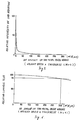
- Fig. 5 is a graph for explaining a relation between intensity of UVB emitted from the lamps and an amount of the metal oxide grains dispersed in the overcoated layer;
- Fig. 6 is a graph for explaining a relation between luminous flux of the lamps and an amount of the metal oxide grains dispersed in the overcoated layer;
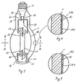
- Fig. 7 is a front view of a metal halide lamp according to a second embodiment of the present invention;
- Fig. 8 is a partial sectional view of Fig. 7; and
- Fig. 9 is a partial sectional view of a third embodiment of the present invention.
- Referring to the accompanying drawings, embodiments of the present invention will be described. However, in the drawings, the same numerals are applied to the similar elements in the drawings, and therefore the detailed descriptions thereof are not repeated.
- Fig. 1 is a front view of a metal halide lamp according to the first embodiment of the present invention.
- The metal halide lamp has an
outer envelope 11 made of hard glass. Theouter envelope 11 forms a shape, so called BT-shape, swelling around a centre thereof and forms thin portions at both ends of theouter envelope 11 as compared with a portion around the centre of theouter envelope 11. One thin portion is aneck portion 13 and the other is atop portion 15. Theneck portion 13 has abase 17 for attaching the lamp to lighting equipment (not shown) and for recieving electric power. - The
outer envelope 11 includes aninner tube 19 therein Theinner tube 19 is made of quartz glass. A pair ofelectrodes 21 and 22 are provided at both ends in theinner tube 19. A rare gas as a starting gas such as argon and a discharge gas such as may be derived from mercury, sodium halide and scandium halide are sealed in theinner tube 19. - The
inner tube 19 is supported in theouter envelope 11 by a pair of supportingwires holders wire 23 is fixed byelastic members top portion 15 and the other supportingwire 25 is connected with and supported by thelead wire 33 which is mounted to astem portion 37. The electrode 21 is connected electrically with theother lead wire 35 through a connectingwire 38. Theother electrode 22 is connected electrically with the other supportingwire 25. Both of thelead wires base 17. Accordingly, both ofelectrodes 21 and 22 are are connected electrically with thebase 17. - An overcoated
layer 39 is coated on an outsideouter glass envelope 11 shown in Fig. 2 which indicates a partial sectional view of theouter glass envelope 11 of the lamp. The overcoatedlayer 39 essentially consists of fluorocarbon polymer containing metal oxide grains (not shown) dispersed therein and has a thickness of about 100 µm. An undercoatedlayer 41 is formed between the overcoatedlayer 39 and the outer surface of theouter glass envelope 11. - The fluorocarbon polymer of this embodiment essentially consists of tetrafluoroethylene - perfluoroalkylvinylether copolymer (called PFA) (MP-103: available from MITSUI DUPONT FLUOROCHEMICAL CO., LTD in Japan), but other fluorocarbon polymers, for example tetrafluoroethylene - hexafluoropropylene copolymer (called FEP), tetrafluoroethylene - hexafluoropropylene - perfluoroalkylvinylether copolymer (called EPE) (available from MITSUI DUPONT FLUOROCHEMICAL CO., LTD in Japan) and so on, may be used. The metal oxide grains of this embodiment consist of zinc oxide (ZnO) (available from SUMITOMO SEMENTO CO., LTD in Japan) and titanium oxide (TiO₂) (available from SUMITOMO SEMENTO CO., LTD in Japan), but other metal oxide, for example tantalum oxide (Ta₂O₅), silicon oxide (SiO₂), alminium oxide (Al₂O₃) and so on, may be used. The weight of metal oxide grains is 1 % by weight of fluorocarbon polymer. An average particle size of grains of zinc oxide (ZnO) and titanium oxide (TiO₂) is about 0.02 µm, and the weight of zinc oxide (ZnO) and the weight of titanium oxide (TiO₂) are the same as each other.
- The undercoated
layer 41 is formed by coating a mixed agent, generally called a primer, of a noionic surface active agent (458-500: available from MITSUI DUPONT FLUOROCHEMICAL CO., LTD in Japan), a certain amount of silicon oxide (SiO₂) grains and alminium oxide (Al₂O₃) grains on the outer surface of theouter glass envelope 11 and drying the coated agent. It is necessary to eliminate fats and oils from the outer surface of theouter glass envelope 11, for example, by washing or baking before coating the mixed agent. - After coating the undercoated
layer 41, the overcoatedlayer 39 is formed by steps including a well known electrostatic coating method. The first step is preparing a mixed powder containing the powder of the fluorocarbon polymer, the powder of zinc oxide (ZnO) grains and the powder of titanium oxide (TiO₂) grains. The detail of each powder is described above. The next step is coating the mixed powder on the surface of the undercoatedlayer 41 in an area of the undercoatedlayer 41 by the electrostatic coating method. In this case, the undercoatedlayer 41 works as an electrode attracting charged particles of powder. Therefore, the overcoatedlayer 39 is formed only on the undercoatedlayer 41. The next step is heating the powder coated on the surface of theouter glass envelope 11 at a temperature of 310 °C to 400 °C in order that the powder of the fluorocarbon polymer melts and forms a continuous layer of the fluorocarbon polymer, i.e. the overcoatedlayer 39. As is understood from the above description, the undercoatedlayer 41 is coated not only in order to increase the adhesive strength of theovercoated layer 39 with respect to the outer surface of theouter glass envelope 11 but also in order to form theovercoated layer 39. - According to the above described method, the
overcoated layer 39 has an even density of the metal oxide grains at any position thereof because the above described method does not use liquid, and is not wet coating. Therefore the metal oxide grains do not collect or aggregate unevenly during forming of theovercoated layer 39. In other words, the above described method does not have the disadvantage that the metal oxide grains would collect at one side of the envelope during drying of the coating liquid because of the effect of gravity. Moreover theovercoated layer 39 has an even thickness at any position thereof since the above described method does not use liquid and therefore does not have the defect that coating liquid would flow and drop toward one side of the envelope during the step for drying the coating liquid. - Fig. 3 shows measured results of tensile strength of the
overcoated layer 39 of the lamps when the weight ratio of the metal oxide grains dispersed in theovercoated layer 39 is varied. In Fig. 3, a horizontal axis indicates the weight ratio of the metal oxide grains and a vertical axis indicates relative value of the tensile strength of theovercoated layer overcoated layer 39 without the metal oxide grains. As described above, an average particle size of the metal oxide grains is 0.02 µm and the thickness of theovercoated layer 39 is about 100 µm. - According to the measured results of Fig. 3, the tensile strength increased, accompanied by an incease of the weight ratio of the metal oxide grains in the range of more than 0.05% of the metal oxide grains.
- The reason why the tensile strength increased is thought to be that the metal oxide grains dispersed between overlapped fluorocarbon polymer molecules of the
overcoated layer 39 prevent slipping between fluorocarbon polymer molecules. Moreover, the following is supposed. As theovercoated layer 39 formed by the above described method has the even density of the metal oxide grains at any position thereof and there is no position that has extremely low density of the metal oxide grains, there is no position that has an extremely weak tensile strength as compared with other positions. It is thought that the tensile strength increased because of the above described reason. - Similar results were obtained in cases of other kinds of metal oxide grains and different particle sizes.
- Fig. 4 shows measured results of luminous flux of the lamps, varing the weight ratio and the average particle size of the metal oxide grains dispersed in the
overcoated layer 39. In Fig. 4, a horizontal axis indicates the weight ratio of the metal oxide grains and a vertical axis indicates relative value of the luminous flux of the lamps, and 100% means the luminous flux of the lamps in case that theovercoated layer 39 does not have the metal oxide grains. The three lines (a), (b) and (c) correspond to the average particle size of 0.02 µm, 0.1 µm and 0.2 µm respectively. - According to the measured results of Fig. 4, the luminous flux decreased, accompanied by an increase of the weight ratio of the metal oxide grains. This indicates that the metal oxide grains of the
overcoated layer 39 absorb the light. In this case, the decrease of the luminous flux was not so much within the range of 3 % of the weight ratio of the metal oxide grains, but it was too much beyond the range of 3 % of the weight ratio of the metal oxide grains. It is also understood that the decrease of the luminous flux was too much when the particle size was more than 0.1 µm even if the weight ratio of the metal oxide grains was small. When the weight ratio of the metal oxide grains is too much, theovercoated layer 39 may have the defects of opacity or non-transparency. - Similar results were obtained for other types of metal oxide grains.
- Accordingly, the preferable range of the particle size of the metal oxide grains was determined to be not more than 0.1 µm and the preferable range of the weight ratio of the metal oxide grains was determined to be from 0.05 to 3 %.
- Fig. 5 shows measured results of intensity of ultraviolet rays emitted from the lamps, varying the weight ratio (M wt%) of the metal oxide grains dispersed in the
overcoated layer 39 and the thickness (t µm) of theovercoated layer 39. The metal oxide grains of the lamps comprise titanium oxide (TiO₂) and zinc oxide (ZnO) as described above. The ultraviolet rays of wavelength 280 - 320 nm, which is called UVB, was measured. In Fig. 5, a horizontal axis indicates an amount (Mxt) of the metal oxide grains dispersed in theovercoated layer 39. The amount (Mxt) of the metal oxide grains dispersed in theovercoated layer 39 is defined as a multiple of the weight ratio (M) of the metal oxide grains and the thickness (t) of theovercoated layer 39. A vertical axis indicates relative intensity of UVB emitted from the lamps and 100 % means the intensity of UVB where theovercoated layer 39 does not contain the metal oxide grains. - As shown in Fig. 5, the intensity of UVB emitted from the lamp decreased, accompanied by an increase of the weight ratio (M) of the metal oxide grains and the thickness (t) of the
overcoated layer 39. Especially, the intensity of UVB emitted from the lamp which has, as described above, 100 µm thickness of theovercoated layer 39 containing 1 % weight of the metal oxide grains of titanium oxide (TiO₂) and zinc oxide (ZnO) decreases under a hundredth as much as the intensity of UVB emitted from the lamp having theovercoated layer 39 not containing the metal oxide grains. Further, the intensity of UVB emitted from the lamp which has 5 wt%µm (=M×t) of the amount of the metal oxide grains is a half of the intensity of UVB emitted from the lamp having theovercoated layer 39 not containing the metal oxide grains. In general, it is understood that the effect of suppressing fading is obtained by decreasing the intensity of the UVB by a half. Therefore, preferred lamps have more than 5 wt%µm (=M×t) of the amount of the metal oxide grains in order to suppress fading. Similar results were obtained with regard to the lamps which have theovercoated layer 39 containing different particle sizes of the metal oxide grains, and were also obtained in lamps which have theovercoated layer 39 containing different types of metal oxide grains such as only titanium oxide (TiO₂), only zinc oxide (ZnO) or a mixture comprising cerise oxide (CeO). - Fig. 6 shows the relation between luminous flux of the lamp and the amount (M×t) of the metal oxide grains. In Fig. 6, a horizontal axis indicates the amount (M×t) of the metal oxide grains and a vertical axis indicates relative value of the luminous flux of the lamp, and 100 % means the luminous flux of the lamp whose
overcoated layer 39 does not have the metal oxide grains, or 100 % means the luminous flux of the lamp which does not have theovercoated layer 39. Fig. 6 was obtained under the condition that the metal oxide grains consisted of the same amounts of titanium oxide (TiO₂) and zinc oxide (ZnO) which had an average particle size of about 0.02 µm and that theovercoated layer 39 had a thickness of about 100 µm. - As shown in Fig. 6, the intensity of the luminous flux emitted from the lamp decreased, accompanied by an increase of the weight ratio (M) of the metal oxide grains and the thickness (t) of the
overcoated layer 39. These results coincide with the measured results shown in Fig. 4. In this case, the decrease of the luminous flux was not so much within 300 (wt% × µm) of the amount of the metal oxide grains, but it was too much beyond 300 (wt% × µm) of the amount of the metal oxide grains. Further theovercoated layer 39 may have defects of opacity or non-transparency where the amount (M×t) of the metal oxide grains is beyond 300 (wt% × µm), the same as the results according to Fig. 4. - Similar results were obtained for other types of metal oxide grains and for different particle sizes of the metal oxide grains.
- According to the measured results regarding to Fig. 5 and Fig. 6, the preferred amount of the metal oxide grains satisfies the following relationship:

- Fig. 7 and Fig.8 show a second embodiment of the present invention. In the drawings, the same numerals are applied to the similar elements to the first embodiment, and therefore detailed description thereof is not repeated.
- The weight ratio (or density) of the metal oxide grains of the
overcoated layer 39 of the lamp of this embodiment varies according to positions of theovercoated layer 39. This is the only difference between the lamp of this embodiment and the lamp of the first embodiment. The weight ratio of the metal oxide grains of the overcoated layer 39a is 0.75 wt% at the top side area A of the lamp including thetop portion 15 of theenvelope 11, and the weight ratio of the metal oxide grains of the overcoated layer 39b is 1 wt% at the base side area B of the lamp including theneck portion 13 of theenvelope 11. A boundary between the top side area A and the area base side B is positioned at the thickest portion of theenvelope 11. The thickness of theovercoated layer 39 is 100 µm on both sides, as in the first embodiment. The other elements of this embodiment are the same as the first embodiment. - The lamp having two kinds of overcoated layers is obtained by preparing two kinds of coating mixtures having different weight ratios of the metal oxide grains and by coating each mixture on the specific area of the
envelope 11 in two steps. - It was found that the metal oxide grains dispersed in the
overcoated layer 39 disturbed radiation of heat from the lamp. Considering this fact, it is preferred that the weight ratio (or density) of the metal oxide grains at the portion of theenvelope 11 tending to have high temperature be lower than that at the portion of theenvelope 11 tending to have low temperature. Generally, these kinds of lamps, having a single base, are frequently attached to lighting equipment for use where the base is upward, and accordingly the top side area A of theenvelope 11 tends to have high temperature. Therefore, the weight ratio of the metal oxide grains at the top area A of theenvelope 11 is preferably lower than that at the base area B of theenvelope 11, so as to radiate heat effectively from the lamp. - As shown in Fig. 9, instead of varying the weight ratio of the metal oxide grains according to the area of the
envelope 11, it may be possible to vary the thickness of theovercoated layer 39 according to the top area A and the base area B, keeping a set value of the weight ratio of the metal oxide grains in both areas. In this case, thickness of the overcoated layer 39a at the top area A of theenvelope 11 is thinner than that of the overcoated layer 39b at the base area B of theenvelope 11. - The present invention may be applied not only to the metal halide lamps described above, but also to high intensity discharge lamps such as high pressure sodium lamps, high pressure mercury discharge lamps and so on. Further, the present invention may be applied to halogen lamps. In this case, a tungsten filament emits light and heats an envelope, which is usually made from quartz glass, at more than 200 °C. Therefore the present invention is also suitable for halogen lamps.
- In summary, it will be seen that the present invention overcomes or otherwise mitigates the disadvantages of the prior art and provides an improved layer for preventing glass pieces from scattering should the glass envelope of the lamp be broken.
Claims (15)
- A lamp comprising:
means (19), (21), (22) for emitting light and heat;
an envelope (11) surrounding said means (19), (21), (22) capable of being heated to a temperature greater than 200 °C by said means (19), (21), (22); and
a first layer (39) coated on the ouside of said envelope (11), said layer (39) comprising a fluorocarbon polymer; said lamp being characterized in that said fluorocarbon polymer contains metal oxide grains dispersed therein. - A lamp according to claim 1, wherein said metal oxide grains comprise at least one of the following: TiO₂ , ZnO₂ , SiO₂ , Ta₂ O₅ , Al₂ O₃ and CeO.
- A lamp according to claim 1 or 2, wherein the average particle size of said metal oxide grains is not more than 0. 1 µm
- A lamp according to any preceding claim, wherein the weight ratio of said metal oxide grains to fluorocarbon polymer is 0.05 % to 3%
- A lamp according to any preceding claim, wherein said means emits ultraviolet rays and said metal oxide grains suppress said ultraviolet rays.
- A lamp according to claim 5, wherein said metal oxide grains comprise at least one of the following: TiO₂, ZnO₂ and CeO.
- A lamp according to claim 5 or 6, wherein the weight ratio (M wt%) of said metal oxide grains and the thickness (t µm) of said overcoated layer (39) satisfy the following relation:

- A lamp according to any preceding claim, further comprising a second layer (41) formed between said envelope (11) and said first layer (39) for increasing the adhesive strength of said first layer (39) to said envelope (11).
- A lamp according to any preceding claim, being a high intensity gas discharge lamp wherein said means (19), (21), (22) is a light emitting tube having an inner tube (19), a discharge gas contained in or capable of being generated in said inner tube (19) and a pair of electrodes (21), (22) disposed in said inner tube (19), so as to emit light and heat generated by discharge of said discharge gas.
- A lamp according to any preceding claim, wherein said first layer has a plurality of portions of varying thickness and/or varying weight ratio portions of said metal oxide grains, such as one or more thick portions optionally (39b) of high weight ratio and one or more thin portions optionally of low weight ratio of said metal oxide grains
- A lamp according to claim 10, further comprising a base (17), attached to a position of said envelope (11) corresponding to said thick portion (39b) of said first layer (39), so as to obtain electric power and to supply said electric power to said means (19), (21), (22).
- A method of forming a layer comprising a fluorocarbon polymer containing metal oxide grains onto an envelope (11) of a lamp, comprising:
preparing a mixed powder containing said metal oxide grains and powder of said fluorocarbon polymer;
coating said mixed powder to said envelope (11) by electrostatic coating means; and
melting said powder of said fluorocarbon polymer by heating so as to form a continuous layer comprising said fluorocarbon polymer containing metal oxide grains. - A method of forming a layer according to claim 12, further comprising forming a primer layer (41), which is electroconductive, on said envelope (11), before coating said mixed powder.
- A method of forming a layer according to claim 12 or 13, wherein said primer layer (41) contains metal oxide grains.
- Use of a method of forming a layer as claimed in any one of claims 12 to 14 in the production of a lamp as claimed in any one of claims 1 to 11.
Applications Claiming Priority (4)
| Application Number | Priority Date | Filing Date | Title |
|---|---|---|---|
| JP96311/90 | 1990-04-13 | ||
| JP2096311A JPH03295147A (en) | 1990-04-13 | 1990-04-13 | Tubular bulb |
| JP297176/90 | 1990-11-05 | ||
| JP29717690 | 1990-11-05 |
Publications (2)
| Publication Number | Publication Date |
|---|---|
| EP0452133A1 EP0452133A1 (en) | 1991-10-16 |
| EP0452133B1 true EP0452133B1 (en) | 1994-10-12 |
Family
ID=26437535
Family Applications (1)
| Application Number | Title | Priority Date | Filing Date |
|---|---|---|---|
| EP91303221A Expired - Lifetime EP0452133B1 (en) | 1990-04-13 | 1991-04-11 | Polymer coated lamps and their production |
Country Status (3)
| Country | Link |
|---|---|
| EP (1) | EP0452133B1 (en) |
| KR (1) | KR940009201B1 (en) |
| DE (1) | DE69104530T2 (en) |
Families Citing this family (3)
| Publication number | Priority date | Publication date | Assignee | Title |
|---|---|---|---|---|
| DE10213294B4 (en) * | 2002-03-25 | 2015-05-13 | Osram Gmbh | Use of a UV-resistant polymer in optoelectronics and outdoor applications, UV-resistant polymer and optical component |
| DE102005021089A1 (en) * | 2005-05-06 | 2006-12-07 | Rehau Ag + Co. | Coating material, useful for light source, preferably fluorescent tubes, comprises a polymer material composition containing a specific amount of partially crystalline fluoropolymer and a zincoxide component |
| KR20110037743A (en) * | 2009-10-07 | 2011-04-13 | 옥도영 | Api uv lamp |
Family Cites Families (4)
| Publication number | Priority date | Publication date | Assignee | Title |
|---|---|---|---|---|
| JPS5649956B2 (en) * | 1973-08-17 | 1981-11-26 | ||
| CA1243723A (en) * | 1984-09-17 | 1988-10-25 | Peter R. Gagnon | Electric lamp including a containment coating as part thereof |
| JPS61110959A (en) * | 1984-11-05 | 1986-05-29 | Toshiba Corp | Fluorescent lamp |
| US4866328A (en) * | 1988-04-15 | 1989-09-12 | North American Philips Corp. | Electric lamp with reduced internal photoelectron production |
-
1991
- 1991-04-11 DE DE69104530T patent/DE69104530T2/en not_active Expired - Fee Related
- 1991-04-11 EP EP91303221A patent/EP0452133B1/en not_active Expired - Lifetime
- 1991-04-13 KR KR1019910006012A patent/KR940009201B1/en not_active Expired - Fee Related
Also Published As
| Publication number | Publication date |
|---|---|
| DE69104530T2 (en) | 1995-02-23 |
| KR940009201B1 (en) | 1994-10-01 |
| KR910019105A (en) | 1991-11-30 |
| EP0452133A1 (en) | 1991-10-16 |
| DE69104530D1 (en) | 1994-11-17 |
Similar Documents
| Publication | Publication Date | Title |
|---|---|---|
| US5258689A (en) | Fluorescent lamps having reduced interference colors | |
| US5243251A (en) | Lamp having a glass envelope with fluorocarbon polymer layer | |
| US5220237A (en) | Metal halide lamp apparatus | |
| US4418300A (en) | Metal vapor discharge lamp with heat insulator and starting aid | |
| US5917291A (en) | Electrodeless fluorescent lamp having an improved phosphor distribution arrangement and a method of making the same | |
| US5539277A (en) | Fluorescent lamp having high resistance conductive coating adjacent the electrodes | |
| US20050068775A1 (en) | Compact self-ballasted fluorescent lamp and manufacturing method for arc tube | |
| CN1069994C (en) | Metal halide gas discharge lamp for projection purposes | |
| JP4461019B2 (en) | Electric lamp / reflector unit | |
| EP0452133A1 (en) | Polymer coated lamps and their production | |
| KR101029501B1 (en) | Mercury free high pressure gas discharge lamp | |
| JPH1050254A (en) | Arc discharge light source | |
| CN1527355A (en) | Halogen lamps with IR-reflecting coating and with reflector and IR-reflecting coating | |
| JP2003051284A (en) | Fluorescent lamps and lighting equipment | |
| EP0101519B1 (en) | Metal vapor discharge lamp | |
| US7453205B2 (en) | High-pressure gas discharge lamp | |
| JPH11162406A (en) | High pressure discharge lamp, floodlight device and projector device | |
| WO2005032215A1 (en) | Tube and ball | |
| US20080054776A1 (en) | Light source device | |
| JP2004342446A (en) | Light source device | |
| JPS61232553A (en) | Reflection type metal halide lamp | |
| EP0604207B1 (en) | A metal halide arc discharge lamp | |
| JPH10214602A (en) | Rapid start type fluorescent lamp and lighting equipment | |
| JPH08255591A (en) | Metal halide lamp | |
| JPH0427667B2 (en) |
Legal Events
| Date | Code | Title | Description |
|---|---|---|---|
| PUAI | Public reference made under article 153(3) epc to a published international application that has entered the european phase |
Free format text: ORIGINAL CODE: 0009012 |
|
| 17P | Request for examination filed |
Effective date: 19910426 |
|
| AK | Designated contracting states |
Kind code of ref document: A1 Designated state(s): DE GB |
|
| 17Q | First examination report despatched |
Effective date: 19931207 |
|
| GRAA | (expected) grant |
Free format text: ORIGINAL CODE: 0009210 |
|
| AK | Designated contracting states |
Kind code of ref document: B1 Designated state(s): DE GB |
|
| REF | Corresponds to: |
Ref document number: 69104530 Country of ref document: DE Date of ref document: 19941117 |
|
| PLBE | No opposition filed within time limit |
Free format text: ORIGINAL CODE: 0009261 |
|
| STAA | Information on the status of an ep patent application or granted ep patent |
Free format text: STATUS: NO OPPOSITION FILED WITHIN TIME LIMIT |
|
| 26N | No opposition filed | ||
| REG | Reference to a national code |
Ref country code: GB Ref legal event code: 746 Effective date: 20010524 |
|
| REG | Reference to a national code |
Ref country code: GB Ref legal event code: IF02 |
|
| PGFP | Annual fee paid to national office [announced via postgrant information from national office to epo] |
Ref country code: DE Payment date: 20070405 Year of fee payment: 17 |
|
| PGFP | Annual fee paid to national office [announced via postgrant information from national office to epo] |
Ref country code: GB Payment date: 20070411 Year of fee payment: 17 |
|
| GBPC | Gb: european patent ceased through non-payment of renewal fee |
Effective date: 20080411 |
|
| PG25 | Lapsed in a contracting state [announced via postgrant information from national office to epo] |
Ref country code: DE Free format text: LAPSE BECAUSE OF NON-PAYMENT OF DUE FEES Effective date: 20081101 |
|
| PG25 | Lapsed in a contracting state [announced via postgrant information from national office to epo] |
Ref country code: GB Free format text: LAPSE BECAUSE OF NON-PAYMENT OF DUE FEES Effective date: 20080411 |