EP0452087B1 - Mineral insulated cable manufacture - Google Patents
Mineral insulated cable manufacture Download PDFInfo
- Publication number
- EP0452087B1 EP0452087B1 EP91303109A EP91303109A EP0452087B1 EP 0452087 B1 EP0452087 B1 EP 0452087B1 EP 91303109 A EP91303109 A EP 91303109A EP 91303109 A EP91303109 A EP 91303109A EP 0452087 B1 EP0452087 B1 EP 0452087B1
- Authority
- EP
- European Patent Office
- Prior art keywords
- preformed body
- tube
- copper
- powder
- delivery tube
- Prior art date
- Legal status (The legal status is an assumption and is not a legal conclusion. Google has not performed a legal analysis and makes no representation as to the accuracy of the status listed.)
- Expired - Lifetime
Links
- 238000004519 manufacturing process Methods 0.000 title claims abstract description 14
- 229910052500 inorganic mineral Inorganic materials 0.000 title claims description 31
- 239000011707 mineral Substances 0.000 title claims description 31
- 239000000843 powder Substances 0.000 claims abstract description 98
- XKRFYHLGVUSROY-UHFFFAOYSA-N Argon Chemical compound [Ar] XKRFYHLGVUSROY-UHFFFAOYSA-N 0.000 claims abstract description 68
- RYGMFSIKBFXOCR-UHFFFAOYSA-N Copper Chemical compound [Cu] RYGMFSIKBFXOCR-UHFFFAOYSA-N 0.000 claims abstract description 64
- 229910052802 copper Inorganic materials 0.000 claims abstract description 64
- 239000010949 copper Substances 0.000 claims abstract description 64
- 238000003466 welding Methods 0.000 claims abstract description 37
- 229910052786 argon Inorganic materials 0.000 claims abstract description 34
- 239000011261 inert gas Substances 0.000 claims abstract description 27
- 239000000919 ceramic Substances 0.000 claims abstract description 10
- 239000004020 conductor Substances 0.000 claims description 21
- 238000000034 method Methods 0.000 claims description 14
- 239000000463 material Substances 0.000 claims description 12
- 238000011144 upstream manufacturing Methods 0.000 claims description 10
- 238000009751 slip forming Methods 0.000 claims description 7
- 229910000881 Cu alloy Inorganic materials 0.000 claims description 6
- 229910052581 Si3N4 Inorganic materials 0.000 claims description 3
- 230000002093 peripheral effect Effects 0.000 claims description 3
- HQVNEWCFYHHQES-UHFFFAOYSA-N silicon nitride Chemical compound N12[Si]34N5[Si]62N3[Si]51N64 HQVNEWCFYHHQES-UHFFFAOYSA-N 0.000 claims description 3
- 239000003779 heat-resistant material Substances 0.000 abstract 1
- 238000001914 filtration Methods 0.000 description 3
- 239000000853 adhesive Substances 0.000 description 2
- 230000001070 adhesive effect Effects 0.000 description 2
- QVGXLLKOCUKJST-UHFFFAOYSA-N atomic oxygen Chemical compound [O] QVGXLLKOCUKJST-UHFFFAOYSA-N 0.000 description 2
- 239000001301 oxygen Substances 0.000 description 2
- 229910052760 oxygen Inorganic materials 0.000 description 2
- 239000011324 bead Substances 0.000 description 1
- 238000005056 compaction Methods 0.000 description 1
- 230000007547 defect Effects 0.000 description 1
- 230000002708 enhancing effect Effects 0.000 description 1
- 239000012530 fluid Substances 0.000 description 1
- 239000007789 gas Substances 0.000 description 1
- 239000000395 magnesium oxide Substances 0.000 description 1
- CPLXHLVBOLITMK-UHFFFAOYSA-N magnesium oxide Inorganic materials [Mg]=O CPLXHLVBOLITMK-UHFFFAOYSA-N 0.000 description 1
- AXZKOIWUVFPNLO-UHFFFAOYSA-N magnesium;oxygen(2-) Chemical compound [O-2].[Mg+2] AXZKOIWUVFPNLO-UHFFFAOYSA-N 0.000 description 1
- 229910052751 metal Inorganic materials 0.000 description 1
- 239000002184 metal Substances 0.000 description 1
- 229910001092 metal group alloy Inorganic materials 0.000 description 1
- 238000004021 metal welding Methods 0.000 description 1
- 238000012544 monitoring process Methods 0.000 description 1
- 125000006850 spacer group Chemical group 0.000 description 1
- 230000006641 stabilisation Effects 0.000 description 1
- 239000010935 stainless steel Substances 0.000 description 1
- 229910001220 stainless steel Inorganic materials 0.000 description 1
Images
Classifications
-
- B—PERFORMING OPERATIONS; TRANSPORTING
- B23—MACHINE TOOLS; METAL-WORKING NOT OTHERWISE PROVIDED FOR
- B23K—SOLDERING OR UNSOLDERING; WELDING; CLADDING OR PLATING BY SOLDERING OR WELDING; CUTTING BY APPLYING HEAT LOCALLY, e.g. FLAME CUTTING; WORKING BY LASER BEAM
- B23K9/00—Arc welding or cutting
- B23K9/02—Seam welding; Backing means; Inserts
- B23K9/025—Seam welding; Backing means; Inserts for rectilinear seams
- B23K9/0253—Seam welding; Backing means; Inserts for rectilinear seams for the longitudinal seam of tubes
-
- B—PERFORMING OPERATIONS; TRANSPORTING
- B23—MACHINE TOOLS; METAL-WORKING NOT OTHERWISE PROVIDED FOR
- B23K—SOLDERING OR UNSOLDERING; WELDING; CLADDING OR PLATING BY SOLDERING OR WELDING; CUTTING BY APPLYING HEAT LOCALLY, e.g. FLAME CUTTING; WORKING BY LASER BEAM
- B23K9/00—Arc welding or cutting
- B23K9/02—Seam welding; Backing means; Inserts
- B23K9/035—Seam welding; Backing means; Inserts with backing means disposed under the seam
- B23K9/0356—Seam welding; Backing means; Inserts with backing means disposed under the seam the backing means being a tape or strip
-
- H—ELECTRICITY
- H01—ELECTRIC ELEMENTS
- H01B—CABLES; CONDUCTORS; INSULATORS; SELECTION OF MATERIALS FOR THEIR CONDUCTIVE, INSULATING OR DIELECTRIC PROPERTIES
- H01B13/00—Apparatus or processes specially adapted for manufacturing conductors or cables
- H01B13/004—Apparatus or processes specially adapted for manufacturing conductors or cables for manufacturing rigid-tube cables
Definitions
- This invention relates to a method of, and apparatus for, manufacturing mineral insulated electric cables, that is to say cables of the kind comprising at least one elongate conductor insulated from a surrounding sheath of metal or metal alloy, and where there is more than one elongate conductor from the other conductor or conductors, by compacted mineral insulating powder, usually but not necessarily magnesium oxide.
- the welding step may be conducted with an atmosphere of argon or other inert gas on the radially inward side of the copper tube so formed.
- a preformed body of a fluid-permeable ceramic or sintered material capable of withstanding the temperature to which it will be subjected during the welding operation and the argon or other inert gas fed into the fluid-permeable ceramic or sintered material of the preformed body from at least one pipe is caused to flow radially outwardly through the preformed body to provide the environment of argon or other inert gas between the preformed body and the copper tube in the vicinity of the welding station.
- Fluid permeable bodies have been employed for the introduction of argon into the weld area during butt welding of metal pipes, for example as described in DE-A-1934107.
- the peripheral side surfaces of the preformed body are sealed to render them substantially fluid-impermeable.
- a substantially centrally disposed major portion of the radially inner surface of the preformed body is bounded by a peripherally continuous part of said radially inner surface and is radially spaced from the powder delivery tube to form a closed chamber into which argon or other inert gas from said pipe or pipes is fed and from which argon or other inert gas flows radially outwardly through the fluid-permeable material of the preformed body.
- the preformed body has in its radially outer surface a groove which extends lengthwise with respect to the powder delivery tube and which is disposed radially inwardly of the continuous weld. Since the radial thickness of the preformed body is at a minimum in the vicinity of this groove, argon or other inert gas will tend to flow towards and radially outwardly of the groove and hence towards the immediate vicinity of the continuous weld.
- the groove preferably is closed at its upstream end so that argon or other inert gas will also tend to flow along the groove and between the preformed body and the copper tube in the same direction of travel as the copper tube.
- the preformed body may have a radially outer surface which forms part of the outer surface of an imaginary cylinder of a similar shape to but smaller than that of the copper tube being formed; usually the copper tube will be of substantially circular cross-section.
- the or each pipe by means of which argon or other inert gas is fed into the preformed body of fluid-permeable ceramic or sintered material may be disposed lengthwise in the powder delivery tube and may protrude through the wall of the powder delivery tube into the pressure-equalising chamber formed between the preformed body and the powder delivery tube but, preferably, the preformed body is of elongate shape shape and argon or other gas is fed into the pressure-equalising chamber formed between the preformed body and the powder delivery tube through each of two pipes which are disposed lengthwise between the powder delivery tube and the advancing copper tube and which pass through opposite ends of the preformed body and open into the pressure-equalising chamber.
- argon or other inert gas preferably is caused to flow back between the powder delivery tube and the copper tube at a position circumferentially remote from the welding station.
- the preformed body is bonded to the outer surface of the powder delivery tube by a heat-resistant adhesive.
- the preformed body may be manufactured of any ceramic or sintered material which is capable of withstanding the temperatures to which the body will be subjected during the welding operation, which can be machined or otherwise worked to form a body of the required shape and size to the required tolerances and which can be rendered fluid-permeable; preferred materials include reaction bonded silicon nitride and stainless steel.
- the invention also includes apparatus for manufacturing mineral insulated electric cable by the improved method hereinbefore described.
- the invention further includes a mineral insulated electric cable manufactured by the improved method hereinbefore described.
- the improved method and apparatus of the present invention are especially, but not exclusively, applicable to the method of and apparatus for manufacturing mineral insulated electric cable as described and claimed in the specification of our co-pending Patent Application No: 9004185.6 (Serial No: 2230894).
- the preferred apparatus for use in the preferred method of manufacturing mineral insulated electric cable comprises a powder delivery tube 1 which over a major part of its length is disposed substantially horizontally and which, over a minor part 2 of its length at its upstream end, is smoothly curved in an upward direction.
- the minor end part 2 of the delivery tube 1 constitutes one branch of a bifurcated tubular fitting 3, the second branch 4 of which is in axial alignment with the major part of the length of the delivery tube 1.
- a fluid-tight main chamber 7 for mineral insulating powder Positioned above and upstream of the minor end part 2 of the delivery tube 1 is a fluid-tight main chamber 7 for mineral insulating powder, which chamber is detachably connected to the minor end part of the delivery tube by a smoothly curved pipe 6.
- a fluid-tight supplementary powder chamber 11 for automatically re-charging the main chamber 7 is disposed above and connected via an automatically-operable valve 12 to the main chamber.
- the main powder chamber 7 and supplementary powder chamber 11 are also interconnected by a pipe 9 in which is fitted an automatically-operable valve 10.
- the supplementary powder chamber 11 has at its upper end an outlet pipe 16 open to the atmosphere in which is an automatically operable valve 13.
- a hopper 15 mounted above the supplementary powder chamber 11 and fed with mineral insulating powder from a bulk source (not shown) is connected to the supplementary powder chamber via an automatically-operable valve 14.
- the main powder chamber 7 incorporates a level sensor 18 for detecting a predetermined minimum level of powder in the chamber and the supplementary powder chamber 11 has a level detector 19 for detecting a predetermined maximum level of powder in the supplementary chamber.
- Clean dry air from a source (not shown) is continuously injected into the main powder chamber 7 through a pipe 20 via a pressure controller 21, an accumulator 22 and a valve 23, the pressure of the clean dry air being recorded by a gauge 24.
- the pipe 20 extends around the chamber and has in its wall a multiplicity of mutually spaced apertures through which dry clean air under the required predetermined pressure is expelled in a plurality of directions into the chamber.
- a rotatably driven screw (not shown) may be so disposed in the main powder chamber 7 that, when the screw is rotatably driven about its axis, mineral insulating powder is encouraged to flow towards the outlet of the chamber and down the pipe 6.
- a welding station 25 at which the edges of an advancing strip T of copper or copper alloy, which is travelling in the direction of its length and is being transversely folded into tubular form around the powder delivery tube so that it surrounds and is radially spaced from the delivery tube, are continuously welded together to form a copper sheath tube into which mineral insulating powder is to be fed and partially compacted around advancing conductor rods C at a required fill density.
- a separately formed fitting 26 which incorporates or constitutes filtered outlet ports 27 through which air is expelled from the delivery tube, at least one spacer member for locating the conductor rod C positively with respect to the advancing copper tube T, a passage or passages 29 for flow of powder from the delivery tube into the copper tube and filtering means 28 disposed between the fitting and the copper tube downstream of the filtered outlet ports.
- the powder delivery tube 1 has, extending from immediately upstream of the fitting 26 to a position downstream of the bifurcated fitting 3, four circumferentially spaced radially outwardly extending longitudinally continuous ribs 53 which bear against and space the advancing copper tube T from the delivery tube and which define four independent longitudinally extending passages.
- the downstream ends of two of the passages are closed by deflectors 58 and, upstream of the deflectors, are interconnected.
- the upstream ends of the other two passages may be open to the atmosphere via a filter bag (not shown) or may be connected to a re-claim or re-cycling plant.
- the apparatus may include at least one device (not shown) for vibrating the powder filled tube to assist in partial compaction of the powder in the tube and around the conductor rods.
- a preformed elongate body of fluid-permeable reaction bonded silicon nitride is bonded to the outer surface of the powder delivery tube 1 by a heat-resistant adhesive.
- the peripheral side surfaces of the preformed body 61 are sealed to render them fluid-impermeable and a centrally disposed major portion of the radially inner surface of the preformed body is bounded by a peripherally continuous part 62 of said radially inner surface and is radially spaced from the powder delivery tube 1 to form a closed chamber 63.
- the preformed body 61 has a groove 64 which extends lengthwise with respect to the powder delivery tube 1 and which is disposed radially inwardly of the continuous weld of the transversely folded copper strip T, the groove being closed at its upstream end.
- a pipe 65 is disposed lengthwise in the passage 57 between the powder delivery tube 1 and the advancing copper strip T and opens into the chamber 63;
- a pipe 66 extends alongside the preformed body 61 between the powder delivery tube and the advancing copper strip T in passage 57 and is folded back upon itself so that it opens into the chamber 63 at the downstream end of the preformed body.
- valve 10 opens to balance the pressures in the main chamber 7 and supplementary chamber 11 and, after a short time delay, valve 12 opens to allow a charge of powder to fall from the supplementary chamber into the main chamber. After a suitable time delay, valve 12 closes, valve 10 closes and then valve 13 opens to relieve the pressure in the supplementary chamber 11. After a further short time delay, valve 14 opens to allow powder from the hopper 15 to flow into the supplementary chamber 11.
- Mineral insulating powder under the pressure of the dry clean air is injected from the powder delivery tube 1 through the bore of the fitting 26 into the advancing copper tube T so that mineral insulating powder fills the space around the conductor rods C and is partially compacted under the pressure of the dry clean air.
- Dry clean air is expelled through the filter outlet ports 27, flows back between the powder delivery tube 1 and the advancing copper tube T and is deflected by the deflectors 58 to flow along two of the passages, and conveys heat emitted by the advancing copper tube.
- Filtering means 28 prevents mineral insulating powder from the copper tube T from flowing back between the copper tube and the fitting.
- the dry clean air may be expelled to the atmosphere via a filter bag (not shown) to catch any stray powder expelled with the air where it may be fed to a re-claim or re-cycling plant.
- argon is fed through the pipes 65 and 66 into the chamber 63 from where it flows radially outwardly through the preformed body 61 to provide an environment of argon between the preformed body and the copper tube T in the vicinity of the welding station.
- the chamber 63 underlies a centrally disposed major portion of the radially inner surface of the preformed body 61, argon flowing through the radially outer surface of the preformed body is at a substantially constant pressure throughout substantially the whole of the surface.
- the groove 64 in the radially outer surface of the preformed body 61 encourages argon flowing radially outwardly of the preformed body in a direction towards the continuous weld being effected in the copper tube T.
- the copper tube T may pass through a weld monitoring station 70 at which any defects in the continuously formed weld of the copper tube T are continuously identified and located by the method and apparatus as described in the specification of our co-pending British Patent Application No: 9007644.9 (Serial No: 2232250).
- the filled tube Downstream of the fitting 26, the filled tube passes through a die or dies and/or rollers to reduce the filled tube the required cross-sectional size.
- the improved method of continuously welding together the edges of the advancing, transversely folded copper strip of the present invention provides several important advantages:
Landscapes
- Engineering & Computer Science (AREA)
- Physics & Mathematics (AREA)
- Plasma & Fusion (AREA)
- Mechanical Engineering (AREA)
- Manufacturing & Machinery (AREA)
- Superconductors And Manufacturing Methods Therefor (AREA)
- Inorganic Insulating Materials (AREA)
- Insulated Conductors (AREA)
- Extrusion Moulding Of Plastics Or The Like (AREA)
Abstract
Description
- This invention relates to a method of, and apparatus for, manufacturing mineral insulated electric cables, that is to say cables of the kind comprising at least one elongate conductor insulated from a surrounding sheath of metal or metal alloy, and where there is more than one elongate conductor from the other conductor or conductors, by compacted mineral insulating powder, usually but not necessarily magnesium oxide.
- In one method of manufacturing mineral insulated electric cable currently employed and described for example in DE-A-2,418,130, GB-A-2,041,260 and GB-A-2,106,307, mineral insulating powder and a conductor rod or conductor rods are simultaneously introduced into a powder delivery tube, a copper tube is continuously formed from an advancing strip of copper or copper alloy which is transversely folded into tubular form around the powder delivery tube and whose edges are continuously welded together, mineral insulating powder and the conductor rod or rods emerging from the powder delivery tube downstream of the station at which said welding is effected pass into the copper tube so formed, the powder is densely packed in the tube and around the conductor rod or rods, and the filled tube is then caused to travel through a die or dies or other means to reduce it to the required cross-sectional size. For convenience, this known method of manufacturing mineral insulated electric cable will hereinafter be referred to as "the method of manufacturing mineral insulated electric cable as hereinbefore defined".
- As described in GB-A-2,041,260 and GB-A-2,106,307, the welding step may be conducted with an atmosphere of argon or other inert gas on the radially inward side of the copper tube so formed.
- It is an object of the present invention to provide, in the method of manufacturing mineral insulated electric cable as hereinbefore defined, an improved method of continuously welding together the edges of the advancing strip of copper or copper alloy which has been transversely folded into a tubular form.
- In the improved method according to the invention, there is disposed on the outer surface of the powder delivery tube and radially inwardly of the advancing copper strip in the vicinity of the station at which the edges of the transversely folded strip are welded together, a preformed body of a fluid-permeable ceramic or sintered material capable of withstanding the temperature to which it will be subjected during the welding operation, and the argon or other inert gas fed into the fluid-permeable ceramic or sintered material of the preformed body from at least one pipe is caused to flow radially outwardly through the preformed body to provide the environment of argon or other inert gas between the preformed body and the copper tube in the vicinity of the welding station.
- Fluid permeable bodies have been employed for the introduction of argon into the weld area during butt welding of metal pipes, for example as described in DE-A-1934107.
- Preferably, with a view to ensuring that argon or other inert gas flows through and is evenly distributed over substantially the whole of the radially outer surface of the preformed body, the peripheral side surfaces of the preformed body are sealed to render them substantially fluid-impermeable. Preferably, also, with a view to ensuring that argon or other inert gas flowing through the radially outer surface of the preformed body is at a substantially constant pressure throughout substantially the whole area of said surface, a substantially centrally disposed major portion of the radially inner surface of the preformed body is bounded by a peripherally continuous part of said radially inner surface and is radially spaced from the powder delivery tube to form a closed chamber into which argon or other inert gas from said pipe or pipes is fed and from which argon or other inert gas flows radially outwardly through the fluid-permeable material of the preformed body.
- With a view to encouraging argon or other inert gas to flow radially outwardly of the preformed body in a direction towards the continuous weld being effected, preferably the preformed body has in its radially outer surface a groove which extends lengthwise with respect to the powder delivery tube and which is disposed radially inwardly of the continuous weld. Since the radial thickness of the preformed body is at a minimum in the vicinity of this groove, argon or other inert gas will tend to flow towards and radially outwardly of the groove and hence towards the immediate vicinity of the continuous weld. The groove preferably is closed at its upstream end so that argon or other inert gas will also tend to flow along the groove and between the preformed body and the copper tube in the same direction of travel as the copper tube.
- The preformed body may have a radially outer surface which forms part of the outer surface of an imaginary cylinder of a similar shape to but smaller than that of the copper tube being formed; usually the copper tube will be of substantially circular cross-section.
- The or each pipe by means of which argon or other inert gas is fed into the preformed body of fluid-permeable ceramic or sintered material may be disposed lengthwise in the powder delivery tube and may protrude through the wall of the powder delivery tube into the pressure-equalising chamber formed between the preformed body and the powder delivery tube but, preferably, the preformed body is of elongate shape shape and argon or other gas is fed into the pressure-equalising chamber formed between the preformed body and the powder delivery tube through each of two pipes which are disposed lengthwise between the powder delivery tube and the advancing copper tube and which pass through opposite ends of the preformed body and open into the pressure-equalising chamber.
- On leaving the vicinity of the welding station, argon or other inert gas preferably is caused to flow back between the powder delivery tube and the copper tube at a position circumferentially remote from the welding station.
- Preferably, the preformed body is bonded to the outer surface of the powder delivery tube by a heat-resistant adhesive.
- The preformed body may be manufactured of any ceramic or sintered material which is capable of withstanding the temperatures to which the body will be subjected during the welding operation, which can be machined or otherwise worked to form a body of the required shape and size to the required tolerances and which can be rendered fluid-permeable; preferred materials include reaction bonded silicon nitride and stainless steel.
- The invention also includes apparatus for manufacturing mineral insulated electric cable by the improved method hereinbefore described.
- The invention further includes a mineral insulated electric cable manufactured by the improved method hereinbefore described.
- The improved method and apparatus of the present invention are especially, but not exclusively, applicable to the method of and apparatus for manufacturing mineral insulated electric cable as described and claimed in the specification of our co-pending Patent Application No: 9004185.6 (Serial No: 2230894).
- The invention is further illustrated by a description, by way of example, of the preferred method of continuously manufacturing mineral insulated electric cable in which a copper sheath tube is continuously formed by transversely folding an advancing strip of copper or copper alloy into tubular form and welding the edges of the advancing strip together, with reference to the accompanying drawings, in which:-
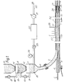
- Figure 1 is a diagrammatic side view of the preferred apparatus for use in the preferred method;
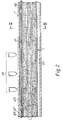
- Figure 2 is a diagrammatic sectional side view of a part of the powder delivery tube of the preferred apparatus in the vicinity of the welding station, drawn on an enlarged scale, and
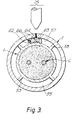
- Figure 3 is a transverse cross-sectional view of the powder delivery tube taken on the line III-III- in Figure 2.
- Referring to the drawings, the preferred apparatus for use in the preferred method of manufacturing mineral insulated electric cable comprises a powder delivery tube 1 which over a major part of its length is disposed substantially horizontally and which, over a
minor part 2 of its length at its upstream end, is smoothly curved in an upward direction. Theminor end part 2 of the delivery tube 1 constitutes one branch of a bifurcatedtubular fitting 3, the second branch 4 of which is in axial alignment with the major part of the length of the delivery tube 1. Positioned above and upstream of theminor end part 2 of the delivery tube 1 is a fluid-tight main chamber 7 for mineral insulating powder, which chamber is detachably connected to the minor end part of the delivery tube by a smoothly curved pipe 6. A fluid-tightsupplementary powder chamber 11 for automatically re-charging the main chamber 7 is disposed above and connected via an automatically-operable valve 12 to the main chamber. The main powder chamber 7 andsupplementary powder chamber 11 are also interconnected by apipe 9 in which is fitted an automatically-operable valve 10. Thesupplementary powder chamber 11 has at its upper end anoutlet pipe 16 open to the atmosphere in which is an automaticallyoperable valve 13. A hopper 15 mounted above thesupplementary powder chamber 11 and fed with mineral insulating powder from a bulk source (not shown) is connected to the supplementary powder chamber via an automatically-operable valve 14. The main powder chamber 7 incorporates alevel sensor 18 for detecting a predetermined minimum level of powder in the chamber and thesupplementary powder chamber 11 has alevel detector 19 for detecting a predetermined maximum level of powder in the supplementary chamber. Clean dry air from a source (not shown) is continuously injected into the main powder chamber 7 through apipe 20 via apressure controller 21, anaccumulator 22 and avalve 23, the pressure of the clean dry air being recorded by agauge 24. Within the main powder chamber 7, thepipe 20 extends around the chamber and has in its wall a multiplicity of mutually spaced apertures through which dry clean air under the required predetermined pressure is expelled in a plurality of directions into the chamber. A rotatably driven screw (not shown) may be so disposed in the main powder chamber 7 that, when the screw is rotatably driven about its axis, mineral insulating powder is encouraged to flow towards the outlet of the chamber and down the pipe 6. - Intermediate of the ends of the powder delivery tube 1 is a
welding station 25 at which the edges of an advancing strip T of copper or copper alloy, which is travelling in the direction of its length and is being transversely folded into tubular form around the powder delivery tube so that it surrounds and is radially spaced from the delivery tube, are continuously welded together to form a copper sheath tube into which mineral insulating powder is to be fed and partially compacted around advancing conductor rods C at a required fill density. - Detachably connected to the downstream end of the powder delivery tube 1 is a separately formed fitting 26 which incorporates or constitutes filtered
outlet ports 27 through which air is expelled from the delivery tube, at least one spacer member for locating the conductor rod C positively with respect to the advancing copper tube T, a passage orpassages 29 for flow of powder from the delivery tube into the copper tube and filtering means 28 disposed between the fitting and the copper tube downstream of the filtered outlet ports. - The powder delivery tube 1 has, extending from immediately upstream of the
fitting 26 to a position downstream of the bifurcatedfitting 3, four circumferentially spaced radially outwardly extending longitudinallycontinuous ribs 53 which bear against and space the advancing copper tube T from the delivery tube and which define four independent longitudinally extending passages. The downstream ends of two of the passages are closed bydeflectors 58 and, upstream of the deflectors, are interconnected. The upstream ends of the other two passages may be open to the atmosphere via a filter bag (not shown) or may be connected to a re-claim or re-cycling plant. - Downstream of the separately formed fitting 26 and upstream of rolls or a die or dies (not shown) for reducing the cross-sectional size of the powder filled copper tube T, the apparatus may include at least one device (not shown) for vibrating the powder filled tube to assist in partial compaction of the powder in the tube and around the conductor rods.
- In the vicinity of the
welding station 25 at which the edges of the transversely folded copper strip T are welded together, a preformed elongate body of fluid-permeable reaction bonded silicon nitride is bonded to the outer surface of the powder delivery tube 1 by a heat-resistant adhesive. The peripheral side surfaces of thepreformed body 61 are sealed to render them fluid-impermeable and a centrally disposed major portion of the radially inner surface of the preformed body is bounded by a peripherallycontinuous part 62 of said radially inner surface and is radially spaced from the powder delivery tube 1 to form a closedchamber 63. In its radially outer surface, thepreformed body 61 has a groove 64 which extends lengthwise with respect to the powder delivery tube 1 and which is disposed radially inwardly of the continuous weld of the transversely folded copper strip T, the groove being closed at its upstream end. At the upstream end of thepreformed body 61, apipe 65 is disposed lengthwise in thepassage 57 between the powder delivery tube 1 and the advancing copper strip T and opens into thechamber 63; apipe 66 extends alongside thepreformed body 61 between the powder delivery tube and the advancing copper strip T inpassage 57 and is folded back upon itself so that it opens into thechamber 63 at the downstream end of the preformed body. - When using the apparatus illustrated in the drawings in the manufacture of mineral insulated electric cable in which a copper sheath tube T is continuously formed by transversely folding an advancing copper strip in tubular form and welding the edges of the advancing strip together, conductor rods C are continuously fed through the second branch 4 of the bifurcated
fitting 3 into the powder delivery tube 1 and the copper tube T is continuously formed by transversely folding the advancing copper strip around the powder delivery tube and continuously welding its edges together as they travel pass thewelding station 25. Withvalve 23 open andvalves pipe 20 andaccumulator 22 into the main powder chamber 7 and mineral insulating powder under the pressure of the clean dry air is continuously fed via the pipe 6 and theminor end part 2 of the powder delivery tube 1 into the powder delivery tube. Clean dry air also at a predetermined pressure is injected into the bifurcatedfitting 3 through an inlet port 39 to prevent build up of mineral insulating powder at the intersection of the branches of the fitting. - When the level of mineral insulating powder in the main powder chamber 7 falls to a predetermined level, this low level of powder is detected by the
level sensor 18 which automatically initiates a command sequence. Valve 10 opens to balance the pressures in the main chamber 7 andsupplementary chamber 11 and, after a short time delay,valve 12 opens to allow a charge of powder to fall from the supplementary chamber into the main chamber. After a suitable time delay,valve 12 closes,valve 10 closes and thenvalve 13 opens to relieve the pressure in thesupplementary chamber 11. After a further short time delay,valve 14 opens to allow powder from the hopper 15 to flow into thesupplementary chamber 11. When the level of powder in thesupplementary chamber 11 has risen to a predetermined level, this high level is detected by thelevel sensor 19 which automatically causesvalves - Mineral insulating powder under the pressure of the dry clean air is injected from the powder delivery tube 1 through the bore of the
fitting 26 into the advancing copper tube T so that mineral insulating powder fills the space around the conductor rods C and is partially compacted under the pressure of the dry clean air. Dry clean air is expelled through thefilter outlet ports 27, flows back between the powder delivery tube 1 and the advancing copper tube T and is deflected by thedeflectors 58 to flow along two of the passages, and conveys heat emitted by the advancing copper tube. Filtering means 28 prevents mineral insulating powder from the copper tube T from flowing back between the copper tube and the fitting. From the aforesaid two passages, the dry clean air may be expelled to the atmosphere via a filter bag (not shown) to catch any stray powder expelled with the air where it may be fed to a re-claim or re-cycling plant. During passage of the copper tube through thewelding station 25, argon is fed through thepipes chamber 63 from where it flows radially outwardly through thepreformed body 61 to provide an environment of argon between the preformed body and the copper tube T in the vicinity of the welding station. Since thechamber 63 underlies a centrally disposed major portion of the radially inner surface of thepreformed body 61, argon flowing through the radially outer surface of the preformed body is at a substantially constant pressure throughout substantially the whole of the surface. The groove 64 in the radially outer surface of thepreformed body 61 encourages argon flowing radially outwardly of the preformed body in a direction towards the continuous weld being effected in the copper tube T. - On leaving the vicinity of the
welding station 25, argon flows back between the powder delivery tube 1 and the copper tube T along thepassage 55 of the other two passages, which passage is at a position circumferentially remote from the welding station. - Downstream of the
welding station 25, the copper tube T may pass through aweld monitoring station 70 at which any defects in the continuously formed weld of the copper tube T are continuously identified and located by the method and apparatus as described in the specification of our co-pending British Patent Application No: 9007644.9 (Serial No: 2232250). - Downstream of the
fitting 26, the filled tube passes through a die or dies and/or rollers to reduce the filled tube the required cross-sectional size. - The improved method of continuously welding together the edges of the advancing, transversely folded copper strip of the present invention provides several important advantages:
- (i) it ensures that between the powder delivery tube and the copper tube in the vicinity of the welding station there is an environment of argon or other inert gas which substantially reduces risk of oxidisation of the copper tube;
- (ii) it provides for a substantially even dissipation of argon or other inert gas between the powder delivery tube and the copper tube in the vicinity of the welding station thereby substantially reducing risk of turbulence of the argon or other inert gas which might otherwise induce oxygen inclusion;
- (iii) it constitutes a pressure pad which supports and assists in stabilisation of the weld pool, thereby enhancing the standard of the continuous weld. When the improved method of the present is used in the method of our aforesaid co-pending patent application, two additional advantages are provided:-
- (iv) the pressure pad serves to limit the cross-sectional size of the weld bead on the inner surface of the copper tube, thereby assisting in effecting of a satisfactory powder filtering means at the downstream end of the powder delivery tube, and
- (v) the environment of argon or other inert gas between the powder delivery tube and the copper tube in the vicinity of the welding station serves to reduce substantially risk that powder fines and oxygen contained in the air expelled from the downstream end of the powder delivery tube will gain access to the vicinity of the welding station.
Claims (10)
- A method of manufacturing mineral insulated electric cable in which mineral insulating powder and a conductor rod or conductors rods (C) are simultaneously introduced into a powder delivery tube (1), a copper tube is continuously formed from an advancing strip (T) of copper or copper alloy which is transversely folded into tubular form around the powder delivery tube and whose edges are continuously welded together in an environment of argon or other inert gas on the radially inward side of the copper tube so formed, mineral insulating powder and the conductor rod or rods emerging from the powder delivery tube downstream of the station (25) at which said welding is effected pass into the copper tube so formed, the powder is densely packed in the tube and around the conductor rod or rods, and the filled tube is then caused to travel through a die or dies or other means to reduce it to the required cross-sectional size characterised in that there is disposed on the outer surface of the powder delivery tube (1) and radially inwardly of the advancing copper strip (T) in the vicinity of the station (25) at which the edges of the transversely folded strip are welded together, a preformed body (61) of a fluid-permeable ceramic or sintered material capable of withstanding the temperature to which it will be subjected during the welding operation, and wherein the argon or other inert gas fed into the fluid-permeable ceramic or sintered material of the preformed body (61) from at least one pipe (65,66) is caused to flow radially outwardly through the preformed body to provide the environment of argon or other inert gas between the preformed body and the copper tube in the vicinity of the welding station.
- A method as claimed in Claim 1, wherein on leaving the vicinity of the welding station (25), argon or other inert gas is caused to flow back between the powder delivery tube (1) and the copper tube at a position circumferentially remote from the welding station.
- Apparatus for use in a method of manufacturing mineral insulated electric cable in which mineral insulating powder and a conductor rod or conductor rods (C) are simultaneously introduced into a powder delivery tube (1), a copper tube is continuously formed from an advancing strip (T) of copper or copper alloy which is transversely folded into tubular form around the powder delivery tube and whose edges are continuously welded together, in an environment of argon or other inert gas on the radially inward side of the copper tube so formed, mineral insulating powder and the conductor rod or rods emerging from the powder delivery tube downstream of the station (25) at which said welding is effected pass into the copper tube so formed, the powder is densely packed in the tube and around the conductor rod or rods, and the filled tube is then caused to travel through a die or dies or other means to reduce it to the required cross-sectional size, characterised in that the powder delivery tube (1) has disposed on a part of the outer surface of the tube which is in the vicinity of the welding station (25) and which will be radially inwardly of the continuously welded edges of an advancing transversely folded copper strip, a preformed body (61) of a fluid-permeable ceramic or sintered material capable of withstanding the temperature to which it will be subjected during the welding operation and at least one pipe (65,66) connected to the preformed body through which the argon or other inert gas can be fed into the fluid-permeable ceramic or sintered material of the preformed body and caused to flow radially outwardly of the preformed body to provide the environment of argon or other inert gas between the preformed body and continuously welded edges of a transversely folded copper strip in the vicinity of the welding station.
- Apparatus as claimed in Claim 3, wherein the peripheral side surfaces of the preformed body (61) of fluid-permeable ceramic or sintered material are sealed to render them substantially fluid-impermeable.
- Apparatus as claimed in Claim 3 or 4, wherein a substantially centrally disposed major portion of the radially inner surface of the preformed body is bounded by a peripherally continuous part (62) of said radially inner surface and is radially spaced from the powder delivery tube (1) to form a closed chamber (63) into which argon or other inert gas from said pipe or pipes (65,66) can be fed and from which argon or other inert gas can flow radially outwardly through the fluid-permeable material of the preformed body (61).
- Apparatus as claimed in any one of Claims 3 to 5, wherein the preformed body (61) is of elongate shape and two pipes (65,66) which are disposed radially outwardly of the powder delivery tube (1) and which will be between the powder delivery tube (1) and an advancing transversely folded copper strip (T) pass through opposite ends of the preformed body (61) and open into the chamber (63) therein.
- Apparatus as claimed in any one of Claims 3 to 6, wherein the preformed body (61) has in its radially outer surface a groove (64) which extends lengthwise with respect to the powder delivery tube (1) and which will be disposed radially inwardly of the continuously welded edges of an advancing transversely folded copper strip.
- Apparatus as claimed in Claim 7, wherein the groove (64) in the radially outer surface of the preformed body is closed at its upstream end.
- Apparatus as claimed in any one of Claims 3 to 8, wherein the preformed body (61) has a radially outer surface which forms part of the outer surface of an imaginary cylinder of substantially circular cross-section.
- Apparatus as claimed in any one of Claims 3 to 9, wherein the preformed body (61) is made of a reaction bonded silicon nitride.
Applications Claiming Priority (2)
| Application Number | Priority Date | Filing Date | Title |
|---|---|---|---|
| GB909008258A GB9008258D0 (en) | 1990-04-11 | 1990-04-11 | Mineral insulated cable manufacture |
| GB9008258 | 1990-04-11 |
Publications (3)
| Publication Number | Publication Date |
|---|---|
| EP0452087A2 EP0452087A2 (en) | 1991-10-16 |
| EP0452087A3 EP0452087A3 (en) | 1992-04-15 |
| EP0452087B1 true EP0452087B1 (en) | 1996-02-14 |
Family
ID=10674304
Family Applications (1)
| Application Number | Title | Priority Date | Filing Date |
|---|---|---|---|
| EP91303109A Expired - Lifetime EP0452087B1 (en) | 1990-04-11 | 1991-04-09 | Mineral insulated cable manufacture |
Country Status (9)
| Country | Link |
|---|---|
| EP (1) | EP0452087B1 (en) |
| AT (1) | ATE134276T1 (en) |
| AU (1) | AU637894B2 (en) |
| CA (1) | CA2040193C (en) |
| DE (1) | DE69117088T2 (en) |
| DK (1) | DK0452087T3 (en) |
| ES (1) | ES2083523T3 (en) |
| GB (2) | GB9008258D0 (en) |
| GR (1) | GR3019509T3 (en) |
Families Citing this family (1)
| Publication number | Priority date | Publication date | Assignee | Title |
|---|---|---|---|---|
| US11598928B2 (en) * | 2018-07-20 | 2023-03-07 | Weatherford Technology Holdings, Llc | Cable to reduce optical fiber movement and methods to fabricate |
Family Cites Families (9)
| Publication number | Priority date | Publication date | Assignee | Title |
|---|---|---|---|---|
| DE1934107A1 (en) * | 1969-07-04 | 1971-01-14 | Linde Ag | Equipment for welding hollow cylindrical - work by an arc-welding process under prote |
| DE2418130A1 (en) * | 1973-04-18 | 1974-11-14 | Gen Electric | PROCESS FOR CONTINUOUSLY MANUFACTURING ELECTRICAL HEATING UNITS AND DEVICE FOR CARRYING OUT THE PROCESS |
| GB2041260B (en) * | 1979-02-08 | 1982-11-24 | Ass Elect Ind | Making mineral insulated electric cable |
| DE3109101C2 (en) * | 1981-03-10 | 1984-02-23 | Franz 8359 Ortenburg Frischen | Process for the manufacture of electrical cables |
| GB2106307B (en) * | 1981-09-21 | 1985-10-02 | Ass Elect Ind | Mineral insulated electric cable |
| US4512827A (en) * | 1981-09-21 | 1985-04-23 | Associated Electrical Industries Limited | Method of manufacturing mineral insulated electric cable and like elements |
| DE3300382C2 (en) * | 1983-01-07 | 1985-05-15 | Josef 4250 Bottrop Adam | Device for the gas flooding of two pipes to be welded together, in particular small-caliber pipes |
| US4528436A (en) * | 1984-03-20 | 1985-07-09 | Westinghouse Electric Corp. | High reliability double-chambered shielding system for welding |
| EP0384778B1 (en) * | 1989-02-24 | 1993-12-29 | BICC Public Limited Company | Mineral insulated cable manufacture |
-
1990
- 1990-04-11 GB GB909008258A patent/GB9008258D0/en active Pending
-
1991
- 1991-04-09 DK DK91303109.2T patent/DK0452087T3/en active
- 1991-04-09 ES ES91303109T patent/ES2083523T3/en not_active Expired - Lifetime
- 1991-04-09 GB GB9107453A patent/GB2243483B/en not_active Expired - Fee Related
- 1991-04-09 EP EP91303109A patent/EP0452087B1/en not_active Expired - Lifetime
- 1991-04-09 DE DE69117088T patent/DE69117088T2/en not_active Expired - Fee Related
- 1991-04-09 AT AT91303109T patent/ATE134276T1/en not_active IP Right Cessation
- 1991-04-10 CA CA002040193A patent/CA2040193C/en not_active Expired - Fee Related
- 1991-04-11 AU AU74368/91A patent/AU637894B2/en not_active Ceased
-
1996
- 1996-04-02 GR GR960400897T patent/GR3019509T3/en unknown
Also Published As
| Publication number | Publication date |
|---|---|
| ES2083523T3 (en) | 1996-04-16 |
| GB9107453D0 (en) | 1991-05-22 |
| EP0452087A2 (en) | 1991-10-16 |
| EP0452087A3 (en) | 1992-04-15 |
| AU7436891A (en) | 1991-10-17 |
| CA2040193A1 (en) | 1991-10-12 |
| DE69117088D1 (en) | 1996-03-28 |
| DE69117088T2 (en) | 1996-06-05 |
| GB2243483B (en) | 1994-08-10 |
| CA2040193C (en) | 1996-04-30 |
| ATE134276T1 (en) | 1996-02-15 |
| GB2243483A (en) | 1991-10-30 |
| GR3019509T3 (en) | 1996-07-31 |
| GB9008258D0 (en) | 1990-06-13 |
| AU637894B2 (en) | 1993-06-10 |
| DK0452087T3 (en) | 1996-06-24 |
Similar Documents
| Publication | Publication Date | Title |
|---|---|---|
| AU738025B2 (en) | Apparatus for amorphous bonding of tubulars | |
| CA1211278A (en) | Method for producing a clad steel pipe | |
| US4669650A (en) | Method for joining tubular parts of metal by forge/diffusion welding | |
| EP0452087B1 (en) | Mineral insulated cable manufacture | |
| KR970001554B1 (en) | Connection between the outlet of a metallugical vessel and a protective tube or immersion nozzle | |
| US4454977A (en) | Process of producing corrosion-resistant tubular connection pieces | |
| EP0384778B1 (en) | Mineral insulated cable manufacture | |
| EP0177468A1 (en) | A method for manufacturing powder-filled tubular welding electrodes and a device for performing the method | |
| EP0221634A1 (en) | A powder-metallurgy method for producing clad tubular product | |
| HU179975B (en) | Die and semiproduct for extruding objects first tubes as well as method for producing the die and semiproduct | |
| US4738714A (en) | Powder filled tube and a method for the continuous manufacture of such tube | |
| RU2192326C2 (en) | Apparatus for locally squeezing pipeline | |
| EP1207380B1 (en) | Method and device for controlling leak tightness of fuel elements | |
| US5478053A (en) | Refractory gas purging device | |
| US3932178A (en) | Method of isostatic hot pressing of powder | |
| GB2135901A (en) | Multilayer pressure vessel construction and use | |
| CN106205830A (en) | A kind of helical form armored cable and production method thereof | |
| CN100467110C (en) | Pressure device and method of manufacturing pressure device | |
| US4640814A (en) | Method for producing clad tubular product | |
| JPS61190007A (en) | Production of hot extruded clad metallic pipe by powder metallurgical method | |
| CA2013787C (en) | Mineral insulated cable manufacture | |
| US3829261A (en) | Apparatus for isostatic hot pressing of powder | |
| US4491557A (en) | Method for permanently connecting discrete structural parts | |
| BE664890A (en) | ||
| JPH06160580A (en) | Upper end plug for simulated fuel rod |
Legal Events
| Date | Code | Title | Description |
|---|---|---|---|
| PUAI | Public reference made under article 153(3) epc to a published international application that has entered the european phase |
Free format text: ORIGINAL CODE: 0009012 |
|
| AK | Designated contracting states |
Kind code of ref document: A2 Designated state(s): AT BE CH DE DK ES FR GB GR IT LI LU NL SE |
|
| PUAL | Search report despatched |
Free format text: ORIGINAL CODE: 0009013 |
|
| 17P | Request for examination filed |
Effective date: 19920110 |
|
| AK | Designated contracting states |
Kind code of ref document: A3 Designated state(s): AT BE CH DE DK ES FR GB GR IT LI LU NL SE |
|
| 17Q | First examination report despatched |
Effective date: 19931109 |
|
| RBV | Designated contracting states (corrected) |
Designated state(s): AT BE CH DE DK ES FR GR IT LI LU NL SE |
|
| GRAA | (expected) grant |
Free format text: ORIGINAL CODE: 0009210 |
|
| AK | Designated contracting states |
Kind code of ref document: B1 Designated state(s): AT BE CH DE DK ES FR GR IT LI LU NL SE |
|
| REF | Corresponds to: |
Ref document number: 134276 Country of ref document: AT Date of ref document: 19960215 Kind code of ref document: T |
|
| REF | Corresponds to: |
Ref document number: 69117088 Country of ref document: DE Date of ref document: 19960328 |
|
| ET | Fr: translation filed | ||
| REG | Reference to a national code |
Ref country code: CH Ref legal event code: NV Representative=s name: E. BLUM & CO. PATENTANWAELTE |
|
| ITF | It: translation for a ep patent filed | ||
| REG | Reference to a national code |
Ref country code: ES Ref legal event code: FG2A Ref document number: 2083523 Country of ref document: ES Kind code of ref document: T3 |
|
| REG | Reference to a national code |
Ref country code: DK Ref legal event code: T3 |
|
| REG | Reference to a national code |
Ref country code: GR Ref legal event code: FG4A Free format text: 3019509 |
|
| PLBE | No opposition filed within time limit |
Free format text: ORIGINAL CODE: 0009261 |
|
| STAA | Information on the status of an ep patent application or granted ep patent |
Free format text: STATUS: NO OPPOSITION FILED WITHIN TIME LIMIT |
|
| 26N | No opposition filed | ||
| PGFP | Annual fee paid to national office [announced via postgrant information from national office to epo] |
Ref country code: DK Payment date: 20000411 Year of fee payment: 10 |
|
| PGFP | Annual fee paid to national office [announced via postgrant information from national office to epo] |
Ref country code: SE Payment date: 20000417 Year of fee payment: 10 |
|
| PGFP | Annual fee paid to national office [announced via postgrant information from national office to epo] |
Ref country code: NL Payment date: 20000425 Year of fee payment: 10 |
|
| PGFP | Annual fee paid to national office [announced via postgrant information from national office to epo] |
Ref country code: ES Payment date: 20000508 Year of fee payment: 10 |
|
| PGFP | Annual fee paid to national office [announced via postgrant information from national office to epo] |
Ref country code: LU Payment date: 20000515 Year of fee payment: 10 Ref country code: BE Payment date: 20000515 Year of fee payment: 10 |
|
| PG25 | Lapsed in a contracting state [announced via postgrant information from national office to epo] |
Ref country code: LU Free format text: LAPSE BECAUSE OF NON-PAYMENT OF DUE FEES Effective date: 20010409 Ref country code: DK Free format text: LAPSE BECAUSE OF NON-PAYMENT OF DUE FEES Effective date: 20010409 |
|
| PG25 | Lapsed in a contracting state [announced via postgrant information from national office to epo] |
Ref country code: SE Free format text: LAPSE BECAUSE OF NON-PAYMENT OF DUE FEES Effective date: 20010410 Ref country code: ES Free format text: LAPSE BECAUSE OF NON-PAYMENT OF DUE FEES Effective date: 20010410 |
|
| PG25 | Lapsed in a contracting state [announced via postgrant information from national office to epo] |
Ref country code: BE Free format text: LAPSE BECAUSE OF NON-PAYMENT OF DUE FEES Effective date: 20010430 |
|
| BERE | Be: lapsed |
Owner name: BICC P.L.C. Effective date: 20010430 |
|
| PG25 | Lapsed in a contracting state [announced via postgrant information from national office to epo] |
Ref country code: NL Free format text: LAPSE BECAUSE OF NON-PAYMENT OF DUE FEES Effective date: 20011101 |
|
| EUG | Se: european patent has lapsed |
Ref document number: 91303109.2 |
|
| NLV4 | Nl: lapsed or anulled due to non-payment of the annual fee |
Effective date: 20011101 |
|
| REG | Reference to a national code |
Ref country code: FR Ref legal event code: TP |
|
| REG | Reference to a national code |
Ref country code: CH Ref legal event code: PFA Free format text: BICC GENERAL PYROTENAX CABLES LIMITED TRANSFER- TYCO THERMAL CONTROLS UK LIMITED Ref country code: CH Ref legal event code: PUE Owner name: BICC PUBLIC LIMITED COMPANY TRANSFER- BICC GENERAL |
|
| REG | Reference to a national code |
Ref country code: FR Ref legal event code: CD |
|
| REG | Reference to a national code |
Ref country code: ES Ref legal event code: FD2A Effective date: 20030203 |
|
| PGFP | Annual fee paid to national office [announced via postgrant information from national office to epo] |
Ref country code: AT Payment date: 20070321 Year of fee payment: 17 |
|
| PGFP | Annual fee paid to national office [announced via postgrant information from national office to epo] |
Ref country code: CH Payment date: 20070427 Year of fee payment: 17 |
|
| PGFP | Annual fee paid to national office [announced via postgrant information from national office to epo] |
Ref country code: DE Payment date: 20070531 Year of fee payment: 17 |
|
| REG | Reference to a national code |
Ref country code: CH Ref legal event code: PFA Owner name: TYCO THERMAL CONTROLS UK LIMITED Free format text: TYCO THERMAL CONTROLS UK LIMITED#HEDGELEY ROAD HEBBURN#TYNE & WEAR NE31 1 XR (GB) -TRANSFER TO- TYCO THERMAL CONTROLS UK LIMITED#HEDGELEY ROAD HEBBURN#TYNE & WEAR NE31 1 XR (GB) |
|
| PGFP | Annual fee paid to national office [announced via postgrant information from national office to epo] |
Ref country code: IT Payment date: 20070523 Year of fee payment: 17 |
|
| PGFP | Annual fee paid to national office [announced via postgrant information from national office to epo] |
Ref country code: FR Payment date: 20070417 Year of fee payment: 17 |
|
| PGFP | Annual fee paid to national office [announced via postgrant information from national office to epo] |
Ref country code: GR Payment date: 20070430 Year of fee payment: 17 |
|
| REG | Reference to a national code |
Ref country code: CH Ref legal event code: PL |
|
| PG25 | Lapsed in a contracting state [announced via postgrant information from national office to epo] |
Ref country code: CH Free format text: LAPSE BECAUSE OF NON-PAYMENT OF DUE FEES Effective date: 20080430 Ref country code: DE Free format text: LAPSE BECAUSE OF NON-PAYMENT OF DUE FEES Effective date: 20081101 Ref country code: LI Free format text: LAPSE BECAUSE OF NON-PAYMENT OF DUE FEES Effective date: 20080430 |
|
| REG | Reference to a national code |
Ref country code: FR Ref legal event code: ST Effective date: 20081231 |
|
| PG25 | Lapsed in a contracting state [announced via postgrant information from national office to epo] |
Ref country code: AT Free format text: LAPSE BECAUSE OF NON-PAYMENT OF DUE FEES Effective date: 20080409 |
|
| PG25 | Lapsed in a contracting state [announced via postgrant information from national office to epo] |
Ref country code: FR Free format text: LAPSE BECAUSE OF NON-PAYMENT OF DUE FEES Effective date: 20080430 |
|
| PG25 | Lapsed in a contracting state [announced via postgrant information from national office to epo] |
Ref country code: GR Free format text: LAPSE BECAUSE OF NON-PAYMENT OF DUE FEES Effective date: 20081104 |
|
| PG25 | Lapsed in a contracting state [announced via postgrant information from national office to epo] |
Ref country code: IT Free format text: LAPSE BECAUSE OF NON-PAYMENT OF DUE FEES Effective date: 20080409 |