EP0452053B1 - Endoscope relay lens - Google Patents
Endoscope relay lens Download PDFInfo
- Publication number
- EP0452053B1 EP0452053B1 EP91303038A EP91303038A EP0452053B1 EP 0452053 B1 EP0452053 B1 EP 0452053B1 EP 91303038 A EP91303038 A EP 91303038A EP 91303038 A EP91303038 A EP 91303038A EP 0452053 B1 EP0452053 B1 EP 0452053B1
- Authority
- EP
- European Patent Office
- Prior art keywords
- lens
- relay
- lenses
- relay lens
- distance
- Prior art date
- Legal status (The legal status is an assumption and is not a legal conclusion. Google has not performed a legal analysis and makes no representation as to the accuracy of the status listed.)
- Expired - Lifetime
Links
- 230000003287 optical effect Effects 0.000 claims abstract description 65
- 230000004323 axial length Effects 0.000 claims abstract description 13
- 238000004519 manufacturing process Methods 0.000 claims description 9
- 239000005304 optical glass Substances 0.000 claims description 3
- 230000005540 biological transmission Effects 0.000 claims 1
- 238000005498 polishing Methods 0.000 claims 1
- 125000006850 spacer group Chemical group 0.000 description 17
- 239000011521 glass Substances 0.000 description 6
- 238000000034 method Methods 0.000 description 4
- 238000012512 characterization method Methods 0.000 description 2
- 238000004353 relayed correlation spectroscopy Methods 0.000 description 2
- 238000000605 extraction Methods 0.000 description 1
- 238000012986 modification Methods 0.000 description 1
- 230000004048 modification Effects 0.000 description 1
Images

Classifications
-
- G—PHYSICS
- G02—OPTICS
- G02B—OPTICAL ELEMENTS, SYSTEMS OR APPARATUS
- G02B23/00—Telescopes, e.g. binoculars; Periscopes; Instruments for viewing the inside of hollow bodies; Viewfinders; Optical aiming or sighting devices
- G02B23/24—Instruments or systems for viewing the inside of hollow bodies, e.g. fibrescopes
- G02B23/2407—Optical details
- G02B23/2446—Optical details of the image relay
Definitions
- the present invention relates to optical lens systems utilized in medical endoscopes.
- endoscopes are utilized to view specific internal areas of the human body.
- endoscopes include a long, thin, rigid, or semi-rigid, optical cylinder affixed to a viewing mechanism.
- the cylinder is sufficiently narrow to be inserted through natural, or small, surgical body openings.
- an image of the object being viewed is formed at an inserted end of the endoscope by an objective lens.
- the image passes through a series of relay lenses down the cylinder to an eye lens or video camera at a viewing end of the endoscope.
- the relay lenses must be very narrow and are typically around 2.4 mm to 3.0 mm in diameter, and 20 mm to 30 mm long. Each relay lens is usually made of two or more elements and a pair of two relay lenses make up a set of relay lenses. Most endoscopes require two or more sets of relay lens pairs for proper operation. The number of sets depends on the length and specific requirements of a particular endoscope.
- each relay lens requires specific spacing distances between a pair of relay lenses within a set, and between sets of relay lens pairs within an endoscope. The required distances are maintained by hollow, cylindrical, inter-lens spacers.
- Known relay lenses generally comprise one or two relatively thin end lenses affixed to a substantially thicker center lens. Where one end lens is affixed to a center lens the resulting relay lens is frequently referred to as a "doublet". And, where two end lenses are affixed to opposed ends of a center lens, the relay lens is referred to as a "triplet". Both doublets and triplets are shown in U.S. Patent 4575195 to Hoogland.
- relay lenses and inter-lens spacers be inserted into the optical cylinder of the endoscope in a specific alignment and in a specific order.
- relay lenses are put in upside down, or in the wrong sequence.
- inter-lens spacers are often inserted in the wrong order. The error may not be detected until the endoscope is tested by an end user. Disassembly and extraction of the lenses and spacers is a difficult, time consuming and costly procedure.
- relay lenses Another problem of known relay lenses is the high cost of manufacture of the end and center lenses.
- Center lenses require very delicate procedures. They are relatively long, extremely thin, and typically made of glass, and therefore crack and break easily. Additionally, precisely curved lens surfaces must be formed on each end surface of the center lens.
- some relay lenses utilize different end lenses attached to the same center lens. Essentially, they require manufacture of three separate lenses for each relay lens.
- relay lenses are difficult to fabricate due to the relatively short axial lengths of their end lenses; they require extreme care in assembly within an endoscope due to the varying alignment and space requirements of the relay lenses and inter-lens spacers; and, they are costly to manufacture due to the relatively long axial lengths of their center lenses and the need for multiple lens surfaces.
- a lens for transmitting an optical image with a centre lens and two end lenses.
- the present invention as defined in claim 1, 3, 5 or 7 relates to a three element relay lens, relay lens sets or a method of fabricating three element relay lenses for transmitting an optical image along a narrow cylinder.
- Sets cf relay lens pairs are typically secured within a narrow optical cylinder of a medical endoscope.
- the invention comprises two identical end lenses that are affixed to opposed ends of a center lens.
- the axial length of each end lens is equal to or greater than one-half its diameter.
- the center lens is spherical so that its radii of curvature are one-half of its axial length.
- the distance from the object being viewed to the exterior surface of the end lens closest to the object is one-half the distance between relay lenses in a pair, and one-half the distance between sets of relay lens pairs.
- the relay lenses are symmetrical about an axis passing through the center of the center lens, perpendicular to the passage of light through the relay lens. Consequently, the relay lenses cannot be improperly inserted into the optical cylinder of an endoscope. They function properly in either axial alignment. Additionally, because the required distance between pairs of relay lenses and sets of relay lens pairs is identical, only one size inter-lens spacer is required. Accordingly, in inserting the relay lenses into the endoscope, an operator simply inserts a relay lens, spacer, relay lens, spacer, etc. An assembly error is virtually impossible because the relay lenses are identical and symmetrical as are the inter-lens spacers.
- the center lens can be made extremely accurately at large volume and low cost because it is made from a ball or sphere.
- the identical end lenses are made in traditional optical shop methods, but in double quantity, and, therefore, lower cost than non-identical end lenses.
- the cementing operation is greatly facilitated because the end lenses, in particular, are quite long, compared to known end lenses. Therefore, they can lie straight and centered in an optical "V-block" during cementing.
- a very advantageous cementing can be utilized by first cementing an end lens anywhere on a sphere of center lens glass. Next, the sphere is polished down to a cylinder having the same diameter as that of the affixed end lens. Then, the delicate operation of properly aligning the last end lens can be undertaken and facilitated through the handling advantages of the long, previously cemented together end lens and center lens.
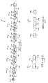
- FIG. 1 is an optical schematic view of an endoscope constructed in accordance with the present invention, wherein three sets of relay lens pairs are disposed between an objective lens and an eye lens.
- FIG. 2 is an optical schematic view of an embodiment of a relay lens of FIG. 1 in accordance with the invention, showing a center lens as a sphere.
- FIG. 3 is an optical schematic view of a relay lens of FIG. 2 showing the center lens as a cylindrical, spherical lens, also showing detached, identical inter-lens spacers.
- FIG. 4 is an optical schematic view of a pair of the relay lenses of FIG. 3, constituting a set of Type 1 relay lenses, showing light rays passing through the set.
- FIG. 5 is an optical schematic view of a a relay lens useful in understanding the present application, also showing detached, identical inter-lens spacers.
- FIG. 6 is an optical schematic view of a pair of the relay lenses of FIG. 5, constituting a set of relay lenses, showing light rays passing through the set.
- the endoscope relay lens of the present invention is suitable for use in standard medical endoscopes of the type disclosed in U.S. Patent 4148551 to MacAnally, which is incorporated herein by reference.
- the relay lens 12a,b,c,d,e,f basically comprises a center lens 14a,b,c,d,e,f with a first end lens 16a,b,c,d,e,f affixed to a first surface 18a,b,c,d,e,f of center lens 14a,b,c,d,e,f and a second end lens 20a,b,c,d,e,f affixed to a second surface 22a,b,c,d,e,f of center lens 14a,b,c,d,e,f.
- relay lenses 12a,b,c,d,e,f are disposed between an objective lens 24 and an eye lens 26.
- objective lens 24 relay lenses 12a,b,c, d,e,f and eye lens 26 share a common central axis 27.
- the relay lenses 12a,b,c,d,e,f are arranged in three sets 28, 30, 32 of relay lens pairs.
- the first set 28 includes a pair of two relay lenses 12a and 12b; the second set includes a pair 12c and 12d; and, the third set includes a pair of relay lenses 12e and 12f.
- FIG. 2 wherein a first end lens 16g and second end lens 20g are shown affixed to center lens 14g when center lens 14g is a sphere.
- the end lenses 16g, 20g are sufficiently long to facilitate manipulation of the relay lens 12g during cementing of the end lenses 16g, 20g to the center lens 14g.
- a first end lens 16g is cemented to a spherical center lens 14g.
- the center lens is polished down to a cylinder by standard optical shop methods.
- the second end lens 20g is aligned properly with the first end lens 16g and center lens 14g and cemented to the center lens 14g in a standard optical "V-block".
- FIG. 2 graphically shows the spherical structure of the center lens 14g in a relay lens 12g and the relatively long end lenses 16g, 20g of all embodiments of the present invention.
- FIG. 3 shows the finished embodiment relay lens 12h, wherein end lenses 16h, 20h are affixed to the cylindrical, spherical center lens 14h. Additionally, detached, identical inter-lens spacers 33a,b are shown in FIG. 3.
- FIG. 4 shows light rays 34 passing through a first set 28 of Type 1 relay lenses 12a, 12b.
- the rays 34 and relay lens set 28 define a specific sequence of eleven optical surfaces shown in vertical lines.
- a first optical surface 36 defines an object plane.
- a second optical surface 38 defines an exterior surface of first end lens 16a.
- a third optical surface 40 defines an interior surface of first end lens 16a.
- a fourth optical surface 42 defines an interior surface of second end lens 20a.
- a fifth optical surface 44 defines an exterior surface of second end lens 20a.
- a sixth optical surface 46 defines an aperture stop plane.
- a seventh optical surface 48 defines an exterior surface of first end lens 16b.
- An eighth optical surface 50 defines an interior surface of first end lens 16b.
- a ninth optical surface 52 defines an interior surface of second end lens 20b.
- a tenth optical surface 54 defines an exterior surface of second end lens 20b.
- An eleventh optical surface 56 defines an image plane.
- a working example of a set of relay lenses is defined with specificity in Table A.
- Tests of the performance characteristics of this working example of a relay lens demonstrate a small fraction of a wavelength of Optical Path Difference (OPD) over the entire image area.
- OPD Optical Path Difference
- the example accumulates less than one wavelength of OPD over several sets.
- Most known relay lenses have at least one wavelength of OPD in some or all of their image area through one set.
- the distance from the first optical surface 36 to the second optical surface 38 is one-half the distance from the fifth optical surface 44 to the seventh optical surface 48; and it is also one-half the distance from the tenth optical surface 54 to the exterior surface 58 of the first end lens 16c of the next relay lens set 30 (as seen in FIG. 1). Consequently, the distance between relay lenses 12a, 12b in a set is the same as the distance between sets of relay lenses 28, 30, 32. Therefore, the length of all inter-lens spacers 33a,b is the same, and the spacers are interchangeable.
- FIGS. 5 and 6 show a different center lens 62 which is not spherical.
- relay lens 60a,b includes center lenses 62a,b first end lenses 64a,b affixed to the center lenses 62a,b and second end lenses 66a,b affixed to center lenses 62a,b.
- Also shown in FIG. 5 are detached, identical inter-lens spacers 67a,b.
- relay lenses 60a,b are arranged in a set 68 of two relay lenses 60a,b.
- eleven optical surfaces are defined by the rays and relay lenses 60 a,b.
- a first optical surface 72 defines an object plane.
- a second optical surface 74 defines an exterior surface of first end lens 64a.
- a third optical surface 76 defines an interior surface of first end lens 64a.
- a fourth optical surface 78 defines an interior surface of second end lens 66a.
- a fifth optical surface 80 defines an exterior surface of second end lens 66a.
- a sixth optical surface 82 defines an aperture stop plane.
- a seventh optical surface 84 defines an exterior surface of first end lens 64b.
- An eighth optical surface 86 defines an interior surface of first end lens 64b.
- a ninth optical surface 88 defines an interior surface of second end lens 66b.
- a tenth optical surface 90 defines an exterior surface of second end lens 66b.
- An eleventh optical surface 92 defines an image plane.
- the working example described in Table B was tested and demonstrated a small fraction of a wavelength of OPD over the entire image area.
- the example accumulates less than one wavelength of OPD over several sets.
- the distance from the first optical surface 72 to the second optical surface 74 is one-half the distance from the fifth optical surface 80 to the seventh optical distance 84; and it is also one-half the distance from the tenth optical surface 90 to the exterior surface of the next relay lens set (not shown). Consequently, the distance between relay lens 60a,b in a set 68 is the same as the distance between sets of relay lens pairs. Therefore, the length of all inter-lens spacers 67a,b is the same, and the spacers are interchangeable.
- relay lenses of the present invention can be utilized in non-medical optical instruments to transmit an image through a rigid or semi-rigid cylinder.
Abstract
Description
- The present invention relates to optical lens systems utilized in medical endoscopes.
- Medical endoscopes are utilized to view specific internal areas of the human body. Typically, endoscopes include a long, thin, rigid, or semi-rigid, optical cylinder affixed to a viewing mechanism. The cylinder is sufficiently narrow to be inserted through natural, or small, surgical body openings. When the endoscope is inserted and positioned for use, an image of the object being viewed is formed at an inserted end of the endoscope by an objective lens. The image passes through a series of relay lenses down the cylinder to an eye lens or video camera at a viewing end of the endoscope.
- The relay lenses must be very narrow and are typically around 2.4 mm to 3.0 mm in diameter, and 20 mm to 30 mm long. Each relay lens is usually made of two or more elements and a pair of two relay lenses make up a set of relay lenses. Most endoscopes require two or more sets of relay lens pairs for proper operation. The number of sets depends on the length and specific requirements of a particular endoscope.
- Additionally, unique optical characteristics of each relay lens require specific spacing distances between a pair of relay lenses within a set, and between sets of relay lens pairs within an endoscope. The required distances are maintained by hollow, cylindrical, inter-lens spacers.
- Known relay lenses generally comprise one or two relatively thin end lenses affixed to a substantially thicker center lens. Where one end lens is affixed to a center lens the resulting relay lens is frequently referred to as a "doublet". And, where two end lenses are affixed to opposed ends of a center lens, the relay lens is referred to as a "triplet". Both doublets and triplets are shown in U.S. Patent 4575195 to Hoogland.
- Problems associated with known relay lenses include the high cost of accurately affixing the end lenses to the center lens. Typically, lenses are assembled within standard optical "V-blocks", but the thin end lens tend to be unstable unless mechanically supported within the "V-blocks" during cementing. The diameter-to-thickness ratio of most end lenses is roughly comparable to that of standard corrective contact lenses. The difficulty of affixing such end lenses is exacerbated in the manufacture of triplets because the end lenses have to be precisely aligned on the opposed ends of the center lens, whereby all three lenses share a common central axis.
- An additional problem associated with known relay lenses is the requirement that the relay lenses and inter-lens spacers be inserted into the optical cylinder of the endoscope in a specific alignment and in a specific order. Frequently, during assembly of the endoscope, relay lenses are put in upside down, or in the wrong sequence. Also, inter-lens spacers are often inserted in the wrong order. The error may not be detected until the endoscope is tested by an end user. Disassembly and extraction of the lenses and spacers is a difficult, time consuming and costly procedure.
- Another problem of known relay lenses is the high cost of manufacture of the end and center lenses. Center lenses, in particular, require very delicate procedures. They are relatively long, extremely thin, and typically made of glass, and therefore crack and break easily. Additionally, precisely curved lens surfaces must be formed on each end surface of the center lens. Moreover, some relay lenses utilize different end lenses attached to the same center lens. Essentially, they require manufacture of three separate lenses for each relay lens.
- Consequently, because of structural limitations, known relay lenses are difficult to fabricate due to the relatively short axial lengths of their end lenses; they require extreme care in assembly within an endoscope due to the varying alignment and space requirements of the relay lenses and inter-lens spacers; and, they are costly to manufacture due to the relatively long axial lengths of their center lenses and the need for multiple lens surfaces.
- In GB-A-1443150 there is disclosed in Fig.4 a lens for transmitting an optical image with a centre lens and two end lenses.
- It is the general object of the present invention to provide an improved endoscope relay lens that overcomes the problems of the prior art.
- It is a more specific object to provide an improved endoscope relay lens that has elements that facilitate assembly of the relay lens due to their relative sizes.
- It is another object to provide an improved endoscope relay lens that facilitates alignment and spacing of the relay lenses within an endoscope.
- It is yet another object to provide an improved endoscope relay lens that has elements that are substantially less expensive to manufacture than the elements of known relay lenses.
- It is still another object to provide an improved endoscope relay lens that has optical performance characteristics that are substantially superior to the performance characteristics of known relay lenses.
- The above and other objects and advantages of this invention will become more readily apparent when the following description is read in conjunction with the accompanying drawings.
- The present invention as defined in claim 1, 3, 5 or 7 relates to a three element relay lens, relay lens sets or a method of fabricating three element relay lenses for transmitting an optical image along a narrow cylinder. Sets cf relay lens pairs are typically secured within a narrow optical cylinder of a medical endoscope.
- In an embodiment, the invention comprises two identical end lenses that are affixed to opposed ends of a center lens. The axial length of each end lens is equal to or greater than one-half its diameter. And, the center lens is spherical so that its radii of curvature are one-half of its axial length.
- In the embodiment, the distance from the object being viewed to the exterior surface of the end lens closest to the object is one-half the distance between relay lenses in a pair, and one-half the distance between sets of relay lens pairs.
- Therefore, the relay lenses are symmetrical about an axis passing through the center of the center lens, perpendicular to the passage of light through the relay lens. Consequently, the relay lenses cannot be improperly inserted into the optical cylinder of an endoscope. They function properly in either axial alignment. Additionally, because the required distance between pairs of relay lenses and sets of relay lens pairs is identical, only one size inter-lens spacer is required. Accordingly, in inserting the relay lenses into the endoscope, an operator simply inserts a relay lens, spacer, relay lens, spacer, etc. An assembly error is virtually impossible because the relay lenses are identical and symmetrical as are the inter-lens spacers.
- In fabrication of the embodiment, the center lens can be made extremely accurately at large volume and low cost because it is made from a ball or sphere. The identical end lenses are made in traditional optical shop methods, but in double quantity, and, therefore, lower cost than non-identical end lenses.
- The cementing operation is greatly facilitated because the end lenses, in particular, are quite long, compared to known end lenses. Therefore, they can lie straight and centered in an optical "V-block" during cementing. With relay lenses of the embodiment, a very advantageous cementing can be utilized by first cementing an end lens anywhere on a sphere of center lens glass. Next, the sphere is polished down to a cylinder having the same diameter as that of the affixed end lens. Then, the delicate operation of properly aligning the last end lens can be undertaken and facilitated through the handling advantages of the long, previously cemented together end lens and center lens.
- FIG. 1 is an optical schematic view of an endoscope constructed in accordance with the present invention, wherein three sets of relay lens pairs are disposed between an objective lens and an eye lens.
- FIG. 2 is an optical schematic view of an embodiment of a relay lens of FIG. 1 in accordance with the invention, showing a center lens as a sphere.
- FIG. 3 is an optical schematic view of a relay lens of FIG. 2 showing the center lens as a cylindrical, spherical lens, also showing detached, identical inter-lens spacers.
- FIG. 4 is an optical schematic view of a pair of the relay lenses of FIG. 3, constituting a set of Type 1 relay lenses, showing light rays passing through the set.
- FIG. 5 is an optical schematic view of a a relay lens useful in understanding the present application, also showing detached, identical inter-lens spacers.
- FIG. 6 is an optical schematic view of a pair of the relay lenses of FIG. 5, constituting a set of relay lenses, showing light rays passing through the set.
- The endoscope relay lens of the present invention is suitable for use in standard medical endoscopes of the type disclosed in U.S. Patent 4148551 to MacAnally, which is incorporated herein by reference.
- Referring to the drawings in detail, an embodiment of a medical endoscope according to the present invention lenses is shown in an optical schematic view in FIG. 1 and generally designated by the reference numeral 10. The
relay lens 12a,b,c,d,e,f basically comprises acenter lens 14a,b,c,d,e,f with afirst end lens 16a,b,c,d,e,f affixed to afirst surface 18a,b,c,d,e,f ofcenter lens 14a,b,c,d,e,f and asecond end lens 20a,b,c,d,e,f affixed to a second surface 22a,b,c,d,e,f ofcenter lens 14a,b,c,d,e,f. In the endoscope of FIG. 1,relay lenses 12a,b,c,d,e,f are disposed between anobjective lens 24 and aneye lens 26. When the endoscope 10 is straight,objective lens 24,relay lenses 12a,b,c, d,e,f andeye lens 26 share a commoncentral axis 27. - The
relay lenses 12a,b,c,d,e,f are arranged in threesets first set 28 includes a pair of tworelay lenses 12a and 12b; the second set includes a pair 12c and 12d; and, the third set includes a pair of relay lenses 12e and 12f. - The distinctive features of the present invention and of the relay lens, in particular, are best shown in FIG. 2, wherein a first end lens 16g and second end lens 20g are shown affixed to center lens 14g when center lens 14g is a sphere. The end lenses 16g, 20g are sufficiently long to facilitate manipulation of the relay lens 12g during cementing of the end lenses 16g, 20g to the center lens 14g. Typically, a first end lens 16g is cemented to a spherical center lens 14g. Next, the center lens is polished down to a cylinder by standard optical shop methods. Then, the second end lens 20g is aligned properly with the first end lens 16g and center lens 14g and cemented to the center lens 14g in a standard optical "V-block".
- FIG. 2 graphically shows the spherical structure of the center lens 14g in a relay lens 12g and the relatively long end lenses 16g, 20g of all embodiments of the present invention. FIG. 3 shows the finished
embodiment relay lens 12h, whereinend lenses spherical center lens 14h. Additionally, detached, identicalinter-lens spacers 33a,b are shown in FIG. 3. - FIG. 4 shows light rays 34 passing through a
first set 28 of Type 1relay lenses 12a, 12b. Therays 34 and relay lens set 28 define a specific sequence of eleven optical surfaces shown in vertical lines. A firstoptical surface 36 defines an object plane. A secondoptical surface 38 defines an exterior surface offirst end lens 16a. A thirdoptical surface 40 defines an interior surface offirst end lens 16a. A fourthoptical surface 42 defines an interior surface ofsecond end lens 20a. A fifthoptical surface 44 defines an exterior surface ofsecond end lens 20a. A sixthoptical surface 46 defines an aperture stop plane. A seventhoptical surface 48 defines an exterior surface of first end lens 16b. An eighthoptical surface 50 defines an interior surface of first end lens 16b. A ninthoptical surface 52 defines an interior surface of second end lens 20b. A tenthoptical surface 54 defines an exterior surface of second end lens 20b. An eleventhoptical surface 56 defines an image plane. - A working example of a set of relay lenses is defined with specificity in Table A.
TABLE A McKINLEY RELAY LENS SET, SURFACE RADIUS THICKNESS GLASS 36 -- 3.000 38 8.525 6.787 SF8 40 3.000 6.000 SSKN8 42 -3.000 6.787 SF8 44 -8.525 3.000 AIR 46 -- 3.000 AIR 48 8.525 6.787 SF8 50 3.000 6.000 SSKN8 52 -3.000 6.787 SF8 54 -8.525 3.000 AIR 56 -- -- AIR - In Table A, the numerical value in the columns under "RADIUS" and "THICKNESS" are in millimeters. The "GLASS" descriptions are standard optical glass characterizations as found in the product catalog of the Schott Glass Company of the Federal Republic of Germany. The column "THICKNESS" refers to the distance to the next optical surface. For example, in line with
surface 36, the number "3.000" means 3.000 mm to surface 38. The column "RADIUS" refers to the radii of curvature of the respective curved surfaces. In this working example, the lens diameters are 3.000 mm and the overall object-to-image distance is 51.148 mm. The object and image diameters are 1.70 mm. - Tests of the performance characteristics of this working example of a relay lens demonstrate a small fraction of a wavelength of Optical Path Difference (OPD) over the entire image area. The example accumulates less than one wavelength of OPD over several sets. Most known relay lenses have at least one wavelength of OPD in some or all of their image area through one set.
- In the working example described in Table A and FIGS 4 and 1, the distance from the first
optical surface 36 to the secondoptical surface 38 is one-half the distance from the fifthoptical surface 44 to the seventhoptical surface 48; and it is also one-half the distance from the tenthoptical surface 54 to theexterior surface 58 of the first end lens 16c of the next relay lens set 30 (as seen in FIG. 1). Consequently, the distance betweenrelay lenses 12a, 12b in a set is the same as the distance between sets ofrelay lenses inter-lens spacers 33a,b is the same, and the spacers are interchangeable. - FIGS. 5 and 6 show a different center lens 62 which is not spherical. As seen in FIGS. 5 and 6, relay lens 60a,b includes
center lenses 62a,bfirst end lenses 64a,b affixed to thecenter lenses 62a,b andsecond end lenses 66a,b affixed tocenter lenses 62a,b. Also shown in FIG. 5 are detached, identicalinter-lens spacers 67a,b. - As seen in FIG. 6, relay lenses 60a,b are arranged in a
set 68 of two relay lenses 60a,b. Like relay sets 28, 30, 32 according to the invention, when light rays 70 pass through theset 68, eleven optical surfaces are defined by the rays and relay lenses 60 a,b. A firstoptical surface 72 defines an object plane. A secondoptical surface 74 defines an exterior surface offirst end lens 64a. A thirdoptical surface 76 defines an interior surface offirst end lens 64a. A fourthoptical surface 78 defines an interior surface ofsecond end lens 66a. A fifthoptical surface 80 defines an exterior surface ofsecond end lens 66a. A sixthoptical surface 82 defines an aperture stop plane. A seventhoptical surface 84 defines an exterior surface of first end lens 64b. An eighthoptical surface 86 defines an interior surface of first end lens 64b. A ninthoptical surface 88 defines an interior surface of second end lens 66b. A tenthoptical surface 90 defines an exterior surface of second end lens 66b. An eleventhoptical surface 92 defines an image plane. - A working example of a set of relay lenses is defined with specificity in Table B.
TABLE B LENS DATA McKINLEY RELAY LENS SET, SURFACE RADIUS THICKNESS GLASS 72 -- 3.000 74 7.188 5.000 F4 76 2.710 8.258 BAK2 78 -2.710 5.000 F4 80 -7.188 3.000 AIR 82 -- 3.000 AIR 84 7.188 5.000 F4 86 2.710 8.258 BAK2 88 -2.710 5.000 F4 90 -7.188 3.000 AIR 92 -- -- AIR - In Table B, the numerical values in the columns under "RADIUS" and "THICKNESS" are in millimeters. The "GLASS" descriptions are standard optical glass characterizations as found in the product catalog of the Schott Glass Company of the Federal Republic of Germany. As in Table A, the column "THICKNESS" refers to the distance to the next optical surface. The column "RADIUS" refers to the radii of curvature of the respective curved surfaces. In this working example, the lens diameters are 3.000 mm and the overall object-to-image distance is 48.516 mm. The object and image diameters are 1.70 mm.
- As with the example according to the invention described in Table A, the working example described in Table B was tested and demonstrated a small fraction of a wavelength of OPD over the entire image area. The example accumulates less than one wavelength of OPD over several sets.
- In the working example of a relay lens set described in Table B, and FIG. 6, the distance from the first
optical surface 72 to the secondoptical surface 74 is one-half the distance from the fifthoptical surface 80 to the seventhoptical distance 84; and it is also one-half the distance from the tenthoptical surface 90 to the exterior surface of the next relay lens set (not shown). Consequently, the distance between relay lens 60a,b in aset 68 is the same as the distance between sets of relay lens pairs. Therefore, the length of allinter-lens spacers 67a,b is the same, and the spacers are interchangeable. - It is to be understood that the working example described in Tables A is not to be construed as limitations on the present invention. A variety of paper examples has also demonstrated performance characteristics comparable to the aforesaid working example of the invention, while retaining end lenses whose axial lengths are equal to or greater than one-half their diameters, thereby facilitating manipulation of the end and center lenses during fabrication and assembly. The paper examples also define the same relay lens symmetry , for ease of alignment during endoscope assembly. And, those paper examples also include the optical performance characteristics that produce identical spacing requirements between a pair of relay lenses in a set, and between sets of relay lens.
- It should also be understood by those skilled in the art that obvious structural modifications can be made without departing from the invention as defined in the claims. For example, the relay lenses of the present invention can be utilized in non-medical optical instruments to transmit an image through a rigid or semi-rigid cylinder.
Claims (7)
- A three element relay lens (12a) for transmitting an optical image, that comprises:(a) a centre lens (14a),(b) two identical end lenses (16a, 20a) affixed to opposed ends of the centre lens, the end lenses and centre lens forming a cylinder, each of said end lenses having an axial length that is equal to or greater than one-half its diameter, so that the relay lens is symmetrical about a plane passing through the centre of the centre lens perpendicular to an axis passing through the centres of the opposed end lenses, the radii of curvature of the opposed ends of the centre lens being identical and equal to one half of the maximum axial length of the centre lens; the three element relay lens being operative to provide image transmission therethrough such that an object located at an object plane adjacent one of the end lenses is imaged to an image plane adjacent the other end lens.
- The three element relay lens of Claim 1 wherein the center lens is spherical, so that radii of curvature of the opposed ends of the center lens are one-half of the axial length of the center lens.
- A relay lens set (28) for transmitting an optical image of an object, that comprises a pair of identical three element relay lenses (12a,12b) as claimed in Claim 1, wherein radii of curvature and axial lengths of the end lenses and center lens cooperate so that optimal performance of the relay lens set is achieved when the distance from the object to the closest relay lens is one-half the distance between the pair of relay lenses in the set.
- The relay lens set of Claim 3 wherein the relay lens set transmits an optical image to a second, identical relay lens set (30) and the distance from the object to the closest relay lens is one-half the distance between the relay lens set and the second relay lens set.
- A relay lens set system for transmitting an optical image of an object through a plurality of three element relay lenses as claimed in Claim 1, wherein radii of curvature and axial lengths of the end lenses and center lens cooperate so that optimal performance of the relay lens set system is achieved when the distance from the object to the closest relay lens is one-half the distance between the pair of relay lenses in the first relay lens set and one-half the distance between the first and second relay lens sets.
- The relay lens set system of Claim 5, wherein the distance from the object to the closest relay lens is one-half the distance between any adjacent relay lens sets.
- A method of fabricating three element relay lenses which comprises the steps of:(a) cementing a first, cylindrical end lens to an optical glass sphere, said cylindrical end lens having an axial length that is greater or equal to one-half its diameter;(b) polishing the sphere so that it forms a cylinder and coincides with the cylindrical dimensions of the first end lens; and(c) cementing a second, identical, cylindrical end lens to an end of the cylinder formed by the first end lens and polished sphere, so that the first and second end lenses are cemented to opposed ends of the polished sphere and the first end lens, polished sphere and second end lens share a common central axis.
Applications Claiming Priority (2)
| Application Number | Priority Date | Filing Date | Title |
|---|---|---|---|
| US07/507,877 US5059009A (en) | 1990-04-12 | 1990-04-12 | Endoscope relay lens |
| US507877 | 1990-04-12 |
Publications (2)
| Publication Number | Publication Date |
|---|---|
| EP0452053A1 EP0452053A1 (en) | 1991-10-16 |
| EP0452053B1 true EP0452053B1 (en) | 1997-10-22 |
Family
ID=24020486
Family Applications (1)
| Application Number | Title | Priority Date | Filing Date |
|---|---|---|---|
| EP91303038A Expired - Lifetime EP0452053B1 (en) | 1990-04-12 | 1991-04-05 | Endoscope relay lens |
Country Status (11)
| Country | Link |
|---|---|
| US (1) | US5059009A (en) |
| EP (1) | EP0452053B1 (en) |
| JP (1) | JP2534409B2 (en) |
| AT (1) | ATE159594T1 (en) |
| AU (1) | AU7414191A (en) |
| CA (1) | CA2039570C (en) |
| DE (1) | DE69127988T2 (en) |
| IE (1) | IE80722B1 (en) |
| NO (1) | NO911412L (en) |
| NZ (1) | NZ237778A (en) |
| ZA (1) | ZA912709B (en) |
Families Citing this family (23)
| Publication number | Priority date | Publication date | Assignee | Title |
|---|---|---|---|---|
| US5188092A (en) * | 1990-12-13 | 1993-02-23 | United States Surgical Corporation | Disposable rigid endoscope |
| US5731916A (en) * | 1991-01-16 | 1998-03-24 | Olympus Optical Co., Ltd. | Image Transmitting optical system |
| AU3721993A (en) * | 1992-02-19 | 1993-09-13 | United States Surgical Corporation | Optical viewing device |
| US5416634A (en) * | 1992-09-11 | 1995-05-16 | United States Surgical Corporation | Optical viewing device |
| US5369525A (en) * | 1992-12-02 | 1994-11-29 | United States Surgical Corporation | Ring lens assembly for an optical viewing device |
| US5751341A (en) * | 1993-01-05 | 1998-05-12 | Vista Medical Technologies, Inc. | Stereoscopic endoscope system |
| CA2123077C (en) * | 1994-04-14 | 2001-09-04 | Anthony B. Greening | Single lens stereoscopic imaging system |
| US5633754A (en) * | 1994-12-06 | 1997-05-27 | Hoogland; Jan | Integrated optical system for endoscopes and the like |
| US6853485B2 (en) | 1994-12-06 | 2005-02-08 | Jan Hoogland | Integrated optical system for endoscopes and the like |
| US5613936A (en) * | 1995-02-22 | 1997-03-25 | Concurrent Technologies Corp. | Stereo laparoscope apparatus |
| US5976076A (en) * | 1995-02-22 | 1999-11-02 | Kolff; Jack | Stereo laparoscope with synchronized optics |
| US6144762A (en) * | 1998-02-23 | 2000-11-07 | Olympus America Inc. | Stereo video microscope |
| US6163640A (en) * | 1998-06-01 | 2000-12-19 | Metroptic Technologies, Inc. | Stereoscopic sensor |
| DE19910050C2 (en) * | 1999-03-08 | 2003-08-14 | Storz Karl Gmbh & Co Kg | Image transmission system for endoscopes and the like periscopes and method for producing an image transmission system |
| US6767321B2 (en) | 1999-10-04 | 2004-07-27 | Robert Czarnek | Stereo laparoscope with discrete working distance |
| US6490085B1 (en) | 2001-02-21 | 2002-12-03 | Richard Wolf Gmbh | Symmetric anastigmatic endoscope relay system |
| US8982203B2 (en) | 2007-06-06 | 2015-03-17 | Karl Storz Gmbh & Co. Kg | Video system for viewing an object on a body |
| US8081364B2 (en) * | 2007-11-27 | 2011-12-20 | Duke University | High-speed multi-dimensional beam scanning system with angle amplification |
| CN102725688B (en) | 2009-07-10 | 2015-04-01 | 管理前街不同收入阶层的前街投资管理有限公司 | Method and apparatus for generating three dimensional image information using a single imaging path |
| US9433341B2 (en) * | 2012-03-26 | 2016-09-06 | Karl Storz Imaging, Inc. | Compensated relays for reducing number of elements in rod lens endoscopes |
| JPWO2019239578A1 (en) * | 2018-06-15 | 2021-07-01 | オリンパス株式会社 | Objective optical system and optical system for rigid mirrors using it, rigid mirror |
| US20220160232A1 (en) * | 2019-03-18 | 2022-05-26 | The Regents Of The University Of Michigan | Ultra-compact microsystems-based single axis confocal endomicroscope |
| CN111904373A (en) * | 2020-09-04 | 2020-11-10 | 鹰利视医疗科技有限公司 | 4 clear peritoneoscope of K superelevation changes image mirror structure |
Family Cites Families (14)
| Publication number | Priority date | Publication date | Assignee | Title |
|---|---|---|---|---|
| US2828669A (en) * | 1953-07-14 | 1958-04-01 | George P Pilling & Son Company | Lens system for endoscopes |
| GB1443150A (en) * | 1972-12-06 | 1976-07-21 | Nat Res Dev | Optical devices |
| US4168882A (en) * | 1975-04-30 | 1979-09-25 | The Secretary Of State For Social Services In Her Britannic Majesty's Government Of The United Kingdom Of Great Britain And Northern Ireland | Optical systems |
| US4148550A (en) * | 1977-05-09 | 1979-04-10 | American Hospital Supply Corporation | Rod lens assembly and method of making the same |
| US4148551A (en) * | 1977-05-09 | 1979-04-10 | American Hospital Supply Corporation | Modular rod lens assembly and method of making the same |
| US4158475A (en) * | 1978-04-18 | 1979-06-19 | American Optical Corporation | Optical system for inverted microscopes |
| US4358810A (en) * | 1981-01-21 | 1982-11-09 | Westinghouse Electric Corp. | Circuit breaker with alarm |
| US4575195A (en) * | 1981-05-29 | 1986-03-11 | Jan Hoogland | Flat field lenses |
| US4545652A (en) * | 1981-05-29 | 1985-10-08 | Jan Hoogland | Flat field lenses |
| JPS5913721A (en) * | 1982-07-15 | 1984-01-24 | Tsurui Yakuhin Kogyo Kk | Agent for suppressing formation of bacterial plaque on tooth |
| JPS6042728A (en) * | 1983-08-18 | 1985-03-07 | Olympus Optical Co Ltd | Image forming optical system |
| JPH0823625B2 (en) * | 1985-07-25 | 1996-03-06 | オリンパス光学工業株式会社 | Image transmission optical system using inhomogeneous lens |
| US4779613A (en) * | 1986-03-13 | 1988-10-25 | Olympus Optical Co., Ltd. | Endoscope with means for preventing an observing optical system from being fogged |
| US4993817A (en) * | 1988-05-09 | 1991-02-19 | Jan Hoogland | Endoscope relay optics |
-
1990
- 1990-04-12 US US07/507,877 patent/US5059009A/en not_active Expired - Lifetime
-
1991
- 1991-04-02 CA CA002039570A patent/CA2039570C/en not_active Expired - Fee Related
- 1991-04-05 DE DE69127988T patent/DE69127988T2/en not_active Expired - Fee Related
- 1991-04-05 EP EP91303038A patent/EP0452053B1/en not_active Expired - Lifetime
- 1991-04-05 AT AT91303038T patent/ATE159594T1/en active
- 1991-04-08 AU AU74141/91A patent/AU7414191A/en not_active Abandoned
- 1991-04-10 IE IE119691A patent/IE80722B1/en unknown
- 1991-04-10 NZ NZ237778A patent/NZ237778A/en unknown
- 1991-04-11 NO NO91911412A patent/NO911412L/en unknown
- 1991-04-11 ZA ZA912709A patent/ZA912709B/en unknown
- 1991-04-12 JP JP3108904A patent/JP2534409B2/en not_active Expired - Fee Related
Also Published As
| Publication number | Publication date |
|---|---|
| DE69127988T2 (en) | 1998-03-12 |
| IE80722B1 (en) | 1998-12-30 |
| NO911412L (en) | 1991-10-14 |
| NZ237778A (en) | 1994-06-27 |
| DE69127988D1 (en) | 1997-11-27 |
| CA2039570A1 (en) | 1991-10-13 |
| CA2039570C (en) | 1995-11-28 |
| AU7414191A (en) | 1991-10-17 |
| JP2534409B2 (en) | 1996-09-18 |
| ZA912709B (en) | 1992-01-29 |
| US5059009A (en) | 1991-10-22 |
| IE911196A1 (en) | 1991-10-23 |
| NO911412D0 (en) | 1991-04-11 |
| ATE159594T1 (en) | 1997-11-15 |
| EP0452053A1 (en) | 1991-10-16 |
| JPH04230702A (en) | 1992-08-19 |
Similar Documents
| Publication | Publication Date | Title |
|---|---|---|
| EP0452053B1 (en) | Endoscope relay lens | |
| US5097359A (en) | Endoscope relay lens configuration | |
| US5519532A (en) | Disposable endoscope | |
| US5892630A (en) | Disposable endoscope | |
| US4984878A (en) | Ojective lens for endoscope | |
| US4168882A (en) | Optical systems | |
| US7885010B1 (en) | Endoscope objective lens and method of assembly | |
| US5377047A (en) | Disposable endoscope employing positive and negative gradient index of refraction optical materials | |
| US7621868B2 (en) | Convergence optics for stereoscopic imaging systems | |
| US5933275A (en) | Optical system for non-flexible endoscopes | |
| EP3064977A1 (en) | Image pickup device | |
| US5980453A (en) | Endoscope with low distortion | |
| US4735491A (en) | Optical system for endoscopes | |
| EP0609093A1 (en) | Negative abbe number radial gradient index relay, method of making, and use of same | |
| EP3828612B1 (en) | Lens system for a video endoscope, endoscope objective, video endoscope, and assembly method | |
| US6490085B1 (en) | Symmetric anastigmatic endoscope relay system | |
| EP2056150A1 (en) | Transmissive optical element and optical system using the same | |
| US6853485B2 (en) | Integrated optical system for endoscopes and the like | |
| CA1058436A (en) | Elongated rod lens optical system | |
| US5891015A (en) | Endoscope including a front lens group and an inner lens group forming a telesystem | |
| US9696537B2 (en) | Opto-mechanical devices with sharp-edge lenses | |
| US5589989A (en) | Compact objective lens system | |
| US4497546A (en) | Wide-field eyepiece | |
| US5625488A (en) | Telecentric relay lens system | |
| US5572369A (en) | Triplet-type lens for use in a compact photographic camera |
Legal Events
| Date | Code | Title | Description |
|---|---|---|---|
| PUAI | Public reference made under article 153(3) epc to a published international application that has entered the european phase |
Free format text: ORIGINAL CODE: 0009012 |
|
| AK | Designated contracting states |
Kind code of ref document: A1 Designated state(s): AT BE CH DE DK ES FR GB GR IT LI LU NL SE |
|
| 17P | Request for examination filed |
Effective date: 19920415 |
|
| 17Q | First examination report despatched |
Effective date: 19931110 |
|
| GRAG | Despatch of communication of intention to grant |
Free format text: ORIGINAL CODE: EPIDOS AGRA |
|
| GRAH | Despatch of communication of intention to grant a patent |
Free format text: ORIGINAL CODE: EPIDOS IGRA |
|
| GRAH | Despatch of communication of intention to grant a patent |
Free format text: ORIGINAL CODE: EPIDOS IGRA |
|
| GRAA | (expected) grant |
Free format text: ORIGINAL CODE: 0009210 |
|
| AK | Designated contracting states |
Kind code of ref document: B1 Designated state(s): AT BE CH DE DK ES FR GB GR IT LI LU NL SE |
|
| ITF | It: translation for a ep patent filed |
Owner name: STUDIO AVV. LIA STELLA |
|
| PG25 | Lapsed in a contracting state [announced via postgrant information from national office to epo] |
Ref country code: LI Free format text: LAPSE BECAUSE OF FAILURE TO SUBMIT A TRANSLATION OF THE DESCRIPTION OR TO PAY THE FEE WITHIN THE PRESCRIBED TIME-LIMIT Effective date: 19971022 Ref country code: GR Free format text: LAPSE BECAUSE OF FAILURE TO SUBMIT A TRANSLATION OF THE DESCRIPTION OR TO PAY THE FEE WITHIN THE PRESCRIBED TIME-LIMIT Effective date: 19971022 Ref country code: ES Free format text: THE PATENT HAS BEEN ANNULLED BY A DECISION OF A NATIONAL AUTHORITY Effective date: 19971022 Ref country code: DK Free format text: LAPSE BECAUSE OF NON-PAYMENT OF DUE FEES Effective date: 19971022 Ref country code: CH Free format text: LAPSE BECAUSE OF FAILURE TO SUBMIT A TRANSLATION OF THE DESCRIPTION OR TO PAY THE FEE WITHIN THE PRESCRIBED TIME-LIMIT Effective date: 19971022 Ref country code: BE Free format text: LAPSE BECAUSE OF FAILURE TO SUBMIT A TRANSLATION OF THE DESCRIPTION OR TO PAY THE FEE WITHIN THE PRESCRIBED TIME-LIMIT Effective date: 19971022 Ref country code: AT Free format text: LAPSE BECAUSE OF FAILURE TO SUBMIT A TRANSLATION OF THE DESCRIPTION OR TO PAY THE FEE WITHIN THE PRESCRIBED TIME-LIMIT Effective date: 19971022 |
|
| REF | Corresponds to: |
Ref document number: 159594 Country of ref document: AT Date of ref document: 19971115 Kind code of ref document: T |
|
| REG | Reference to a national code |
Ref country code: CH Ref legal event code: EP |
|
| REF | Corresponds to: |
Ref document number: 69127988 Country of ref document: DE Date of ref document: 19971127 |
|
| ET | Fr: translation filed | ||
| PG25 | Lapsed in a contracting state [announced via postgrant information from national office to epo] |
Ref country code: SE Effective date: 19980122 |
|
| PG25 | Lapsed in a contracting state [announced via postgrant information from national office to epo] |
Ref country code: LU Free format text: LAPSE BECAUSE OF NON-PAYMENT OF DUE FEES Effective date: 19980405 |
|
| PGFP | Annual fee paid to national office [announced via postgrant information from national office to epo] |
Ref country code: NL Payment date: 19980430 Year of fee payment: 8 |
|
| REG | Reference to a national code |
Ref country code: CH Ref legal event code: PL |
|
| PLBE | No opposition filed within time limit |
Free format text: ORIGINAL CODE: 0009261 |
|
| STAA | Information on the status of an ep patent application or granted ep patent |
Free format text: STATUS: NO OPPOSITION FILED WITHIN TIME LIMIT |
|
| 26N | No opposition filed | ||
| PG25 | Lapsed in a contracting state [announced via postgrant information from national office to epo] |
Ref country code: NL Free format text: LAPSE BECAUSE OF NON-PAYMENT OF DUE FEES Effective date: 19991101 |
|
| NLV4 | Nl: lapsed or anulled due to non-payment of the annual fee |
Effective date: 19991101 |
|
| PGFP | Annual fee paid to national office [announced via postgrant information from national office to epo] |
Ref country code: GB Payment date: 20010327 Year of fee payment: 11 |
|
| PGFP | Annual fee paid to national office [announced via postgrant information from national office to epo] |
Ref country code: FR Payment date: 20010412 Year of fee payment: 11 |
|
| REG | Reference to a national code |
Ref country code: GB Ref legal event code: IF02 |
|
| PG25 | Lapsed in a contracting state [announced via postgrant information from national office to epo] |
Ref country code: GB Free format text: LAPSE BECAUSE OF NON-PAYMENT OF DUE FEES Effective date: 20020405 |
|
| GBPC | Gb: european patent ceased through non-payment of renewal fee |
Effective date: 20020405 |
|
| PG25 | Lapsed in a contracting state [announced via postgrant information from national office to epo] |
Ref country code: FR Free format text: LAPSE BECAUSE OF NON-PAYMENT OF DUE FEES Effective date: 20021231 |
|
| REG | Reference to a national code |
Ref country code: FR Ref legal event code: ST |
|
| PG25 | Lapsed in a contracting state [announced via postgrant information from national office to epo] |
Ref country code: IT Free format text: LAPSE BECAUSE OF NON-PAYMENT OF DUE FEES;WARNING: LAPSES OF ITALIAN PATENTS WITH EFFECTIVE DATE BEFORE 2007 MAY HAVE OCCURRED AT ANY TIME BEFORE 2007. THE CORRECT EFFECTIVE DATE MAY BE DIFFERENT FROM THE ONE RECORDED. Effective date: 20050405 |
|
| PGFP | Annual fee paid to national office [announced via postgrant information from national office to epo] |
Ref country code: DE Payment date: 20060419 Year of fee payment: 16 |
|
| PG25 | Lapsed in a contracting state [announced via postgrant information from national office to epo] |
Ref country code: DE Free format text: LAPSE BECAUSE OF NON-PAYMENT OF DUE FEES Effective date: 20071101 |