EP0452046A2 - Aimant supraconducteur - Google Patents
Aimant supraconducteur Download PDFInfo
- Publication number
- EP0452046A2 EP0452046A2 EP91303013A EP91303013A EP0452046A2 EP 0452046 A2 EP0452046 A2 EP 0452046A2 EP 91303013 A EP91303013 A EP 91303013A EP 91303013 A EP91303013 A EP 91303013A EP 0452046 A2 EP0452046 A2 EP 0452046A2
- Authority
- EP
- European Patent Office
- Prior art keywords
- magnet
- vacuum vessel
- cartridge
- magnet cartridge
- axial
- Prior art date
- Legal status (The legal status is an assumption and is not a legal conclusion. Google has not performed a legal analysis and makes no representation as to the accuracy of the status listed.)
- Withdrawn
Links
Images


Classifications
-
- G—PHYSICS
- G01—MEASURING; TESTING
- G01R—MEASURING ELECTRIC VARIABLES; MEASURING MAGNETIC VARIABLES
- G01R33/00—Arrangements or instruments for measuring magnetic variables
- G01R33/20—Arrangements or instruments for measuring magnetic variables involving magnetic resonance
- G01R33/28—Details of apparatus provided for in groups G01R33/44 - G01R33/64
- G01R33/38—Systems for generation, homogenisation or stabilisation of the main or gradient magnetic field
- G01R33/381—Systems for generation, homogenisation or stabilisation of the main or gradient magnetic field using electromagnets
- G01R33/3815—Systems for generation, homogenisation or stabilisation of the main or gradient magnetic field using electromagnets with superconducting coils, e.g. power supply therefor
-
- G—PHYSICS
- G01—MEASURING; TESTING
- G01R—MEASURING ELECTRIC VARIABLES; MEASURING MAGNETIC VARIABLES
- G01R33/00—Arrangements or instruments for measuring magnetic variables
- G01R33/20—Arrangements or instruments for measuring magnetic variables involving magnetic resonance
- G01R33/28—Details of apparatus provided for in groups G01R33/44 - G01R33/64
- G01R33/38—Systems for generation, homogenisation or stabilisation of the main or gradient magnetic field
- G01R33/3802—Manufacture or installation of magnet assemblies; Additional hardware for transportation or installation of the magnet assembly or for providing mechanical support to components of the magnet assembly
Definitions
- the present invention relates to superconductive magnets.
- An illustrative embodiment of the present invention relates to radial support systems for refrigerated magnetic resonance magnets.
- cryostat systems which have a light weight, thin walled thermal shield cooled by a cryocooler, it is advantageous to support the thermal shield from the magnet cartridge. This allows the magnet cartridge and thermal shield to be assembled together prior to insertion in the vacuum vessel.
- the magnet cartridge which is the primary mass within the enclosure, is independently supported by the vacuum vessel.
- the supports In order to minimize the conduction heat leak from the vacuum vessel and thermal shield to the magnet cartridge, it is necessary to use supports made with low thermal conductivity materials, minimized cross sectional area, and maximized length.
- the supports must be designed to minimize the deformation of the magnet cartridge and the thermal shield due to the reaction forces at the attachment points of the supports.
- the supports must permit the axial and radial positioning of the magnet cartridge and the thermal shield within the vacuum vessel.
- the adjustment mechanisms must be compatible with the overall cryostat assembly procedure.
- the supports must be capable of withstanding the forces due to the dynamic shock loading of the system during shipping and handling. Shock loads during shipping have been measured at approximately 2g vertical, and 1g horizontal.
- the magnet cartridge typically expands radially due to magnetic forces. There must be no frictional heating between the magnet cartridge and the supports during ramp up, as this could induce a local temperature rise in the magnet and lead to a magnet quench (transition from superconducting to normal resistance in the superconductive windings).
- a superconductive MR magnet including a generally cylindrical vacuum vessel defining an axially extending bore.
- a magnet cartridge having a cylindrical shape is situated in the vacuum vessel concentric with and spaced away from the bore of the magnet.
- An axial magnet cartridge support comprising a first tension rod is affixed to one end of the magnet cartridge and extends axially along the magnet cartridge, radially spaced away therefrom, and is affixed to the vacuum vessel by tension adjusting means.
- a second tension rod affixed to the opposite end of the magnet cartridge extends axially along the magnet cartridge radially spaced away therefrom, and is affixed to the vacuum vessel by tension adjusting means.
- Each of the rods limit axial motion in one direction.
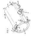
- a refrigerated superconductive magnetic resonance (MR) magnet 11 is shown.
- the magnet includes a cylindrical vacuum vessel 13 having an axially extending bore 15. Located inside the vacuum vessel is a cylindrical magnet cartridge 17 surrounded by a thermal radiation shield 21.
- the magnet cartridge contains a plurality of windings symmetrically disposed about the axial centerline of the cartridge.
- three pairs of superconductive Nb3Sn windings are wound on a fiberglass reinforced form which has been machined by provide circumferential slots for winding the superconductive coils and axial slots for electrical bus bars connecting the coils together.
- a winding of this type is shown and claimed in copending application entitled "Superconductive Quench Protected Magnet Coil", Serial No. 07/215,479, EP-A-0350264 (RD-18896), and hereby incorporated by reference.
- a stainless steel end ring 23 is affixed to either end of the cartridge by threaded bolts and epoxy resin bonding.
- the vacuum vessel has a cylindrical extension 25 which protrudes radially outwardly from the vacuum vessel in the horizontal direction.
- the central axis of the extension lies on a radial line extending through the axial midplane of the vacuum vessel.
- the cylindrical extension has an annular shaped cover 27.
- a two stage cryocooler 31 is mounted to the cover with the cold end of the cryocooler extending inside the vacuum vessel.
- the cryocooler 31 is mounted using aninterface of the type shown and claimed in U.S. Patent 4930318 (RD-19514) entitled "Cryocooler Cold Head Interface Receptacle".
- the cryocooler cold end 32 visible in Fig. 2, typically transmits a force of approximately 1000 pounds on the center portion of the magnet cartridge when the vacuum vessel is evacuated.
- the vacuum vessel and the cylindrical extension can be fabricated from carbon steel with the bore sleeve fabricated from stainless steel, for example.
- magnet cartridge radial struts supporting the magnet cartridge from the vacuum vessel.
- Two of the struts are arranged in the vertical direction and are affixed at either axial end of the magnet cartridge in the horizontal plane on the side of the cartridge opposite the cryocooler.
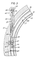
- Vertical strut 33 is shown in Figure 3.
- Four of the magnet cartridge struts extend laterally.
- Two lateral struts 35 and 37 are shown in Figure 2 and are affixed to one end of the magnet cartridge above and below the horizontal plane forming an acute angle when measured from the horizontal plane.
- the other end of both struts 35 and 37 are affixed to the vacuum vessel with strut 35 extending upwards at an angle and strut 37 extending downwards at an angle toward the vacuum vessel.
- the other two lateral struts are affixed to the other axial end of the magnet cartridge above and below the horizontal plane symmetrically located about the horizontal midplane of the vacuum vessel on the cryocooler side of the magnet.
- Each of the magnet cartridge radial struts comprise a thin walled, G-10 fiberglass epoxy cylinder 39 which has internal threads machined in either end.
- the central portion of the fiberglass cylinder is machined to reduce its outside diameter or wall thickness and therefore its heat conductance.
- the transition between the narrow central portion and the ends has a 3/8 inch radius stress riser.
- the threads in either end stop one quarter of an inch before the reduced diameter portion of the cylinder begins.
- Threaded into either end of the fiberglass epoxy cylinder is a multiaxis joint 41 such as a ball joint of the type available from Aurora Bearing Corp., Aurora, IL.
- the struts are secured to the magnet cartridge by axially extending shoulder bolts 43 passing through the multiaxis joint threadingly engaging ring 23.
- each of the radial struts is attached to a clevis 45.
- the vertical struts each pass through openings in the thermal shield and the vacuum vessel, and are surrounded by vertical cylindrical extensions 47 and 49 and the vacuum vessel.
- the lateral struts each pass through openings in the thermal shield and vacuum vessel and are surrounded by cylindrical extensions 51, 52, 53 and 54.
- Part of the clevis 45 is used to close off the end of the cylindrical extension.
- the lateral extending radial struts pass through openings in the vacuum vessel and through cylindrical extensions closed off by a portion of the clevis which is attached to the ends of the strut.
- the vertical and lateral struts are thermally stationed to the thermal shield 21 at an intermediate location in order to intercept some of the conduction heat from the vacuum vessel which is at ambient temperature and carry it to the shield which is cooled to approximately 40°K by the cryocooler 31.
- the thermal shield can be fabricated from a heat conductive material such as aluminum. Copper braid 55 is epoxy bonded to the strut and soldered or bolted (with an appropriate interface material) to the shield to conduct the heat from the strut to the shield.
- the two vertical support struts 33 support half of the weight of the magnet cartridge 17.
- the magnet cartridge in a 0.5T magnet typically weighs approximately 1,000 lbs.
- the two pairs of lateral struts 35 and 37 react against the contact force of the cryocooler cold head and support half of the weight of the cartridge.
- the multiaxis joints 41 of the vertical supports pivot to allow the magnet cartridge axial centerline to move due to the thermal shrinkage towards the cryocooler 31 during cool down.
- the lateral struts do not permit unrestricted motion in the radial direction in the horizontal plane.
- the initial position of the magnet cartridge is offset so that when shrinkage of the magnet cartridge occurs, the vertical struts will be in the vertical position.
- the magnet cartridge shrinks radially inward when cooled.
- the lateral struts prevent movement of one side of the magnet cartridge, the center and opposite side of the magnet cartridge move towards the cryocooler. All the radial struts are attached to the magnet cartridge near the horizontal center plane in order to minimize the sag of the cartridge due to its own weight.
- the magnet cartridge 17 and thermal shield 21 are positioned in the vacuum vessel 13.
- the clevises 45 are affixed to the warm end of the struts, and are positioned through the cylindrical extensions into the vacuum vessel.
- the thermal braid heat stations 55 are attached to the thermal shield and the struts are secured to the magnet cartridge using shoulder bolts 43.
- the cryocooler 31 is installed, or a radially inward force equivalent to the crycooler is imposed on the magnet cartridge when the radial struts are adjusted. Alternatively, the cryocooler is not installed, but the deformation of the magnet cartridge is anticipated during radial strut adjustment.
- the radial struts carry the radial load while being adjusted.
- the clevises are rotated to achieve radial adjustment of the magnet cartridge position. Rotating the clevis adjusts the overall length between the threaded multiaxis supports of each strut. When the radial adjustment is achieved, each clevis mount is welded to each end of the cylindrical extension to form a vacuum seal.
- the angle chosen for the lateral struts depends on the load imposed, as well as the length of the strut desired to minimize the conduction heat load to the magnet cartridge. A longer strut provides less heat conduction. Flexibility in angle selection is available: increasing angles measured relative to the horizontal plane increase the length of the struts, the load on the struts, and the size of the opening in the thermal shield.
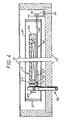
- each support comprises two high strength steel rods 65 in parallel. Both rods can be seen in Figures 2 and 3. If a single wire having sufficient strength is available it can alternatively be used.
- the rods are brazed on one end into a bar 67 which mounts to the magnet cartridge end ring 23 by means of a threaded stud with a shoulder 71. The stud is held in place with a roll pin 73.
- the bar and stud attachment to the cartridge are designed to have a minimum thickness radially in order to fit within the annular gap between the cartridge and the thermal shield.
- the other end of the steel rods are brazed into a threaded stud 75.
- This stud is bolted by nut 77 to a bracket 81 which is mounted to the vacuum vessel.
- the bracket allows the radial position of the stud to be adjusted, if necessary.
- the threaded stud is sufficiently long to permit the axial positioning of the cartridge within the vacuum vessel.
- the rods are prevented from thermally shorting to either the cartridge or the shield along the midlength by five equally spaced thermal standoffs 83 made of 0.010 inch G-10. The standoffs insure that the rods are not directly contacting either surface, and conduct only minute amounts of heat from the shield or to the cartridge.
- Wires provide an inexpensive axial support. Having separate radial and axial magnetic cartridge supports simplify assembly and adjustment. Long thin wires minimize the heat load and do not require thermal stationing to the thermal shield.
- the magnet cartridge axial supports are mounted in pairs with a pair diametrically opposite the first pair shown in Figures 5 and 6. Each axial support prevents axial motion in one axial direction. The pair prevents axial motion in either direction.
- Rotation about the vertical axis of the magnet cartridge is prevented by the radial struts and axial cables. Rotation about the radial direction lying in the horizontal plane of the magnet cartridge is prevented by the lateral struts. Rotation about the axially extending axis is prevented by the vertical and lateral radial struts.
- Thermal shield radial bumpers 85 shown in Figure 2 are described in copending application Serial No. 07/215,111, entitled “Low Thermal Conductance Support for a Radiation Shield in a MR Magnet", are used to support the thermal shield from the magnet cartridge.
- Application Serial No. 07/215,111 (EP-A-0350263) (RD-18898), entitled “Low Thermal Conductance Support for a Radiation Shield in a MR Magnet” is hereby incorporated by reference.
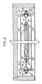
- Two of the four thermal shield axial supports 87 are shown in Figure 6.
- a single strand of wire 91 is brazed into threaded studs 93 and 95 on each end.
- Stud 95 is threaded into a tapped hole in ring 23 on the end of the magnet cartridge.
- Flats 97 are machined on the stud prior to brazing in order to facilitate the insertion and removal of the stud.
- Stud 93 extends through a clearance hole in the end flange of the thermal shield 21. Belleville spring washers 101 are compressed against the shield by a nut 103.
- Stud 93 has machined flats 104 to facilitate the tightening of the nut without twisting the wire.
- a collar 105 between the stud 93 and the stack of spring washers 101 aligns the washers and prevents contact with the stud threads.
- Stud 93 is of sufficient length permit adjustability of the axial position of the shield and to accommodate dimensional tolerance stackups.
- Two additional axial supports (not shown) are used on either end of the magnet cartridge, mounted 180° apart on the end flanges.
- the Belleville washers 101 Prior to cool down of the magnet cartridge 17 the Belleville washers 101 are compressed. As the shield 21 and magnet cartridge 17 cool down, the shield contracts axially with respect to the magnet cartridge, thus relaxing the washer stacked compression. The wire tension relaxes from the maximum pretension to a nominal tension at operating temperature. Wires provide an inexpensive axial support. Having separate radial and axial shield supports simplify initial adjustments.
Landscapes
- Physics & Mathematics (AREA)
- Electromagnetism (AREA)
- Condensed Matter Physics & Semiconductors (AREA)
- General Physics & Mathematics (AREA)
- Magnetic Resonance Imaging Apparatus (AREA)
- Containers, Films, And Cooling For Superconductive Devices (AREA)
- Particle Accelerators (AREA)
Applications Claiming Priority (2)
| Application Number | Priority Date | Filing Date | Title |
|---|---|---|---|
| US505630 | 1990-04-06 | ||
| US07/505,630 US5083105A (en) | 1990-04-06 | 1990-04-06 | Axial support system for a mr magnet |
Publications (2)
| Publication Number | Publication Date |
|---|---|
| EP0452046A2 true EP0452046A2 (fr) | 1991-10-16 |
| EP0452046A3 EP0452046A3 (en) | 1992-03-18 |
Family
ID=24011154
Family Applications (1)
| Application Number | Title | Priority Date | Filing Date |
|---|---|---|---|
| EP19910303013 Withdrawn EP0452046A3 (en) | 1990-04-06 | 1991-04-05 | Superconductive magnet |
Country Status (5)
| Country | Link |
|---|---|
| US (1) | US5083105A (fr) |
| EP (1) | EP0452046A3 (fr) |
| JP (1) | JPH04226005A (fr) |
| CA (1) | CA2034347A1 (fr) |
| IL (1) | IL97667A0 (fr) |
Cited By (4)
| Publication number | Priority date | Publication date | Assignee | Title |
|---|---|---|---|---|
| EP2075805A1 (fr) * | 2007-12-27 | 2009-07-01 | ASG Superconductors S.p.A. | Bobine ayant des enroulements supraconducteurs refroidis sans fluides cryogéniques |
| WO2014001035A1 (fr) * | 2012-06-26 | 2014-01-03 | Siemens Plc | Modification de champ magnétique à l'aide d'éléments de suspension |
| GB2537211A (en) * | 2015-02-09 | 2016-10-12 | Siemens Shenzhen Magnetic Resonance Ltd | Tensioning apparatus, superconducting magnet and magnetic resonance imaging device |
| WO2020200437A1 (fr) * | 2019-04-02 | 2020-10-08 | Siemens Healthcare Limited | Électroaimant pour irm avec structure de support mécanique |
Families Citing this family (14)
| Publication number | Priority date | Publication date | Assignee | Title |
|---|---|---|---|---|
| US5302928A (en) * | 1992-08-03 | 1994-04-12 | General Electric Company | Superconducting current leads for a cryogenless superconducting magnetic energy storage device |
| US5301507A (en) * | 1992-08-03 | 1994-04-12 | General Electric Company | Superconducting magnetic energy storage device |
| US5381122A (en) * | 1994-01-14 | 1995-01-10 | General Electric Company | Open MRI magnet having a support structure |
| US5410287A (en) * | 1994-04-05 | 1995-04-25 | General Electric Company | Open MRI magnet with uniform magnetic field |
| US5446433A (en) * | 1994-09-21 | 1995-08-29 | General Electric Company | Superconducting magnet having a shock-resistant support structure |
| US5941080A (en) * | 1997-04-02 | 1999-08-24 | Illinois Superconductor Corporation | Thin-walled cryostat |
| GB2449652B (en) * | 2007-05-30 | 2009-06-10 | Siemens Magnet Technology Ltd | Suspension rod tensioning arrangements |
| CN102226953B (zh) * | 2011-03-30 | 2013-01-30 | 中国科学院电工研究所 | 一种用于空间超导磁体的拉杆 |
| EP2839780A4 (fr) * | 2012-04-20 | 2015-04-29 | Mitsubishi Electric Corp | Aimant supraconducteur et procédé de réglage de celui-ci |
| JP6602716B2 (ja) * | 2016-03-30 | 2019-11-06 | ジャパンスーパーコンダクタテクノロジー株式会社 | 超電導マグネット装置 |
| JP6546115B2 (ja) * | 2016-03-30 | 2019-07-17 | ジャパンスーパーコンダクタテクノロジー株式会社 | 超電導マグネット装置 |
| TW202015621A (zh) | 2018-07-19 | 2020-05-01 | 美商超精細研究股份有限公司 | 在磁共振成像中患者定位之方法及設備 |
| US20220093299A1 (en) * | 2019-01-28 | 2022-03-24 | Siemens Healthcare Gmbh | Suspension apparatus for superconducting magnet, superconducting magnet and magnetic resonance imaging device |
| CN113199944B (zh) * | 2021-06-17 | 2022-03-15 | 西南交通大学 | 一种超导电动悬浮磁体的传力结构 |
Citations (3)
| Publication number | Priority date | Publication date | Assignee | Title |
|---|---|---|---|---|
| JPS6336503A (ja) * | 1986-07-30 | 1988-02-17 | Toshiba Corp | 極低温装置 |
| US4783628A (en) * | 1987-08-14 | 1988-11-08 | Houston Area Research Center | Unitary superconducting electromagnet |
| EP0350263A1 (fr) * | 1988-07-05 | 1990-01-10 | General Electric Company | Système de suspension de câble pour récipients cylindriques |
Family Cites Families (2)
| Publication number | Priority date | Publication date | Assignee | Title |
|---|---|---|---|---|
| GB8512804D0 (en) * | 1985-05-21 | 1985-06-26 | Oxford Instr Ltd | Cyclotrons |
| JPH0629635Y2 (ja) * | 1986-09-09 | 1994-08-10 | 古河電気工業株式会社 | 低温保持装置 |
-
1990
- 1990-04-06 US US07/505,630 patent/US5083105A/en not_active Expired - Fee Related
-
1991
- 1991-01-17 CA CA002034347A patent/CA2034347A1/fr not_active Abandoned
- 1991-03-25 IL IL97667A patent/IL97667A0/xx unknown
- 1991-04-04 JP JP3098003A patent/JPH04226005A/ja active Granted
- 1991-04-05 EP EP19910303013 patent/EP0452046A3/en not_active Withdrawn
Patent Citations (3)
| Publication number | Priority date | Publication date | Assignee | Title |
|---|---|---|---|---|
| JPS6336503A (ja) * | 1986-07-30 | 1988-02-17 | Toshiba Corp | 極低温装置 |
| US4783628A (en) * | 1987-08-14 | 1988-11-08 | Houston Area Research Center | Unitary superconducting electromagnet |
| EP0350263A1 (fr) * | 1988-07-05 | 1990-01-10 | General Electric Company | Système de suspension de câble pour récipients cylindriques |
Non-Patent Citations (1)
| Title |
|---|
| PATENT ABSTRACTS OF JAPAN, vol. 12, no. 246 (E-632)[3093] 12 July 1988; & JP-A-63 036 503 (TOSHIBA) 17 February 1988 * |
Cited By (9)
| Publication number | Priority date | Publication date | Assignee | Title |
|---|---|---|---|---|
| EP2075805A1 (fr) * | 2007-12-27 | 2009-07-01 | ASG Superconductors S.p.A. | Bobine ayant des enroulements supraconducteurs refroidis sans fluides cryogéniques |
| US8022798B2 (en) | 2007-12-27 | 2011-09-20 | ASG Superconductors S.p.A | Coil with superconductive windings cooled without cryogenic fluids |
| US8841980B2 (en) | 2007-12-27 | 2014-09-23 | Asg Superconductors S.P.A. | Coil with superconductive windings cooled without cryogenic fluids |
| WO2014001035A1 (fr) * | 2012-06-26 | 2014-01-03 | Siemens Plc | Modification de champ magnétique à l'aide d'éléments de suspension |
| GB2537211A (en) * | 2015-02-09 | 2016-10-12 | Siemens Shenzhen Magnetic Resonance Ltd | Tensioning apparatus, superconducting magnet and magnetic resonance imaging device |
| GB2537211B (en) * | 2015-02-09 | 2017-09-13 | Siemens Shenzhen Magnetic Resonance Ltd | Tensioning apparatus, superconducting magnet and magnetic resonance imaging device |
| WO2020200437A1 (fr) * | 2019-04-02 | 2020-10-08 | Siemens Healthcare Limited | Électroaimant pour irm avec structure de support mécanique |
| CN113646654A (zh) * | 2019-04-02 | 2021-11-12 | 西门子医疗有限公司 | 用于磁共振成像的具有机械支撑结构的电磁体 |
| US11675035B2 (en) | 2019-04-02 | 2023-06-13 | Siemens Healthcare Limited | Electromagnet and assembly |
Also Published As
| Publication number | Publication date |
|---|---|
| CA2034347A1 (fr) | 1991-10-07 |
| US5083105A (en) | 1992-01-21 |
| JPH0559565B2 (fr) | 1993-08-31 |
| JPH04226005A (ja) | 1992-08-14 |
| EP0452046A3 (en) | 1992-03-18 |
| IL97667A0 (en) | 1992-06-21 |
Similar Documents
| Publication | Publication Date | Title |
|---|---|---|
| US5083105A (en) | Axial support system for a mr magnet | |
| EP0450972B1 (fr) | Aimant supraconducteur | |
| US4986078A (en) | Refrigerated MR magnet support system | |
| EP0350262B1 (fr) | Support d'un écran de radiation dans un aimant à résonance magnétique | |
| US4924198A (en) | Superconductive magnetic resonance magnet without cryogens | |
| US4848103A (en) | Radial cryostat suspension system | |
| US4721934A (en) | Axial strap suspension system for a magnetic resonance magnet | |
| EP0350263B1 (fr) | Système de suspension de câble pour récipients cylindriques | |
| US5237300A (en) | Support structure for actively shielded superconducting magnets | |
| US4771256A (en) | Integral shield for mr magnet | |
| EP0450971B1 (fr) | Aimant supraconducteur | |
| US5381122A (en) | Open MRI magnet having a support structure | |
| GB2441795A (en) | Tubular support system for a superconducting magnet | |
| EP0284875B1 (fr) | Système de suspension pour un cryostat à résonance magnétique | |
| US4800354A (en) | Superconducting magnetic resonance magnet and method of making same | |
| JPH0272605A (ja) | クエンチ保護超導電磁石コイル | |
| EP0284874A1 (fr) | Point d'insertion thermique pour l'interconnexion d'un cryorefroidisseur avec un cryostat pour la génération d'image par résonance magnétique nucléaire | |
| JPH012635A (ja) | 磁気共鳴用極低温槽 |
Legal Events
| Date | Code | Title | Description |
|---|---|---|---|
| PUAI | Public reference made under article 153(3) epc to a published international application that has entered the european phase |
Free format text: ORIGINAL CODE: 0009012 |
|
| AK | Designated contracting states |
Kind code of ref document: A2 Designated state(s): DE FR GB NL |
|
| PUAL | Search report despatched |
Free format text: ORIGINAL CODE: 0009013 |
|
| AK | Designated contracting states |
Kind code of ref document: A3 Designated state(s): DE FR GB NL |
|
| 17P | Request for examination filed |
Effective date: 19920824 |
|
| 17Q | First examination report despatched |
Effective date: 19940704 |
|
| STAA | Information on the status of an ep patent application or granted ep patent |
Free format text: STATUS: THE APPLICATION IS DEEMED TO BE WITHDRAWN |
|
| 18D | Application deemed to be withdrawn |
Effective date: 19951105 |