EP0451728B1 - Spot-type disc brake for motor vehicles - Google Patents
Spot-type disc brake for motor vehicles Download PDFInfo
- Publication number
- EP0451728B1 EP0451728B1 EP91105434A EP91105434A EP0451728B1 EP 0451728 B1 EP0451728 B1 EP 0451728B1 EP 91105434 A EP91105434 A EP 91105434A EP 91105434 A EP91105434 A EP 91105434A EP 0451728 B1 EP0451728 B1 EP 0451728B1
- Authority
- EP
- European Patent Office
- Prior art keywords
- brake
- disc
- pair
- spot
- brake disc
- Prior art date
- Legal status (The legal status is an assumption and is not a legal conclusion. Google has not performed a legal analysis and makes no representation as to the accuracy of the status listed.)
- Expired - Lifetime
Links
Images

Classifications
-
- F—MECHANICAL ENGINEERING; LIGHTING; HEATING; WEAPONS; BLASTING
- F16—ENGINEERING ELEMENTS AND UNITS; GENERAL MEASURES FOR PRODUCING AND MAINTAINING EFFECTIVE FUNCTIONING OF MACHINES OR INSTALLATIONS; THERMAL INSULATION IN GENERAL
- F16D—COUPLINGS FOR TRANSMITTING ROTATION; CLUTCHES; BRAKES
- F16D55/00—Brakes with substantially-radial braking surfaces pressed together in axial direction, e.g. disc brakes
- F16D55/02—Brakes with substantially-radial braking surfaces pressed together in axial direction, e.g. disc brakes with axially-movable discs or pads pressed against axially-located rotating members
- F16D55/22—Brakes with substantially-radial braking surfaces pressed together in axial direction, e.g. disc brakes with axially-movable discs or pads pressed against axially-located rotating members by clamping an axially-located rotating disc between movable braking members, e.g. movable brake discs or brake pads
- F16D55/224—Brakes with substantially-radial braking surfaces pressed together in axial direction, e.g. disc brakes with axially-movable discs or pads pressed against axially-located rotating members by clamping an axially-located rotating disc between movable braking members, e.g. movable brake discs or brake pads with a common actuating member for the braking members
- F16D55/225—Brakes with substantially-radial braking surfaces pressed together in axial direction, e.g. disc brakes with axially-movable discs or pads pressed against axially-located rotating members by clamping an axially-located rotating disc between movable braking members, e.g. movable brake discs or brake pads with a common actuating member for the braking members the braking members being brake pads
- F16D55/226—Brakes with substantially-radial braking surfaces pressed together in axial direction, e.g. disc brakes with axially-movable discs or pads pressed against axially-located rotating members by clamping an axially-located rotating disc between movable braking members, e.g. movable brake discs or brake pads with a common actuating member for the braking members the braking members being brake pads in which the common actuating member is moved axially, e.g. floating caliper disc brakes
- F16D55/2265—Brakes with substantially-radial braking surfaces pressed together in axial direction, e.g. disc brakes with axially-movable discs or pads pressed against axially-located rotating members by clamping an axially-located rotating disc between movable braking members, e.g. movable brake discs or brake pads with a common actuating member for the braking members the braking members being brake pads in which the common actuating member is moved axially, e.g. floating caliper disc brakes the axial movement being guided by one or more pins engaging bores in the brake support or the brake housing
- F16D55/22655—Constructional details of guide pins
-
- F—MECHANICAL ENGINEERING; LIGHTING; HEATING; WEAPONS; BLASTING
- F16—ENGINEERING ELEMENTS AND UNITS; GENERAL MEASURES FOR PRODUCING AND MAINTAINING EFFECTIVE FUNCTIONING OF MACHINES OR INSTALLATIONS; THERMAL INSULATION IN GENERAL
- F16D—COUPLINGS FOR TRANSMITTING ROTATION; CLUTCHES; BRAKES
- F16D55/00—Brakes with substantially-radial braking surfaces pressed together in axial direction, e.g. disc brakes
- F16D55/02—Brakes with substantially-radial braking surfaces pressed together in axial direction, e.g. disc brakes with axially-movable discs or pads pressed against axially-located rotating members
- F16D55/22—Brakes with substantially-radial braking surfaces pressed together in axial direction, e.g. disc brakes with axially-movable discs or pads pressed against axially-located rotating members by clamping an axially-located rotating disc between movable braking members, e.g. movable brake discs or brake pads
- F16D55/224—Brakes with substantially-radial braking surfaces pressed together in axial direction, e.g. disc brakes with axially-movable discs or pads pressed against axially-located rotating members by clamping an axially-located rotating disc between movable braking members, e.g. movable brake discs or brake pads with a common actuating member for the braking members
- F16D55/225—Brakes with substantially-radial braking surfaces pressed together in axial direction, e.g. disc brakes with axially-movable discs or pads pressed against axially-located rotating members by clamping an axially-located rotating disc between movable braking members, e.g. movable brake discs or brake pads with a common actuating member for the braking members the braking members being brake pads
- F16D55/226—Brakes with substantially-radial braking surfaces pressed together in axial direction, e.g. disc brakes with axially-movable discs or pads pressed against axially-located rotating members by clamping an axially-located rotating disc between movable braking members, e.g. movable brake discs or brake pads with a common actuating member for the braking members the braking members being brake pads in which the common actuating member is moved axially, e.g. floating caliper disc brakes
- F16D55/2262—Brakes with substantially-radial braking surfaces pressed together in axial direction, e.g. disc brakes with axially-movable discs or pads pressed against axially-located rotating members by clamping an axially-located rotating disc between movable braking members, e.g. movable brake discs or brake pads with a common actuating member for the braking members the braking members being brake pads in which the common actuating member is moved axially, e.g. floating caliper disc brakes the axial movement being guided by open sliding surfaces, e.g. grooves
-
- F—MECHANICAL ENGINEERING; LIGHTING; HEATING; WEAPONS; BLASTING
- F16—ENGINEERING ELEMENTS AND UNITS; GENERAL MEASURES FOR PRODUCING AND MAINTAINING EFFECTIVE FUNCTIONING OF MACHINES OR INSTALLATIONS; THERMAL INSULATION IN GENERAL
- F16D—COUPLINGS FOR TRANSMITTING ROTATION; CLUTCHES; BRAKES
- F16D55/00—Brakes with substantially-radial braking surfaces pressed together in axial direction, e.g. disc brakes
- F16D55/02—Brakes with substantially-radial braking surfaces pressed together in axial direction, e.g. disc brakes with axially-movable discs or pads pressed against axially-located rotating members
- F16D55/22—Brakes with substantially-radial braking surfaces pressed together in axial direction, e.g. disc brakes with axially-movable discs or pads pressed against axially-located rotating members by clamping an axially-located rotating disc between movable braking members, e.g. movable brake discs or brake pads
- F16D55/224—Brakes with substantially-radial braking surfaces pressed together in axial direction, e.g. disc brakes with axially-movable discs or pads pressed against axially-located rotating members by clamping an axially-located rotating disc between movable braking members, e.g. movable brake discs or brake pads with a common actuating member for the braking members
- F16D55/225—Brakes with substantially-radial braking surfaces pressed together in axial direction, e.g. disc brakes with axially-movable discs or pads pressed against axially-located rotating members by clamping an axially-located rotating disc between movable braking members, e.g. movable brake discs or brake pads with a common actuating member for the braking members the braking members being brake pads
- F16D55/226—Brakes with substantially-radial braking surfaces pressed together in axial direction, e.g. disc brakes with axially-movable discs or pads pressed against axially-located rotating members by clamping an axially-located rotating disc between movable braking members, e.g. movable brake discs or brake pads with a common actuating member for the braking members the braking members being brake pads in which the common actuating member is moved axially, e.g. floating caliper disc brakes
- F16D55/2265—Brakes with substantially-radial braking surfaces pressed together in axial direction, e.g. disc brakes with axially-movable discs or pads pressed against axially-located rotating members by clamping an axially-located rotating disc between movable braking members, e.g. movable brake discs or brake pads with a common actuating member for the braking members the braking members being brake pads in which the common actuating member is moved axially, e.g. floating caliper disc brakes the axial movement being guided by one or more pins engaging bores in the brake support or the brake housing
- F16D55/227—Brakes with substantially-radial braking surfaces pressed together in axial direction, e.g. disc brakes with axially-movable discs or pads pressed against axially-located rotating members by clamping an axially-located rotating disc between movable braking members, e.g. movable brake discs or brake pads with a common actuating member for the braking members the braking members being brake pads in which the common actuating member is moved axially, e.g. floating caliper disc brakes the axial movement being guided by one or more pins engaging bores in the brake support or the brake housing by two or more pins
Definitions
- the guides of both pairs each have a pin which is attached to the brake carrier and engages in a groove running in the axial direction of the brake disc.
- the grooves of the first pair of guides are formed on the slide, while the grooves of the second pair of guides are formed on a part of the floating caliper that is arranged axially outside the brake disc.
- the object is achieved, based on a partial-pad disc brake of the type described in the introduction, in that the first pair of guides have two bolts which extend in the axial direction of the brake disc, engage with radial play in each of a guide bore and in this each by an annular support are centered elastic material whose axial width is not greater than the diameter of the associated bolt.
- the guides of the first pair resist any inclination of the assembly consisting of the slide, the floating caliper and the two brake shoes.
- the small axial width of the elastic ring supports will in any case prevent the carriage against resistance axial displacement increased significantly.
- the radial play of the bolts in the guide bores and the centering of the bolts by means of a narrow ring support prevent the bolts from jamming in the guide bores.
- the disc brake according to the invention is preferably further developed in that the ring supports of the first pair of guides lie at least approximately in the same plane normal to the axis of the brake disc as the overall center of gravity of that of the slide, floating caliper and the two Brake shoe formed assembly.
- inertial forces that occur on this assembly as a result of bumps in the roadway are completely transmitted to the brake carrier via the elastic ring supports, so that the guides of the second pair, which are arranged axially outside the brake disc, are completely kept free of such inertial forces.
- the ring supports of the first pair of guides are cylindrical and have an axial width that is 40 to 50% of the diameter of the associated bolt.
- the ring supports of the first pair of guides have a radial thickness that is 60 to 80% of their axial width.
- Each of the ring supports can consist of a single elastic ring which suitably complies with the dimensions mentioned above.
- at least one of the ring supports can be composed of at least two narrow rings which are arranged next to one another with axial gaps. It is assumed that the total axial width of such a ring arrangement is not greater than the diameter of the associated bolt.
- the guide bores of the first pair of guides each have a narrow section which extends from the associated elastic ring support in the direction of the brake disc and forms a contact surface for the associated bolt when a predetermined normal braking force is exceeded. This makes it possible to rule out with certainty that the elastic ring supports can be overloaded when the brakes are applied extremely hard.
- the guides and the brake shoes are arranged symmetrically with respect to a central plane containing the axis of the brake disc and the actuating device is offset from the central plane in the operating direction of rotation of the brake disc to the outlet side of the brake.
- the disc brake shown has a brake carrier 10 with a fastening part 12 which is to be fastened, for example, to a steering knuckle of a vehicle, two bridge parts 14, which are arranged at a distance in the circumferential direction of a brake disc 16 and extend over the outer edge thereof, and two legs 18, which protrude radially inwards from each of the bridge parts 14 axially outside the brake disc 16 and can be connected to one another by a conventional connecting part (not shown).
- a slide 20 is arranged, on the side facing away from the brake disc 16 a piston 22 is formed in one piece, and on the side facing the brake disc a first brake shoe 24 is fastened exchangeably.
- the brake shoe 24 has a back plate 26, which is embedded in a recess in the slide 20, and a brake pad 28.
- the brake disc 16 rotates when the associated motor vehicle travels about its axis A in the direction of arrow B in FIGS. 1 and 3, which characterizes the direction of rotation of operation.
- the left side of the brake in FIGS. 1 and 3 is the inlet side, while the right side is the outlet side.
- the brake carrier 10 as well as the slide 20 and the floating caliper 30 with the exception of the hydraulic actuating device 22, 32 are designed and arranged symmetrically with respect to a central plane M containing the axis A of the brake disk 16.
- the actuating device 22, 32 is arranged offset against the central plane M in the operating direction B towards the outlet side of the brake.
- each of the guides 42 has a bolt 44 parallel to the axis A, which is fastened with a screw 46 to a shoulder 48 of the slide 20 and engages with radial play in a guide bore 50 in a tubular, axially parallel projection 52 of the brake carrier 10.
- each of the two guide bores 50 has a narrow cylindrical section 54, which is adjacent to the associated projection 48 and the associated bolt 44 with an all-round radial play S54 from 0.1 to 0, 2 mm, preferably 0.15 mm encloses.
- the narrow section 54 is of a circular cylindrical shape through an annular groove 56 expanded section 58 separated, in which the associated bolt 44 has an equally large radial play S58, which is twice as large as the game S54.
- the ring support 60 has an axial width b, which is approximately 45% of its inner diameter and a radial thickness c of approximately 70% of the axial width b. It is of particular importance that each of the two elastic ring supports 60 is arranged at least approximately symmetrically with respect to a plane N (FIG. 3), which contains the overall center of gravity O of the assembly, which consists of the slide 20, the floating caliper 30 and the two brake shoes 24 and 40 exists.
- Both guides 42 each have a sleeve 62 which tightly connects the end of the bolt 44 fastened to the associated extension 48 to the adjacent end of the associated tubular projection 52.
- the opposite end of the guide bore 50 of each of the two guides 42 is sealed with a cover 64.
- the two guides 42 differ from one another in that the bolt 44 of the inlet-side guide shown in FIG. 4 is hollow and completely penetrated by the associated screw 46, while the bolt 44 of the outlet-side guide shown in FIG. 5 is solid and with the associated one Screw 46 consists of one piece.
- the design of the inlet-side guide 42 shown in FIG. 4 has the advantage that the bolt 44 can be clamped offset or away from the outlet side within a radial play S44, which it has with respect to the associated screw 46, to offset tolerances balance between the two guide bores 50.
- a second pair of guides 66 are arranged on the brake carrier 10, each of which has a pin 68 normal to the central plane M.
- the pins 68 are screwed in alignment with each other in one of the radial legs 18 of the brake carrier 10 and each have a hemispherical end 70 which engages in a groove 72 parallel to the axis A of a respective guide body 74.
- the two guide bodies 74 are each fastened with a pin 76 in a bore 78 in the leg 38 of the floating saddle 30 that is normal to the central plane M.
- Each of the two guide bodies 74 is protected against contamination by an elastic sleeve 80 sealing against the associated pin 68.
- a shield 82 made of sheet metal is assigned to the sleeves 80 for protection against thermal radiation.
Description
Die Erfindung betrifft eine Teilbelag-Scheibenbremse für Kraftfahrzeuge mit
- einem Bremsträger, der einen Rand einer Bremsscheibe umgreift,
- einem Schlitten, der an einer ersten Seite der Bremsscheibe mittels eines ersten Paars Führungen in Achsrichtung der Bremsscheibe verschiebbar am Bremsträger geführt ist und ein erstes Teil einer hydraulischen Betätigungsvorrichtung trägt,
- einem Schwimmsattel, der die Bremsscheibe und den Schlitten übergreift, auf der ersten Seite der Bremsscheibe mittels eines zweiten Teils der Betätigungsvorrichtung an deren erstem Teil in Achsrichtung der Bremsscheibe verschiebbar geführt ist und an der vom Schlitten abgewandten, zweiten Seite der Bremsscheibe mittels eines zweiten Paars Führungen am Bremsträger verschiebbar geführt ist,
- einer ersten Bremsbacke, die am Schlitten befestigt ist und durch dessen Verschiebung an die erste Seite der Bremsscheibe anpreßbar ist, sowie
- einer zweiten Bremsbacke, die am Schwimmsattel befestigt ist und durch dessen Verschiebung an die zweite Seite der Bremsscheibe anpreßbar ist,
- wobei die Führungen des zweiten Paars je einen Stift aufweisen, der sich quer zur Achsrichtung der Bremsscheibe erstreckt und in eine in Achsrichtung der Bremsscheibe verlaufende Nut eingreift.
- a brake carrier that engages around an edge of a brake disc,
- a carriage, which is guided on a first side of the brake disc by means of a first pair of guides displaceable in the axial direction of the brake disc on the brake carrier and carries a first part of a hydraulic actuating device,
- a floating caliper, which engages over the brake disc and the slide, is guided on the first side of the brake disc by means of a second part of the actuating device, on the first part of which is displaceable in the axial direction of the brake disc and on the second side of the brake disc facing away from the slide by means of a second pair of guides is slidably guided on the brake carrier,
- a first brake shoe, which is attached to the carriage and can be pressed against the first side of the brake disc by its displacement, and
- a second brake shoe, which is attached to the floating caliper and can be pressed against the second side of the brake disc by its displacement,
- wherein the guides of the second pair each have a pin which extends transversely to the axial direction of the brake disc and engages in a groove running in the axial direction of the brake disc.
Bei einer bekannten Teilbelag-Scheibenbremse dieser Gattung (EP-A 0229618) weisen die Führungen beider Paare je einen Stift auf, der am Bremsträger befestigt ist und in eine in Achsrichtung der Bremsscheibe verlaufende Nut eingreift. Die Nuten des ersten Paars Führungen sind am Schlitten ausgebildet, während die Nuten des zweiten Paars Führungen an einem axial außerhalb der Bremsscheibe angeordneten Teil des Schwimmsattels ausgebildet sind. Diese Anordnung der Stifte am Bremsträger hat den Vorteil, daß die beim Bremsen an den Bremsbacken auftretenden Bremskräfte in bezug auf den Bremsträger immer die gleichen, vom Verschleißzustand der Bremsbacken unabhängigen Hebelarme haben. Die beim Bremsen auftretenden Momente, die bestrebt sind, den Schlitten und den Schwimmsattel zu verkanten und den Bremsträger zu verwinden, sind deshalb bei gegebener Betätigungskraft konstant und lassen sich durch Einstellen eines bestimmten Spiels zwischen den Stiften und den zugehörigen Nuten derart berücksichtigen, daß Schlitten und Schwimmsattel unter allen Umständen leicht verschiebbar sind. Dabei muß allerdings in Kauf genommen werden, daß bei schneller Fahrt über Fahrbahnen mit starken Unebenheiten Klappergeräusche auftreten können, die durch das Führungsspiel bedingt sind.In a known partial-pad disc brake of this type (EP-A 0229618), the guides of both pairs each have a pin which is attached to the brake carrier and engages in a groove running in the axial direction of the brake disc. The grooves of the first pair of guides are formed on the slide, while the grooves of the second pair of guides are formed on a part of the floating caliper that is arranged axially outside the brake disc. This arrangement of the pins on the brake carrier has the advantage that the braking forces which occur when braking on the brake shoes always have the same lever arms with respect to the brake carrier which are independent of the state of wear of the brake shoes. The moments occurring during braking, which tend to tilt the sled and the floating caliper and twist the brake carrier, are therefore constant for a given actuating force and can be taken into account by setting a certain play between the pins and the associated grooves in such a way that the sled and Floating saddles are easy to move under all circumstances. However, it must be accepted that rattling noises may occur when driving fast over road surfaces with strong bumps, which are caused by the lead play.
Der Erfindung liegt die Aufgabe zugrunde, solchen Klappergeräuschen mit einfachen, die Verschiebbarkeit der genannten Bauteile nicht nennenswert behindernden Maßnahmen zu vermindern und möglichst ganz zu vermeiden.The object of the invention is to reduce such rattling noises with simple measures which do not significantly impede the displaceability of the components mentioned and to avoid them as far as possible.
Die Aufgabe ist erfindungsgemäß ausgehend von einer Teilbelag-Scheibenbremse der eingangs beschriebenen Gattung dadurch gelöst, daß das erste Paar Führungen zwei Bolzen aufweist, die sich in Achsrichtung der Bremsscheibe erstrecken, mit radialem Spiel in je eine Führungsbohrung eingreifen und in dieser durch je eine Ringstütze aus elastischem Werkstoff zentriert sind, deren axiale Breite nicht größer als der Durchmesser des zugehörigen Bolzens ist.The object is achieved, based on a partial-pad disc brake of the type described in the introduction, in that the first pair of guides have two bolts which extend in the axial direction of the brake disc, engage with radial play in each of a guide bore and in this each by an annular support are centered elastic material whose axial width is not greater than the diameter of the associated bolt.
Die Führungen des ersten Paars liegen dem Gesamtschwerpunkt der aus dem Schlitten, dem Schwimmsattel und den beiden Bremsbacken bestehenden Baugruppe auf jeden Fall näher als die Führungen des zweiten Paars. Deshalb werden Massenträgheitskräfte, die an dieser Baugruppe beim Überfahren von Fahrbahnunebenheiten auftreten, zum bei weitem überwiegenden Teil, wenn nicht ausschließlich, über die Führungen des ersten Paars auf den Bremsträger übertragen. Diese Führungen sind dank der elastischen Ringstützen spielfrei, so daß dort unter normalen Umständen kein Klappergeräusch auftreten kann. Zwischen den Stiften und Nuten der Führungen des zweiten Paars finden bei Erschütterungen höchstens geringfügige Relativbewegungen statt, und wenn dabei die Stifte überhaupt an die Wände der zugehörigen Nut anstoßen, dann geschieht dies mit so geringer Kraft, daß dadurch normalerweise kein hörbares Geräusch erzeugt wird.The guides of the first pair are in any case closer to the center of gravity of the assembly consisting of the sled, the floating caliper and the two brake shoes than the guides of the second pair. Therefore, inertia forces that occur on this assembly when driving over bumps on the road are largely, if not exclusively, transmitted to the brake carrier via the guides of the first pair. Thanks to the elastic ring supports, these guides are free of play, so that under normal circumstances no rattling noise can occur. In the event of vibrations, there are at most only slight relative movements between the pins and grooves of the guides of the second pair, and if the pins hit the walls of the associated groove at all, then this occurs with so little force that it normally does not produce any audible noise.
Bei der erfindungsgemäßen Bremse widersetzen sich die Führungen des ersten Paars jeglicher Schrägstellung der aus dem Schlitten, dem Schwimmsattel und den beiden Bremsbacken bestehenden Baugruppe. Sollte aber bei besonders kräftigem Bremsen doch eine geringfügige Schrägstellung dieser Baugruppe vorkommen, dann wird durch die geringe axiale Breite der elastischen Ringstützen jedenfalls vermieden, daß sich der Widerstand des Schlittens gegen axiale Verschiebung nennenswert erhöht. Das radiale Spiel der Bolzen in den Führungsbohrungen und die Zentrierung der Bolzen durch je eine schmale Ringstütze verhindern nämlich, daß die Bolzen sich in den Führungsbohrungen verkanten können.In the brake according to the invention, the guides of the first pair resist any inclination of the assembly consisting of the slide, the floating caliper and the two brake shoes. However, should there be a slight inclination of this assembly when the brakes are particularly strong, the small axial width of the elastic ring supports will in any case prevent the carriage against resistance axial displacement increased significantly. The radial play of the bolts in the guide bores and the centering of the bolts by means of a narrow ring support prevent the bolts from jamming in the guide bores.
Es sind zwar Teilbelag-Scheibenbremsen bekannt (DE-A 1948866 und US-A 3374866), bei denen an einem Bremsträger achsparallele Bolzen ausgebildet sind, die sich mit radialem Spiel durch Führungsbohrungen in einem Schwimmsattel erstrecken und in diesen durch elastische Ringe zentriert sind. Die Ringe sind jedoch paarweise in einem solchen Abstand voneinander angeordnet, daß die axiale Breite jeder von einem solchen Paar Ringe gebildeten Ringstütze merklich größer ist als der Durchmesser des zugehörigen Bolzens. Entsprechendes gilt auch für eine andere bekannte Teilbelag-Scheibenbremse (DE-A 2211429), bei der am Schwimmsattel achsparallele Bolzen befestigt sind, die sich mit radialem Spiel durch je eine Führungsbohrung im Bremsträger erstrecken und in dieser durch je eine elastische Ringstütze zentriert sind. All diese bekannten Teilbelag-Scheibenbremsen haben im übrigen kein Bauteil, das mit einem Schlitten einer Scheibenbremse der eingangs beschriebenen Gattung vergleichbar wäre; auch fehlt ihnen das Merkmal, daß der Schwimmsattel axial außerhalb der Bremsscheibe durch ein zweites Paar Führungen mit je einem sich quer zur Achsrichtung der Bremsscheibe erstreckenden Stift und je einer in Achsrichtung der Bremsscheibe verlaufenden Nut geführt ist.There are partial pad disc brakes known (DE-A 1948866 and US-A 3374866), in which axially parallel bolts are formed on a brake carrier, which extend with radial play through guide holes in a floating caliper and are centered therein by elastic rings. However, the rings are arranged in pairs at such a distance from one another that the axial width of each ring support formed by such a pair of rings is significantly larger than the diameter of the associated bolt. The same also applies to another known partial-pad disc brake (DE-A 2211429), in which axially parallel bolts are attached to the floating caliper, which extend with radial play through a guide bore in the brake carrier and are centered in each by an elastic ring support. All these known partial-pad disc brakes have no other component that would be comparable to a slide of a disc brake of the type described above; They also lack the feature that the floating caliper is guided axially outside the brake disc by a second pair of guides, each with a pin extending transversely to the axial direction of the brake disc and a groove running in the axial direction of the brake disc.
Die erfindungsgemäße Scheibenbremse ist vorzugsweise dadurch weitergebildet, daß die Ringstützen des ersten Paars Führungen mindestens annähernd in derselben zur Achse der Bremsscheibe normalen Ebene liegen wie der Gesamtschwerpunkt der von dem Schlitten, Schwimmsattel und den beiden Bremsbacken gebildeten Baugruppe. Bei dieser Weiterbildung werden Massenträgheitskräfte, die an dieser Baugruppe infolge von Fahrbahnunebenheiten auftreten, vollständig über die elastischen Ringstützen auf den Bremsträger übertragen, so daß die axial außerhalb der Bremsscheibe angeordneten Führungen des zweiten Paars von solchen Massenträgheitskräften vollständig freigehalten werden.The disc brake according to the invention is preferably further developed in that the ring supports of the first pair of guides lie at least approximately in the same plane normal to the axis of the brake disc as the overall center of gravity of that of the slide, floating caliper and the two Brake shoe formed assembly. In this development, inertial forces that occur on this assembly as a result of bumps in the roadway are completely transmitted to the brake carrier via the elastic ring supports, so that the guides of the second pair, which are arranged axially outside the brake disc, are completely kept free of such inertial forces.
Erfindungsgemäß ist es ferner vorteilhaft, wenn die Bolzen des ersten Paars Führungen am Schlitten befestigt sind und die zugehörigen Führungsbohrungen am Bremsträger ausgebildet sind und Ringnuten aufweisen, in denen die Ringstützen aufgenommen sind. Dadurch bleibt der Vorteil der bekannten Scheibenbremse der eingangs beschriebenen Gattung erhalten, daß jeder der an den beiden Bremsbacken auftretenden Bremskräfte in bezug auf die zugehörigen Führungen unabhängig vom Abnutzungszustand der betreffenden Bremsbacke stets den gleichen Hebelarm hat.According to the invention, it is also advantageous if the bolts of the first pair of guides are fastened to the slide and the associated guide bores are formed on the brake carrier and have annular grooves in which the ring supports are received. This maintains the advantage of the known disc brake of the type described in the introduction that each of the braking forces occurring on the two brake shoes always has the same lever arm with respect to the associated guides, regardless of the state of wear of the brake shoe in question.
Es ist ferner vorteilhaft, wenn die Ringstützen des ersten Paars Führungen zylindrisch sind und eine axiale Breite haben, die 40 bis 50% des Durchmessers des zugehörigen Bolzens beträgt.It is also advantageous if the ring supports of the first pair of guides are cylindrical and have an axial width that is 40 to 50% of the diameter of the associated bolt.
Außerdem ist es zweckmäßig, wenn die Ringstützen des ersten Paars Führungen eine radiale Dicke haben, die 60 bis 80% ihrer axialen Breite beträgt.It is also expedient if the ring supports of the first pair of guides have a radial thickness that is 60 to 80% of their axial width.
Jede der Ringstützen kann aus einem einzigen elastischen Ring bestehen, der zweckmäßigerweise die vorstehend genannten Maßverhältnisse einhält. Es ist aber auch möglich, daß mindestens eine der Ringstützen aus mindestens zwei schmalen Ringen zusammengesetzt ist, die mit axialen Zwischenräumen nebeneinander angeordnet sind. Dabei ist vorausgesetzt, daß die axiale Gesamtbreite einer solchen Ringanordnung nicht größer als der Durchmesser des zugehörigen Bolzens ist.Each of the ring supports can consist of a single elastic ring which suitably complies with the dimensions mentioned above. However, it is also possible for at least one of the ring supports to be composed of at least two narrow rings which are arranged next to one another with axial gaps. It is assumed that the total axial width of such a ring arrangement is not greater than the diameter of the associated bolt.
Besonders vorteilhaft ist, wenn die Maße und Elastizität der Ringstützen derart gewählt sind, daß die Ringstützen bei Belastung durch Bremskräfte mindestens annähernd die gleiche Kraft-Weg-Charakteristik haben wie der Bremsträger im Bereich jeder der Führungen des zweiten Paars. Damit wird erreicht, daß die Abstützung beider Bremsbacken gegen die beim Bremsen auftretenden Umfangskräfte im wesentlichen gleiche Federkonstanten aufweisen; mit anderen Worten wird die Tatsache ausgeglichen, daß der Bremsträger sich in dem axial äußeren Bereich, in dem er über den Schwimmsattel die Bremskraft der axial äußeren Bremsbacke aufnimmt, stärker verformt als in dem axial inneren Bereich, in dem er über den Schlitten die Bremskraft der ersten Bremsbacke aufnimmt.It is particularly advantageous if the dimensions and elasticity of the ring supports are selected in such a way that the ring supports have at least approximately the same force-displacement characteristics as the brake carrier in the area of each of the guides of the second pair when subjected to braking forces. This ensures that the support of both brake shoes against the circumferential forces occurring during braking have essentially the same spring constants; in other words, the fact is compensated for that the brake carrier is deformed more in the axially outer region in which it absorbs the braking force of the axially outer brake shoe via the floating caliper than in the axially inner region in which it brakes the braking force of the takes up the first brake shoe.
Es ist außerdem zweckmäßig, wenn die Führungsbohrungen des ersten Paars Führungen je einen engen Abschnitt haben, der sich von der zugehörigen elastischen Ringstütze in Richtung zur Bremsscheibe erstreckt und bei Überschreiten einer vorbestimmten normalen Bremskraft eine Anlagefläche für den zugehörigen Bolzen bildet. Dadurch läßt sich mit Sicherheit ausschließen, daß die elastischen Ringstützen bei extrem starkem Bremsen überlastet werden können.It is also expedient if the guide bores of the first pair of guides each have a narrow section which extends from the associated elastic ring support in the direction of the brake disc and forms a contact surface for the associated bolt when a predetermined normal braking force is exceeded. This makes it possible to rule out with certainty that the elastic ring supports can be overloaded when the brakes are applied extremely hard.
Schließlich ist es vorteilhaft, wenn die Führungen sowie die Bremsbacken symmetrisch in bezug auf eine die Achse der Bremsscheibe enthaltende Mittelebene angeordnet sind und die Betätigungsvorrichtung gegen die Mittelebene in der Betriebsdrehrichtung der Bremsscheibe zur Auslaufseite der Bremse versetzt ist.Finally, it is advantageous if the guides and the brake shoes are arranged symmetrically with respect to a central plane containing the axis of the brake disc and the actuating device is offset from the central plane in the operating direction of rotation of the brake disc to the outlet side of the brake.
Ein Ausführungsbeispiel der Erfindung wird im folgenden anhand schematischer Zeichnungen mit weiteren Einzelheiten erläutert. Es zeigen:
- Fig. 1
- eine Seitenansicht einer Teilbelag-Scheibenbremse,
- Fig. 2
- die zugehörige Vorderansicht in Richtung des Pfeils II in Fig. 1,
- Fig. 3
- den Schnitt III-III in Fig. 1,
- Fig. 4
- den vergrößerten Ausschnitt IV in Fig. 3 und
- Fig. 5
- den vergrößerten Ausschnitt V in Fig. 3.
- Fig. 1
- a side view of a partial lining disc brake,
- Fig. 2
- the associated front view in the direction of arrow II in Fig. 1,
- Fig. 3
- the section III-III in Fig. 1,
- Fig. 4
- the enlarged section IV in Fig. 3 and
- Fig. 5
- the enlarged section V in Fig. 3rd
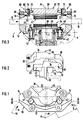
Die dargestellte Scheibenbremse hat einen Bremsträger 10 mit einem Befestigungsteil 12, das beispielsweise an einem Achsschenkel eines Fahrzeugs zu befestigen ist, zwei Brückenteilen 14, die mit Abstand in Umfangsrichtung einer Bremsscheibe 16 angeordnet sind und sich über deren äußeren Rand hinwegerstrecken, sowie zwei Schenkeln 18, die von je einem der Brückenteile 14 aus axial außerhalb der Bremsscheibe 16 radial nach innen ragen und durch ein nicht dargestelltes, übliches Verbindungsteil miteinander verbunden sein können.The disc brake shown has a
An der axial inneren Seite des Bremsträgers 10 ist ein Schlitten 20 angeordnet, an dessen von der Bremsscheibe 16 abgewandter Seite ein Kolben 22 einstückig ausgebildet ist, und an dessen der Bremsscheibe zugewandter Seite eine erste Bremsbacke 24 auswechselbar befestigt ist. Die Bremsbacke 24 hat eine Rückenplatte 26, die in eine Aussparung des Schlittens 20 eingelassen ist, sowie einen Bremsbelag 28.On the axially inner side of the
Zwischen den beiden Brückenteilen 14 des Bremsträgers 10 ist ein Schwimmsattel 30 angeordnet, der die Bremsscheibe 16 und den Schlitten 20 übergreift. Der Schwimmsattel 30 hat einen hydraulischen Zylinder 32, der mit einem axial inneren Sattelteil 34 einstückig ausgebildet ist und zusammen mit dem Kolben 22 eine hydraulische Betätigungsvorrichtung bildet. Der Schwimmsattel 30 hat ferner ein mit dem axial inneren Sattelteil 34 fest verschraubtes axial äußeres Sattelteil 36, das sich über den äußeren Rand der Bremsscheibe 16 hinwegerstreckt und axial außerhalb von dieser einen radial nach innen ragenden Schenkel 38 aufweist, an dem eine zweite Bremsbacke 40 befestigt ist.A floating
Die Bremsscheibe 16 dreht sich bei Vorwärtsfahrt des zugehörigen Kraftfahrzeugs um ihre Achse A im Sinne des Pfeils B in Fig. 1 und 3, der die Betriebsdrehrichtung kennzeichnet. Dabei ist die in Fig. 1 und 3 linke Seite der Bremse die Einlaufseite, während die rechte Seite die Auslaufseite ist. Der Bremsträger 10 sowie der Schlitten 20 und der Schwimmsattel 30 mit Ausnahme der hydraulischen Betätigungsvorrichtung 22, 32 sind symmetrisch in bezug auf eine die Achse A der Bremsscheibe 16 enthaltende Mittelebene M gestaltet und angeordnet. Die Betätigungsvorrichtung 22, 32 ist gegen die Mittelebene M in der Betriebsdrehrichtung B zur Auslaufseite der Bremse hin versetzt angeordnet.The
Der Schlitten 20 ist am Bremsträger 10 mit einem ersten Paar Führungen 42 geführt, die symmetrisch zur Mittelebene M angeordnet sind. Jede der Führungen 42 hat einen zur Achse A parallelen Bolzen 44, der mit einer Schraube 46 an einem Ansatz 48 des Schlittens 20 befestigt ist und mit radialem Spiel in eine Führungsbohrung 50 in einem rohrförmigen achsparallelen Vorsprung 52 des Bremsträgers 10 eingreift. Jede der beiden Führungsbohrungen 50 hat, wie besonders aus Fig. 4 und 5 ersichtlich ist, einen engen zylindrischen Abschnitt 54, der dem zugehörigen Ansatz 48 benachbart ist und den zugehörigen Bolzen 44 mit einem rundum gleichgroßen radialen Spiel S54 von 0,1 bis 0,2 mm, vorzugsweise 0,15 mm umschließt. Der enge Abschnitt 54 ist durch eine Ringnut 56 von einem ebenfalls kreiszylindrischen erweiterten Abschnitt 58 getrennt, in dem der zugehörige Bolzen 44 ein allseits gleichgroßes radiales Spiel S58 hat, das doppelt so groß ist wie das Spiel S54.The carriage 20 is guided on the
In der Ringnut 56 ist eine elastische Ringstütze 60 in Gestalt eines zylindrischen Rings 60 aufgenommen, der aus Gummi oder einem Elastomeren besteht, und in dem der zugehörige Bolzen 44 spielfrei geführt ist. Die Ringstütze 60 hat eine axiale Breite b, die ungefähr 45% ihres Innendurchmessers beträgt und eine radiale Dicke c von etwa 70% der axialen Breite b. Von besonderer Bedeutung ist, daß jede der beiden elastischen Ringstützen 60 mindestens annähernd symmetrisch in bezug auf eine Ebene N (Fig. 3) angeordnet ist, die den Gesamtschwerpunkt O der Baugruppe enthält, die aus dem Schlitten 20, dem Schwimmsattel 30 und den beiden Bremsbacken 24 und 40 besteht.An
Beide Führungen 42 haben je eine Manschette 62, die das am zugehörigen Ansatz 48 befestigte Ende des Bolzens 44 mit dem benachbarten Ende des zugehörigen rohrförmigen Vorsprungs 52 dicht verbindet. Das entgegengesetzte Ende der Führungsbohrung 50 jeder der beiden Führungen 42 ist mit einem Deckel 64 dicht verschlossen.Both guides 42 each have a
Die beiden Führungen 42 unterscheiden sich voneinander dadurch, daß der Bolzen 44 der in Fig. 4 dargestellten einlaufseitigen Führung hohl und von der zugehörigen Schraube 46 vollständig durchsetzt ist, während der in Fig. 5 dargestellte Bolzen 44 der auslaufseitigen Führung massiv ist und mit der zugehörigen Schraube 46 aus einem Stück besteht. Die in Fig. 4 abgebildete Gestaltung der einlaufseitigen Führung 42 hat den Vorteil, daß der Bolzen 44 innerhalb eines radialen Spiels S44, das er gegenüber der zugehörigen Schraube 46 hat, zur Auslaufseite hin oder von dieser weg versetzt festgeklemmt werden kann, um Abstandstoleranzen zwischen den beiden Führungsbohrungen 50 auszugleichen.The two guides 42 differ from one another in that the
Axial außerhalb der Bremsscheibe 16 ist am Bremsträger 10 ein zweites Paar Führungen 66 angeordnet, die je einen zur Mittelebene M normalen Stift 68 aufweisen. Die Stifte 68 sind miteinander fluchtend in je einen der radialen Schenkel 18 des Bremsträgers 10 eingeschraubt und haben je ein halbkugelförmiges Ende 70, das in eine zur Achse A parallele Nut 72 je eines Führungskörpers 74 eingreift. Die beiden Führungskörper 74 sind mit je einem Zapfen 76 in je einer zur Mittelebene M normalen Bohrung 78 im Schenkel 38 des Schwimmsattels 30 befestigt.Axially outside the
Jeder der beiden Führungskörper 74 ist durch eine gegen den zugehörigen Stift 68 abdichtende elastische Manschette 80 gegen Verschmutzung geschützt. Den Manschetten 80 ist zum Schutz gegen Wärmestrahlung je ein Schild 82 aus Blech zugeordnet.Each of the two
Claims (9)
- A spot-type disc brake for motor vehicles, comprising- a brake carrier member (10) which embraces an edge of a brake disc (16),- a slide member (20) which is guided at the carrier member (10), at a first side of the brake disc (16), by a first pair of guide means (42) so as to be displaceable in axial direction of the brake disc (16) and which carries a first part (22) of an hydraulic actuating device (22, 32),- a floating caliper (30) which straddles the brake disc (16) and the slide member (20) and which is guided at the first part (22) of the actuating device (22, 32), at the first side of the brake disc (16), by means of a second part (32) of said device so as to be displaceable in axial direction of the brake disc (16) and further guided at the second side of the brake disc (16), remote from the slide member, by means of a second pair of guide means (66) so as to be displaceable at the brake carrier member (10),- a first brake pad (24) fixed to the slide member (20) and adapted to be pressed against the first side of the brake disc (16) by displacement of the slide member, and- a second brake pad (40) fixed to the floating caliper (30) and adapted to be pressed against the second side of the brake disc (16) by displacement of the floating caliper,- the guide means (66) of the second pair each comprising a pin (68) which is oriented transversely of the axial direction of the brake disc (16) and engages in a groove (72) extending in axial direction of the brake disc (16), characterized in that the first pair of guide means (42) comprises two bolts (44) extending in axial direction of the brake disc (16), engaging with radial clearance in a guide bore (50) each and being centered in the same by an annular prop (60) each, made of elastic material, whose axial width (b) is no greater than the diameter (d) of the corresponding bolt (44).
- The spot-type disc brake as claimed in claim 1, characterized in that the annular props (60) of the first pair of guide means (42) lie at least approximately in the same plane (N) at right angles to the axis (A) of the brake disc (16) as does the overall center of gravity (O) of the assembly composed of the slide member (20), the floating caliper (30), and the two brake pads (24, 40).
- The spot-type disc brake as claimed in claim 1 or 2, characterized in that the bolts (44) of the first pair of guide means (42) are fastened to the slide member (20) and the corresponding guide bores (50) are formed in the brake carrier member (10) and include annular grooves (56) to receive the annular props (60).
- The spot-type disc brake as claimed in any one of claims 1 to 3, characterized in that the annular props (60) of the first pair of guide means (42) are cylindrical and have an axial width (b) which corresponds to from 40 to 50% of the diameter of the corresponding bolt (44).
- The spot-type disc brake as claimed in any one of claims 1 to 4, characterized in that the annular props (60) of the first pair of guide means (42) have a radial thickness (c) which corresponds to from 60 to 80% of their maximum width (b).
- The spot-type disc brake as claimed in claim 4 or 5, characterized in that at least one of the annular props (60) is composed of at least two narrow rings arranged side by side with axial spacings in between.
- The spot-type disc brake as claimed in any one of claims 1 to 6, characterized in that the annular props (60), when loaded by braking forces, have at least approximately the same force-path characteristic as the brake carrier member (10) in the area of each of the guide means (66) of the second pair.
- The spot-type disc brake as claimed in any one of claims 1 to 7, characterized in that the guide bores (50) of the first pair of guide means (42) each have a narrow section (54) extending from the respective elastic annular prop (60) in the direction toward the brake disc (16) and presenting an engagement surface for the corresponding bolt (44) when a predetermined normal braking force is exceeded.
- The spot-type disc brake as claimed in any one of claims 1 to 8, characterized in that the guide means (42, 66) as well as the brake pads (24, 40) are disposed symmetrically with respect to a center plane (M) in which lies the axis (A) of the brake disc (16), while the actuating device (22, 32) is offset with respect to the center plane (M) in the operating direction of rotation (B) of the brake disc (16) toward the trailing side of the brake.
Applications Claiming Priority (2)
| Application Number | Priority Date | Filing Date | Title |
|---|---|---|---|
| DE9003990U DE9003990U1 (en) | 1990-04-05 | 1990-04-05 | |
| DE9003990U | 1990-04-05 |
Publications (2)
| Publication Number | Publication Date |
|---|---|
| EP0451728A1 EP0451728A1 (en) | 1991-10-16 |
| EP0451728B1 true EP0451728B1 (en) | 1993-09-08 |
Family
ID=6852677
Family Applications (1)
| Application Number | Title | Priority Date | Filing Date |
|---|---|---|---|
| EP91105434A Expired - Lifetime EP0451728B1 (en) | 1990-04-05 | 1991-04-05 | Spot-type disc brake for motor vehicles |
Country Status (4)
| Country | Link |
|---|---|
| EP (1) | EP0451728B1 (en) |
| JP (1) | JPH04224322A (en) |
| DE (2) | DE9003990U1 (en) |
| ES (1) | ES2044641T3 (en) |
Cited By (1)
| Publication number | Priority date | Publication date | Assignee | Title |
|---|---|---|---|---|
| CN103883647A (en) * | 2014-04-01 | 2014-06-25 | 武汉轻工大学 | Thin-wall braking sleeve of direct drive rotary table and manufacturing method |
Families Citing this family (4)
| Publication number | Priority date | Publication date | Assignee | Title |
|---|---|---|---|---|
| DE4314719A1 (en) * | 1993-05-04 | 1994-11-10 | Knorr Bremse Ag | Air operated sliding caliper disc brake for commercial vehicles |
| JP2015155348A (en) * | 2014-02-21 | 2015-08-27 | 株式会社日立製作所 | Elevator and hoisting machine of the same |
| DE102015107128A1 (en) * | 2015-05-07 | 2016-11-10 | Knorr-Bremse Systeme für Nutzfahrzeuge GmbH | Disc brake of a commercial vehicle |
| IT201800006539A1 (en) * | 2018-06-21 | 2019-12-21 | DISC BRAKE CALIPER |
Family Cites Families (6)
| Publication number | Priority date | Publication date | Assignee | Title |
|---|---|---|---|---|
| US3374866A (en) * | 1966-10-06 | 1968-03-26 | Kelsey Hayes Co | Mounting means for a sliding caliper disk brake |
| JPS507701B1 (en) * | 1968-10-01 | 1975-03-28 | ||
| GB1382046A (en) * | 1971-03-09 | 1975-01-29 | Girling Ltd | Caliper disc brakes |
| US4334599A (en) * | 1980-08-18 | 1982-06-15 | The Bendix Corporation | Disc brake and mounting pin assembly therefor |
| DE3542388A1 (en) * | 1985-11-30 | 1987-06-04 | Teves Gmbh Alfred | PARTIAL DISC BRAKE, IN PARTICULAR FOR MOTOR VEHICLES |
| EP0229618B1 (en) * | 1986-01-17 | 1990-04-04 | LUCAS INDUSTRIES public limited company | Floating caliper spot-type disc brake |
-
1990
- 1990-04-05 DE DE9003990U patent/DE9003990U1/de not_active Expired - Lifetime
-
1991
- 1991-04-05 JP JP3073228A patent/JPH04224322A/en active Pending
- 1991-04-05 ES ES91105434T patent/ES2044641T3/en not_active Expired - Lifetime
- 1991-04-05 EP EP91105434A patent/EP0451728B1/en not_active Expired - Lifetime
- 1991-04-05 DE DE91105434T patent/DE59100355D1/en not_active Expired - Fee Related
Cited By (2)
| Publication number | Priority date | Publication date | Assignee | Title |
|---|---|---|---|---|
| CN103883647A (en) * | 2014-04-01 | 2014-06-25 | 武汉轻工大学 | Thin-wall braking sleeve of direct drive rotary table and manufacturing method |
| CN103883647B (en) * | 2014-04-01 | 2016-02-10 | 武汉轻工大学 | Directly turn platform thin-walled braking sleeve and braking method |
Also Published As
| Publication number | Publication date |
|---|---|
| EP0451728A1 (en) | 1991-10-16 |
| ES2044641T3 (en) | 1994-01-01 |
| DE9003990U1 (en) | 1991-08-01 |
| DE59100355D1 (en) | 1993-10-14 |
| JPH04224322A (en) | 1992-08-13 |
Similar Documents
| Publication | Publication Date | Title |
|---|---|---|
| DE1450130C3 (en) | Hydraulically operated partially lined disc brake | |
| DE2031249C3 (en) | Floating caliper partially lined disc brake | |
| DE1930685C3 (en) | Brake caliper guide for a floating caliper part-lined disc brake | |
| DE2631457A1 (en) | DISC BRAKE | |
| DE1625676B2 (en) | Guide for the floating caliper of a partially lined disc brake | |
| DE3340442C2 (en) | Chassis assembly for attaching wheel axles and brakes to motor vehicles | |
| DE2061673C3 (en) | Partly lined disc brake | |
| DE2340316B2 (en) | Guide for the saddle or frame of a floating caliper or floating frame part-lining disc brake, in particular for motor vehicles | |
| DE2211453C3 (en) | Guide for the caliper of a floating caliper disc brake on the brake carrier | |
| DE1206673B (en) | Pressure fluid operated partially lined disc brake | |
| DE19810685C5 (en) | disc brake | |
| EP0451728B1 (en) | Spot-type disc brake for motor vehicles | |
| DE3438209C2 (en) | Disc brake, in particular for motor vehicles | |
| EP0248024B1 (en) | Partial lining disc brake, especially for motor vehicles | |
| DE2753821C2 (en) | Disc brake | |
| DE1937555C3 (en) | Guide for the frame or saddle of a floating frame or floating saddle-partially covered disc brake | |
| EP0350867B1 (en) | Spot-type disc brake | |
| EP0242694B1 (en) | Brake pad for a disc brake | |
| DE2705788C2 (en) | Guide for the saddle of a hydraulically actuated floating-caliper partially covered disc brake for vehicles | |
| DE10260829A1 (en) | Radial mounting type disc brake for vehicle, has communication path arranged between exit side bolt attachment hole and brake pad on caliper and positioned relative to disc rotation direction | |
| DE3032513C2 (en) | ||
| DE2845936C2 (en) | ||
| EP0469310B1 (en) | Brake pad for spot-type disc brakes | |
| EP0150052B1 (en) | Spot-type disc brake for vehicles | |
| DE2807125C2 (en) | Floating-caliper partially lined disc brakes, in particular for motor vehicles |
Legal Events
| Date | Code | Title | Description |
|---|---|---|---|
| PUAI | Public reference made under article 153(3) epc to a published international application that has entered the european phase |
Free format text: ORIGINAL CODE: 0009012 |
|
| AK | Designated contracting states |
Kind code of ref document: A1 Designated state(s): DE ES FR GB IT |
|
| 17P | Request for examination filed |
Effective date: 19911009 |
|
| 17Q | First examination report despatched |
Effective date: 19930210 |
|
| GRAA | (expected) grant |
Free format text: ORIGINAL CODE: 0009210 |
|
| AK | Designated contracting states |
Kind code of ref document: B1 Designated state(s): DE ES FR GB IT |
|
| REF | Corresponds to: |
Ref document number: 59100355 Country of ref document: DE Date of ref document: 19931014 |
|
| GBT | Gb: translation of ep patent filed (gb section 77(6)(a)/1977) |
Effective date: 19930922 |
|
| ET | Fr: translation filed | ||
| ITF | It: translation for a ep patent filed |
Owner name: MODIANO & ASSOCIATI S.R |
|
| REG | Reference to a national code |
Ref country code: ES Ref legal event code: FG2A Ref document number: 2044641 Country of ref document: ES Kind code of ref document: T3 |
|
| PLBE | No opposition filed within time limit |
Free format text: ORIGINAL CODE: 0009261 |
|
| STAA | Information on the status of an ep patent application or granted ep patent |
Free format text: STATUS: NO OPPOSITION FILED WITHIN TIME LIMIT |
|
| 26N | No opposition filed | ||
| REG | Reference to a national code |
Ref country code: GB Ref legal event code: IF02 |
|
| REG | Reference to a national code |
Ref country code: GB Ref legal event code: 732E |
|
| REG | Reference to a national code |
Ref country code: GB Ref legal event code: 732E |
|
| PGFP | Annual fee paid to national office [announced via postgrant information from national office to epo] |
Ref country code: GB Payment date: 20080317 Year of fee payment: 18 |
|
| PGFP | Annual fee paid to national office [announced via postgrant information from national office to epo] |
Ref country code: DE Payment date: 20080430 Year of fee payment: 18 Ref country code: ES Payment date: 20080414 Year of fee payment: 18 |
|
| PGFP | Annual fee paid to national office [announced via postgrant information from national office to epo] |
Ref country code: IT Payment date: 20080419 Year of fee payment: 18 |
|
| PGFP | Annual fee paid to national office [announced via postgrant information from national office to epo] |
Ref country code: FR Payment date: 20080403 Year of fee payment: 18 |
|
| GBPC | Gb: european patent ceased through non-payment of renewal fee |
Effective date: 20090405 |
|
| REG | Reference to a national code |
Ref country code: FR Ref legal event code: ST Effective date: 20091231 |
|
| PG25 | Lapsed in a contracting state [announced via postgrant information from national office to epo] |
Ref country code: DE Free format text: LAPSE BECAUSE OF NON-PAYMENT OF DUE FEES Effective date: 20091103 |
|
| PG25 | Lapsed in a contracting state [announced via postgrant information from national office to epo] |
Ref country code: FR Free format text: LAPSE BECAUSE OF NON-PAYMENT OF DUE FEES Effective date: 20091222 Ref country code: GB Free format text: LAPSE BECAUSE OF NON-PAYMENT OF DUE FEES Effective date: 20090405 |
|
| REG | Reference to a national code |
Ref country code: ES Ref legal event code: FD2A Effective date: 20090406 |
|
| PG25 | Lapsed in a contracting state [announced via postgrant information from national office to epo] |
Ref country code: ES Free format text: LAPSE BECAUSE OF NON-PAYMENT OF DUE FEES Effective date: 20090406 |
|
| PG25 | Lapsed in a contracting state [announced via postgrant information from national office to epo] |
Ref country code: IT Free format text: LAPSE BECAUSE OF NON-PAYMENT OF DUE FEES Effective date: 20090405 |