EP0451505A1 - Incremental position measuring system - Google Patents
Incremental position measuring system Download PDFInfo
- Publication number
- EP0451505A1 EP0451505A1 EP91103460A EP91103460A EP0451505A1 EP 0451505 A1 EP0451505 A1 EP 0451505A1 EP 91103460 A EP91103460 A EP 91103460A EP 91103460 A EP91103460 A EP 91103460A EP 0451505 A1 EP0451505 A1 EP 0451505A1
- Authority
- EP
- European Patent Office
- Prior art keywords
- counter
- measuring system
- signals
- position measuring
- incremental position
- Prior art date
- Legal status (The legal status is an assumption and is not a legal conclusion. Google has not performed a legal analysis and makes no representation as to the accuracy of the status listed.)
- Granted
Links
Images
Classifications
-
- G—PHYSICS
- G01—MEASURING; TESTING
- G01D—MEASURING NOT SPECIALLY ADAPTED FOR A SPECIFIC VARIABLE; ARRANGEMENTS FOR MEASURING TWO OR MORE VARIABLES NOT COVERED IN A SINGLE OTHER SUBCLASS; TARIFF METERING APPARATUS; MEASURING OR TESTING NOT OTHERWISE PROVIDED FOR
- G01D5/00—Mechanical means for transferring the output of a sensing member; Means for converting the output of a sensing member to another variable where the form or nature of the sensing member does not constrain the means for converting; Transducers not specially adapted for a specific variable
- G01D5/12—Mechanical means for transferring the output of a sensing member; Means for converting the output of a sensing member to another variable where the form or nature of the sensing member does not constrain the means for converting; Transducers not specially adapted for a specific variable using electric or magnetic means
- G01D5/244—Mechanical means for transferring the output of a sensing member; Means for converting the output of a sensing member to another variable where the form or nature of the sensing member does not constrain the means for converting; Transducers not specially adapted for a specific variable using electric or magnetic means influencing characteristics of pulses or pulse trains; generating pulses or pulse trains
- G01D5/245—Mechanical means for transferring the output of a sensing member; Means for converting the output of a sensing member to another variable where the form or nature of the sensing member does not constrain the means for converting; Transducers not specially adapted for a specific variable using electric or magnetic means influencing characteristics of pulses or pulse trains; generating pulses or pulse trains using a variable number of pulses in a train
- G01D5/2451—Incremental encoders
Definitions
- the invention relates to an incremental position measuring system according to the preamble of claim 1.
- Such position measuring systems are used in particular in numerical controls for measuring the relative position of a tool with respect to a workpiece to be machined, and in coordinate measuring machines.
- a grid-like incremental measuring graduation is scanned with a scanning device and periodic analog signals are generated. Square-wave signals are formed from the periodic analog signals and are fed to an up / down counter. The counter reading indicates the relative position of the objects to be measured. If the power supply fails, the meter reading and thus the knowledge of the current one Relative position lost.
- a reference mark must be approached, the absolute position of which is known. When this reference mark is passed, the up / down counter is set to a predetermined value and the measurement must be started again.
- the invention has for its object to provide an incremental position measuring system so that it works in a fail-safe and energy-saving manner and can quickly output the absolute relative position between the objects to be measured after a failure of the main power supply.
- the advantages achieved by the invention are, in particular, that after a failure of the main power supply, the relative position is present again exactly and can be passed on to an external unit by simple means.
- the interface of the external unit can therefore be simple.
- the scanner 1 is two Analog scanning signals S1, S2 which are phase-shifted from one another by 90 ° to an evaluation device 2.
- counting signals S3, S4 are formed in a direction discriminator 3 from the two phase-shifted analog scanning signals S1, S2.
- the evaluation device 2 also contains an absolute value counter 4, to which the count signals S3, S4 are continuously fed.
- This absolute value counter 4, the direction discriminator 3 and the scanning device 1 are continuously supplied with current; this power supply can be operated, for example, in a particularly economical manner.
- the current power supply guarantees that the counter reading of the absolute value counter 4 always corresponds to the current relative position and can be output if required.
- the power supply consists of a main power supply 5 and an emergency power supply 6. Both power supplies 5 and 6 are connected to a monitoring device 7. This monitoring device 7 continuously checks the voltage level of the main power supply 5, as soon as the voltage level falls below a predetermined value, the main power supply 5 switches over to the emergency power supply 6.
- the main power supply 5 is integrated, for example, in a numerical control 8 and the emergency power supply 6 can be a battery or a storage capacitor.
- the emergency power supply 6 is also included in the numerical control 8 in the example shown.
- Normal operation means that the main power supply 5 is in operation and has a voltage level above the predetermined value.
- the monitoring device 7 detects normal operation and supplies a display signal S5 to a control logic 9.
- the control logic 9 activates a pulse generator 10 via the control signal S6, which outputs direction-dependent counting signals S7, S8 to a follow-up counter 11 as a function of the count of the absolute value counter 4.
- the counter values of the absolute value counter 4 and the follow-up counter 11 are continuously compared with one another by means of a comparator 12 and the comparator 12 causes the pulse generator 10 to deliver counter signals S7, S8 in the form of up or down counting pulses to the follow-up counter 11 by means of the control signal S9 until both meter readings are the same.
- the follow-up counter 11 is followed by a device 13 which, depending on the supplied count signals S7, S8, converts the output signals S10, S11 of the follow-up counter into two square-wave signals S12, S13 which are 90 ° out of phase with one another.
- These square-wave signals S12, S13 are present at the output of the evaluation device 2 and in the example shown are fed to the numerical control 8 and counted in an external counter 14 depending on the direction.
- the device 13 can also be arranged downstream of the pulse generator 10 and, from the count signals S7, S8, two phase-shifted by 90 ° relative to one another Form square wave signals S12, S13.
- the absolute value counter 4 sends a zero signal S21 to the control logic 9 and, if a reference signal S18 occurs at the same time, a zero pulse S15 is sent from the evaluation device 2 to the counter 14, which is then set to a predetermined value.
- Emergency operation means that the voltage level of the main power supply 5 has fallen below a predetermined value.
- the scanning device 1, the direction discriminator 3, the absolute value counter 4, the monitoring device 7 and the control logic 9 are supplied with current.
- the monitoring device 7 supplies a display signal S5 to the control logic 9, which deactivates the pulse generator 10 via the control signal S6.
- the display signal S5 can also be led directly to the pulse generator 10 and put it out of operation.
- the absolute zero position can be assigned to any reference mark.
- the absolute value counter 4 and the lag counter 11 are set to zero by means of the reset signal S16.
- the selection of the reference mark can in that a reference signal S17 is present at the control logic 9 and is logically AND-linked with the reference signal S18.
- the reference signal S17 is preferably generated by probing a reference edge.
- the reset signal S16 is therefore only output if the reference signal S17 and the reference signal S18 are present at the control logic 9 at the same time.
- the counter 14 of the numerical control 8 is set to a specific value when the absolute zero position is set or when it is detected, which value is preferably also zero. However, the value can also deviate from zero if the absolute zero position of the numerical control 8 does not match the absolute zero position of the position measuring system.
- the reference mark is defined as an absolute zero position after a certain number of revolutions when the reference signal S17 occurs.
- the absolute value counter 4 preferably consists of two counters.
- a counter for detecting the revolutions and a counter for detecting the position within one revolution are provided.
- the number of reference marks can be recorded with the first counter and the position between the reference marks with the second counter.
- the operating mode of the Monitoring device 7 to control logic 9 is reported.
- the control logic 9 and thus the evaluation device 2 sends a readiness signal S19 to the numerical control 8.
- the numerical control 8 or the counter 14 likewise reports to the evaluation device 2 with the ready signal S20 when there is readiness to receive the phase-shifted square-wave signals S12, S13. It is particularly advantageous if the system is only switched to normal operation when the standby signals S19 and S20 are present, and both standby signals S19 and S20 can be present on a signal line. This signal line is thus operated bidirectionally, for example by means of an open collector circuit.
Abstract
Description
Die Erfindung betrifft ein inkrementales Positionsmeßsystem nach dem Oberbegriff des Anspruches 1.The invention relates to an incremental position measuring system according to the preamble of claim 1.
Derartige Positionsmeßsysteme werden insbesondere bei numerischen Steuerungen zur Messung der Relativlage eines Werkzeuges bezüglich eines zu bearbeitenden Werkstücks sowie bei Koordinatenmeßmaschinen eingesetzt.Such position measuring systems are used in particular in numerical controls for measuring the relative position of a tool with respect to a workpiece to be machined, and in coordinate measuring machines.
Bei inkrementalen Längen- oder Winkelmeßsystemen wird eine gitterartige inkrementale Meßteilung mit einer Abtasteinrichtung abgetastet und periodische Analogsignale erzeugt. Aus den periodischen Analogsignalen werden Rechtecksignale gebildet, die einem Vor-/ Rückwärtszähler zugeführt werden. Der Zählerstand gibt die Relativlage der zu messenden Objekte an. Bei Ausfall der Stromversorgung geht der Zählerstand und somit die Kenntnis der momentanen Relativlage verloren. Beim Stand der Technik muß nach einem Stromausfall eine Referenzmarke angefahren werden, dessen Absolutposition bekannt ist. Beim Überfahren dieser Referenzmarke wird der Vor-/ Rückwärtszähler auf einen vorgegebenen Wert gesetzt und die Messung muß neu begonnen werden.In the case of incremental length or angle measuring systems, a grid-like incremental measuring graduation is scanned with a scanning device and periodic analog signals are generated. Square-wave signals are formed from the periodic analog signals and are fed to an up / down counter. The counter reading indicates the relative position of the objects to be measured. If the power supply fails, the meter reading and thus the knowledge of the current one Relative position lost. In the prior art, after a power failure, a reference mark must be approached, the absolute position of which is known. When this reference mark is passed, the up / down counter is set to a predetermined value and the measurement must be started again.
Der Erfindung liegt die Aufgabe zugrunde, ein inkrementales Positionsmeßsystem so auszubilden, daß es störungssicher und stromsparend arbeitet und nach einem Ausfall der Haupt-Stromversorgung die absolute Relativlage zwischen den zu messenden Objekten schnell ausgeben kann.The invention has for its object to provide an incremental position measuring system so that it works in a fail-safe and energy-saving manner and can quickly output the absolute relative position between the objects to be measured after a failure of the main power supply.
Diese Aufgabe wird erfindungsgemäß durch die kennzeichnenden Merkmale des Anspruches 1 gelöst.This object is achieved by the characterizing features of claim 1.
Die mit der Erfindung erzielten Vorteile bestehen insbesondere darin, daß nach einem Ausfall der Haupt-Stromversorgung die Relativlage wieder exakt vorliegt und mit einfachen Mitteln zählend an eine externe Einheit weitergegeben werden kann. Das Interface der externen Einheit kann daher einfach aufgebaut sein.The advantages achieved by the invention are, in particular, that after a failure of the main power supply, the relative position is present again exactly and can be passed on to an external unit by simple means. The interface of the external unit can therefore be simple.
Vorteilhafte Ausbildungen der Erfindung entnimmt man den Unteransprüchen.Advantageous developments of the invention can be found in the subclaims.
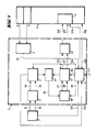
Ein Ausführungsbeispiel der Erfindung wird anhand des in Fig. 1 gezeigten Blockschaltbildes näher erläutert.An embodiment of the invention is explained in more detail with reference to the block diagram shown in FIG. 1.
Es zeigt schematisch eine an sich bekannte Abtasteinrichtung 1 zur Abtastung der Teilung eines Teilungsträgers. Die Abtasteinrichtung 1 gibt zwei um 90° gegeneinander phasenverschobene analoge Abtastsignale S1, S2 an eine Auswerteeinrichtung 2 ab. In Abhängigkeit der Bewegungsrichtung zwischen den zwei zu messenden Objekten werden in einem Richtungsdiskriminator 3 aus den zwei phasenverschobenen analogen Abtastsignalen S1, S2 Zählsignale S3, S4 gebildet.It schematically shows a scanning device 1 known per se for scanning the graduation of a graduation carrier. The scanner 1 is two Analog scanning signals S1, S2 which are phase-shifted from one another by 90 ° to an
Die Auswerteeinrichtung 2 enthält weiterhin einen Absolutwertzähler 4, dem laufend die Zählsignale S3, S4 zugeführt werden. Dieser Absolutwertzähler 4, der Richtungsdiskriminator 3 und die Abtasteinrichtung 1 werden laufend mit Strom versorgt, diese Stromversorgung kann beispielsweise besonders sparsam getaktet betrieben werden. Durch die laufende Stromversorgung ist garantiert, daß der Zählerstand des Absolutwertzählers 4 immer der aktuellen Relativlage entspricht und bei Bedarf ausgegeben werden kann.The
Die Stromversorgung besteht aus einer Haupt-Stromversorgung 5 sowie einer Not-Stromversorgung 6. Beide Stromversorgungen 5 und 6 liegen an einer Überwachungseinrichtung 7 an. Diese Überwachungseinrichtung 7 prüft laufend den Spannungspegel der Haupt-Stromversorgung 5, sobald der Spannungspegel einen vorgegebenen Wert unterschreitet, wird von der Haupt-Stromversorgung 5 auf die Not-Stromversorgung 6 umgeschaltet. Die Haupt-Stromversorgung 5 ist beispielsweise in einer numerischen Steuerung 8 integriert und die Not-Stromversorgung 6 kann eine Batterie oder ein Speicherkondensator sein. Die Not-Stromversorgung 6 ist im gezeigten Beispiel ebenfalls in der numerischen Steuerung 8 enthalten.The power supply consists of a
Mit Hilfe der verschiedenen Betriebsarten soll nun der weitere Aufbau des inkrementalen Positionsmeßsystems erläutert werden.With the help of the different operating modes, the further structure of the incremental position measuring system will now be explained.
Normalbetrieb bedeutet, daß die Haupt-Stromversorgung 5 in Betrieb ist und einen Spannungspegel oberhalb des vorgegebenen Wertes aufweist. Die Überwachungseinrichtung 7 erkennt den Normalbetrieb und liefert ein Anzeigesignal S5 an eine Steuerlogik 9. Die Steuerlogik 9 aktiviert über das Steuersignal S6 einen Pulsgeber 10, der in Abhängigkeit des Zählerstandes des Absolutwertzählers 4 richtungsabhängige Zählsignale S7, S8 an einen Nachlaufzähler 11 abgibt. Die Zählerstände des Absolutwertzählers 4 und des Nachlaufzählers 11 werden mittels eines Komparators 12 laufend miteinander verglichen und der Komparator 12 veranlaßt den Pulsgeber 10 mittels des Steuersignals S9 solange Zählersignale S7, S8 in Form von Vor- oder Rückwärts-Zählimpulsen an den Nachlaufzähler 11 abzugeben, bis beide Zählerstände gleich sind.Normal operation means that the
Dem Nachlaufzähler 11 ist eine Einrichtung 13 nachgeordnet, die in Abhängigkeit der zugeführten Zählsignale S7, S8 die Ausgangssignale S10, S11 des Nachlaufzählers in zwei um 90° gegeneinander phasenverschobene Rechtecksignale S12, S13 wandelt. Diese Rechtecksignale S12, S13 stehen am Ausgang der Auswerteeinrichtung 2 an und werden im gezeigten Beispiel der numerischen Steuerung 8 zugeführt und in einem externen Zähler 14 richtungsabhängig gezählt. Die Einrichtung 13 kann auch dem Pulsgeber 10 nachgeordnet sein und aus den Zählsignalen S7, S8 zwei um 90° gegeneinander phasenverschobene Rechtecksignale S12, S13 bilden.The follow-up
Es ist ersichtlich, daß im Normalbetrieb alle Bausteine des inkrementalen Positionsmeßsystems mit Strom versorgt werden müssen.It can be seen that in normal operation all components of the incremental position measuring system must be supplied with current.
Wird der Zählerstand des Absolutwertzählers 4 Null, so wird vom Absolutwertzähler 4 ein Nullsignal S21 an die Steuerlogik 9 geleitet und bei gleichzeitigem Auftreten eines Referenzsignals S18 ein Nullimpuls S15 von der Auswerteeinrichtung 2 an den Zähler 14 geleitet, der daraufhin auf einen vorgegebenen Wert gesetzt wird.If the count of the absolute value counter 4 becomes zero, the absolute value counter 4 sends a zero signal S21 to the
Notbetrieb bedeutet, daß der Spannungspegel der Haupt-Stromversorgung 5 unter einen vorgegebenen Wert gefallen ist. In diesem Zustand werden zumindest die Abtasteinrichtung 1, der Richtungsdiskriminator 3, der Absolutwertzähler 4 die Überwachungseinrichtung 7 und die Steuerlogik 9 mit Strom versorgt. Die Überwachungseinrichtung 7 liefert ein Anzeigesignal S5 an die Steuerlogik 9, welche den Pulsgeber 10 über das Steuersignal S6 außer Betrieb setzt. Das Anzeigesignal S5 kann auch direkt zum Pulsgeber 10 geführt sein und ihn außer Betrieb setzen.Emergency operation means that the voltage level of the
Im Notbetrieb stehen am Ausgang der Auswerteeinrichtung 2 keine Rechtecksignale S12, S13 an.In emergency operation, there are no square-wave signals S12, S13 at the output of the
Sobald von der Überwachungseinrichtung 7 erkannt wird, daß die Spannung der Haupt-Stromversorgung 5 wieder den vorgegebenen Spannungspegel erreicht oder überschritten hat, wird vom Notbetrieb auf den Normalbetrieb umgeschaltet. Dabei werden folgende Schritte durchgeführt:
- die
Überwachungseinrichtung 7 liefert ein Anzeigesignal S5 zurSteuerlogik 9; - die
Steuerlogik 9 liefert ein Resetsignal S14 an denNachlaufzähler 11, der dadurch auf Null gesetzt wird; - Ausgabe eines synthetisch erzeugten Nullimpulses S15 von der
Auswerteeinrichtung 2 an denZähler 14 der numerischen Steuerung 8, wodurch dieserZähler 14 auf einen bestimmten Wert gesetzt wird; - Aktivieren des
Pulsgebers 10 und somit Starten desNachlaufzählers 11; - Abgabe von um 90° gegeneinander phasenverschobenen Rechtecksignalen S12, S13 aus der
Auswerteeinrichtung 2 zumZähler 14, bis derKomparator 12 den Gleichstand zwischen dem Absolutwertzähler 4 und demNachlaufzähler 11 festgestellt hat.
- the
monitoring device 7 supplies a display signal S5 to thecontrol logic 9; - the
control logic 9 supplies a reset signal S14 to thelag counter 11, which is thereby set to zero; - Output of a synthetically generated zero pulse S15 from the
evaluation device 2 to thecounter 14 of the numerical control 8, whereby thiscounter 14 is set to a specific value; - Activating the
pulse generator 10 and thus starting thelag counter 11; - Output of square-wave signals S12, S13, which are phase-shifted with respect to one another, from the
evaluation device 2 to thecounter 14 until thecomparator 12 has determined the equality between the absolute value counter 4 and thelag counter 11.
Mit diesem inkremetalen Positionsmeßsystem ist es besonders einfach, an beliebiger Stelle eine absolute Nullposition zu setzen. Wird beispielsweise als Teilungsträger ein Längenmaßstab mit mehreren Referenzmarken verwendet, so kann einer beliebigen Referenzmarke die absolute Nullposition zugeordnet werden. Hierzu wird bei Ablesung dieser ausgewählten Referenzmarke der Absolutwertzähler 4 und der Nachlaufzähler 11 mittels des Resetsignals S16 auf Null gesetzt. Die Auswahl der Referenzmarke kann dadurch erfolgen, daß an der Steuerlogik 9 ein Bezugssignal S17 anliegt, das mit dem Referenzsignal S18 logisch UND- verknüpft wird. Das Bezugssignal S17 wird vorzugsweise durch Antasten einer Bezugskante erzeugt. Das Resetsignal S16 wird also nur dann abgegeben, wenn gleichzeitig das Bezugssignal S17 und das Referenzsignal S18 an der Steuerlogik 9 anstehen.With this incremental position measuring system, it is particularly easy to set an absolute zero position at any point. If, for example, a length scale with several reference marks is used as the graduation carrier, the absolute zero position can be assigned to any reference mark. For this purpose, when reading this selected reference mark, the absolute value counter 4 and the
Der Zähler 14 der numerischen Steuerung 8 wird beim Setzen bzw. beim Erkennen der absoluten Nullposition auf einen bestimmten Wert gesetzt, der vorzugsweise auch Null ist. Der Wert kann aber auch von Null abweichen, wenn die absolute Nullposition der numerischen Steuerung 8 nicht mit der absoluten Nullposition des Positionsmeßsystems übereinstimmt.The
Das gleiche Verfahren ist beim Abtasten einer Teilscheibe mit einer Referenzmarke anwendbar. Hier wird die Referenzmarke nach einer bestimmten Anzahl von Umdrehungen beim Auftreten des Bezugssignals S17 als absolute Nullposition festgelegt.The same procedure can be used when scanning a graduated disk with a reference mark. Here, the reference mark is defined as an absolute zero position after a certain number of revolutions when the reference signal S17 occurs.
Der Absolutwertzähler 4 besteht vorzugsweise aus zwei Zählern. Bei Verwendung eines Drehgebers als Positionsmeßsystem ist ein Zähler zur Erfassung der Umdrehungen und ein Zähler zur Erfassung der Position innerhalb einer Umdrehung vorgesehen. Bei Längenmeßsystemen kann mit dem ersten Zähler die Anzahl der Referenzmarken und mit dem zweiten Zähler die Position zwischen den Referenzmarken erfaßt werden.The absolute value counter 4 preferably consists of two counters. When using a rotary encoder as a position measuring system, a counter for detecting the revolutions and a counter for detecting the position within one revolution are provided. In length measuring systems, the number of reference marks can be recorded with the first counter and the position between the reference marks with the second counter.
Es wurde bereits ausführlich erläutert, daß mittels des Anzeigesignals S5 die Betriebsart von der Überwachungseinrichtung 7 zur Steuerlogik 9 gemeldet wird. Wenn die Überwachungseinrichtung 7 Normalbetrieb erkennt, wird von der Steuerlogik 9 und somit von der Auswerteeinrichtung 2 ein Bereitschaftssignal S19 zur numerischen Steuerung 8 geleitet. Die numerische Steuerung 8 oder der Zähler 14 meldet ebenfalls der Auswerteeinrichtung 2, mit dem Bereitschaftssignal S20, wenn Bereitschaft zum Empfang der phasenverschobenen Rechtecksignale S12, S13 besteht. Besonders vorteilhaft ist es, wenn auf Normalbetrieb nur dann umgestellt wird, wenn die Bereitschaftssignale S19 und S20 anstehen, dabei können beide Bereitschaftssignale S19 und S20 an einer Signalleitung anstehen. Diese Signalleitung wird somit bidirektional z.B. mittels einer Open Collector-Schaltung betrieben.It has already been explained in detail that the operating mode of the
Claims (14)
Priority Applications (1)
| Application Number | Priority Date | Filing Date | Title |
|---|---|---|---|
| AT9191103460T ATE105404T1 (en) | 1990-04-09 | 1991-03-07 | INCREMENTAL POSITION MEASUREMENT SYSTEM. |
Applications Claiming Priority (2)
| Application Number | Priority Date | Filing Date | Title |
|---|---|---|---|
| DE4011411 | 1990-04-09 | ||
| DE4011411A DE4011411C2 (en) | 1990-04-09 | 1990-04-09 | Incremental position measuring system |
Publications (2)
| Publication Number | Publication Date |
|---|---|
| EP0451505A1 true EP0451505A1 (en) | 1991-10-16 |
| EP0451505B1 EP0451505B1 (en) | 1994-05-04 |
Family
ID=6404045
Family Applications (1)
| Application Number | Title | Priority Date | Filing Date |
|---|---|---|---|
| EP91103460A Expired - Lifetime EP0451505B1 (en) | 1990-04-09 | 1991-03-07 | Incremental position measuring system |
Country Status (5)
| Country | Link |
|---|---|
| US (1) | US5131017A (en) |
| EP (1) | EP0451505B1 (en) |
| JP (1) | JP2648740B2 (en) |
| AT (1) | ATE105404T1 (en) |
| DE (2) | DE4011411C2 (en) |
Cited By (2)
| Publication number | Priority date | Publication date | Assignee | Title |
|---|---|---|---|---|
| GB2268273A (en) * | 1992-06-26 | 1994-01-05 | Mitutoyo Corp | A capacitance-type measuring device |
| FR2703450A1 (en) * | 1993-03-31 | 1994-10-07 | Aut Comp | Absolute incremental numerical encoder, installation and machine comprising this encoder |
Families Citing this family (8)
| Publication number | Priority date | Publication date | Assignee | Title |
|---|---|---|---|---|
| ATE302404T1 (en) * | 1997-04-16 | 2005-09-15 | Heidenhain Gmbh Dr Johannes | POSITION MEASURING DEVICE AND METHOD FOR OPERATING THE SAME |
| DE19806099A1 (en) * | 1997-05-21 | 1998-11-26 | Bosch Gmbh Robert | Method for operating a position sensor |
| EP0880013B1 (en) * | 1997-05-21 | 2003-04-09 | Robert Bosch Gmbh | Operating method for a positioning sensor |
| EP1056989B1 (en) * | 1998-02-21 | 2002-12-18 | Dr. Johannes Heidenhain GmbH | Method for operating a position measuring system and corresponding position measuring system |
| US6181423B1 (en) | 1998-10-06 | 2001-01-30 | Jorge Uriarte | Linear encoder providing engagement by engraving |
| DE10055996A1 (en) | 2000-11-11 | 2002-05-23 | Heidenhain Gmbh Dr Johannes | Position measuring device and method for commissioning a position measuring device |
| DE10117194B4 (en) * | 2001-04-05 | 2013-09-19 | Anton Rodi | Angle or displacement encoder |
| EP3124920B1 (en) * | 2015-07-27 | 2017-11-01 | Dr. Johannes Heidenhain GmbH | Positioning device and method for the operation thereof |
Citations (2)
| Publication number | Priority date | Publication date | Assignee | Title |
|---|---|---|---|---|
| DE2747208A1 (en) * | 1977-08-12 | 1979-02-15 | Rieder | MEASURING DEVICE, IN PARTICULAR LENGTH MEASURING DEVICE ON MACHINE TOOLS OR DGL. |
| DE2732909B2 (en) * | 1977-07-21 | 1979-03-15 | Dr. Johannes Heidenhain Gmbh, 8225 Traunreut | Incremental position system |
Family Cites Families (13)
| Publication number | Priority date | Publication date | Assignee | Title |
|---|---|---|---|---|
| JPS5199418A (en) * | 1975-02-27 | 1976-09-02 | Laurel Bank Machine Co | Teidenjino ic memoriihojikairo |
| US4064501A (en) * | 1975-08-28 | 1977-12-20 | Unitrol, Inc. | Control system |
| US4224506A (en) * | 1978-03-24 | 1980-09-23 | Pitney Bowes Inc. | Electronic counter with non-volatile memory |
| AT373690B (en) * | 1980-06-11 | 1984-02-10 | Rieder Heinz | MEASURING DEVICE, SPECIAL LENGTH OR ANGLE MEASURING DEVICE |
| JPS6148303U (en) * | 1984-09-04 | 1986-04-01 | ||
| JPS61120903A (en) * | 1984-11-19 | 1986-06-09 | Sumitomo Electric Ind Ltd | Angle detecting circuit |
| JPS61154316A (en) * | 1984-12-27 | 1986-07-14 | Toshiba Corp | Position detector |
| JPS61184409A (en) * | 1985-02-12 | 1986-08-18 | Amada Metoretsukusu:Kk | Apparatus for detecting position of moving body |
| DE3604160A1 (en) * | 1986-02-10 | 1987-09-10 | T & R Electronic Gmbh | Auxiliary device in connection with an electronic counter control device |
| JPS63187106A (en) * | 1987-01-30 | 1988-08-02 | Mitsubishi Heavy Ind Ltd | Absolute position detector |
| JPS63205507A (en) * | 1987-02-21 | 1988-08-25 | Fanuc Ltd | Detection system for absolute position |
| JPS6445590A (en) * | 1987-08-11 | 1989-02-20 | Kobe Steel Ltd | Absolute rotational angle detector for industrial robot |
| JPH01237415A (en) * | 1988-03-17 | 1989-09-21 | Fuji Electric Co Ltd | Encoder monitoring apparatus |
-
1990
- 1990-04-09 DE DE4011411A patent/DE4011411C2/en not_active Expired - Fee Related
-
1991
- 1991-03-07 AT AT9191103460T patent/ATE105404T1/en not_active IP Right Cessation
- 1991-03-07 EP EP91103460A patent/EP0451505B1/en not_active Expired - Lifetime
- 1991-03-07 DE DE59101535T patent/DE59101535D1/en not_active Expired - Fee Related
- 1991-04-08 US US07/681,882 patent/US5131017A/en not_active Expired - Lifetime
- 1991-04-09 JP JP3076468A patent/JP2648740B2/en not_active Expired - Fee Related
Patent Citations (2)
| Publication number | Priority date | Publication date | Assignee | Title |
|---|---|---|---|---|
| DE2732909B2 (en) * | 1977-07-21 | 1979-03-15 | Dr. Johannes Heidenhain Gmbh, 8225 Traunreut | Incremental position system |
| DE2747208A1 (en) * | 1977-08-12 | 1979-02-15 | Rieder | MEASURING DEVICE, IN PARTICULAR LENGTH MEASURING DEVICE ON MACHINE TOOLS OR DGL. |
Cited By (3)
| Publication number | Priority date | Publication date | Assignee | Title |
|---|---|---|---|---|
| GB2268273A (en) * | 1992-06-26 | 1994-01-05 | Mitutoyo Corp | A capacitance-type measuring device |
| GB2268273B (en) * | 1992-06-26 | 1996-01-24 | Mitutoyo Corp | A capacitance-type measuring device |
| FR2703450A1 (en) * | 1993-03-31 | 1994-10-07 | Aut Comp | Absolute incremental numerical encoder, installation and machine comprising this encoder |
Also Published As
| Publication number | Publication date |
|---|---|
| DE4011411C2 (en) | 1993-09-30 |
| DE59101535D1 (en) | 1994-06-09 |
| EP0451505B1 (en) | 1994-05-04 |
| JP2648740B2 (en) | 1997-09-03 |
| DE4011411A1 (en) | 1991-10-10 |
| US5131017A (en) | 1992-07-14 |
| ATE105404T1 (en) | 1994-05-15 |
| JPH04225110A (en) | 1992-08-14 |
Similar Documents
| Publication | Publication Date | Title |
|---|---|---|
| DE4342377B4 (en) | Arrangement and method for serial data transmission of a position measuring device | |
| EP1193472B1 (en) | Method and apparatus for determining the absolute position of displacement and angle sensors | |
| DE2716775C2 (en) | ||
| EP1987316B1 (en) | Reliable monitoring of the speed in coordinate measuring appliances | |
| DE4330823C2 (en) | Drive device with a safety device for special operation | |
| DE112013006990B4 (en) | Encoder and servo motor | |
| DE3324333C2 (en) | Method for monitoring an electronically controlled screwdriver | |
| EP1856485B1 (en) | Two-channel method for continuously determining at least one output signal from varying input signals | |
| EP0451505B1 (en) | Incremental position measuring system | |
| EP0085161A2 (en) | Digital electric length or angle measuring device | |
| DE2847779C3 (en) | Device for position detection in numerically controlled machine tools | |
| EP0066682B1 (en) | Positioning device | |
| DE2111635A1 (en) | Device for converting the phase position of a signal into a sequence of pulses | |
| EP0833130B1 (en) | Position measuring system and method | |
| DE3635305A1 (en) | POSITION CONTROL UNIT | |
| DE3424246C2 (en) | Method for monitoring a drive system | |
| DE3417016C1 (en) | Method for determining the position and speed of objects | |
| EP3035000B1 (en) | Device and method for checking a work cycle signal of a position measurement device | |
| EP1614990B2 (en) | Position sensor and method therefore | |
| EP2505965A2 (en) | Method and monitoring unit for testing position values | |
| EP0270837A1 (en) | Method and apparatus for the position regulation of motor-driven parts on an NC and CNC machine tool | |
| EP0100391B1 (en) | Circuit arrangement for a cyclic absolute position measuring system | |
| DE19604968C2 (en) | Method for testing incremental measuring systems and testing device for carrying out the method | |
| DE102020201282A1 (en) | Position measuring device and method for its operation | |
| DE102021105352A1 (en) | Sensor, in particular torque or angle of rotation sensor |
Legal Events
| Date | Code | Title | Description |
|---|---|---|---|
| PUAI | Public reference made under article 153(3) epc to a published international application that has entered the european phase |
Free format text: ORIGINAL CODE: 0009012 |
|
| 17P | Request for examination filed |
Effective date: 19910319 |
|
| AK | Designated contracting states |
Kind code of ref document: A1 Designated state(s): AT CH DE FR GB IT LI |
|
| 17Q | First examination report despatched |
Effective date: 19930422 |
|
| ITF | It: translation for a ep patent filed |
Owner name: DE DOMINICIS & MAYER S.R.L. |
|
| GRAA | (expected) grant |
Free format text: ORIGINAL CODE: 0009210 |
|
| AK | Designated contracting states |
Kind code of ref document: B1 Designated state(s): AT CH DE FR GB IT LI |
|
| REF | Corresponds to: |
Ref document number: 105404 Country of ref document: AT Date of ref document: 19940515 Kind code of ref document: T |
|
| ET | Fr: translation filed | ||
| REF | Corresponds to: |
Ref document number: 59101535 Country of ref document: DE Date of ref document: 19940609 |
|
| GBT | Gb: translation of ep patent filed (gb section 77(6)(a)/1977) |
Effective date: 19940517 |
|
| PLBE | No opposition filed within time limit |
Free format text: ORIGINAL CODE: 0009261 |
|
| STAA | Information on the status of an ep patent application or granted ep patent |
Free format text: STATUS: NO OPPOSITION FILED WITHIN TIME LIMIT |
|
| 26N | No opposition filed | ||
| PGFP | Annual fee paid to national office [announced via postgrant information from national office to epo] |
Ref country code: AT Payment date: 20010226 Year of fee payment: 11 |
|
| REG | Reference to a national code |
Ref country code: GB Ref legal event code: IF02 |
|
| PGFP | Annual fee paid to national office [announced via postgrant information from national office to epo] |
Ref country code: GB Payment date: 20020222 Year of fee payment: 12 |
|
| PGFP | Annual fee paid to national office [announced via postgrant information from national office to epo] |
Ref country code: CH Payment date: 20020225 Year of fee payment: 12 |
|
| PG25 | Lapsed in a contracting state [announced via postgrant information from national office to epo] |
Ref country code: AT Free format text: LAPSE BECAUSE OF NON-PAYMENT OF DUE FEES Effective date: 20020307 |
|
| PGFP | Annual fee paid to national office [announced via postgrant information from national office to epo] |
Ref country code: FR Payment date: 20020315 Year of fee payment: 12 |
|
| PG25 | Lapsed in a contracting state [announced via postgrant information from national office to epo] |
Ref country code: GB Free format text: LAPSE BECAUSE OF NON-PAYMENT OF DUE FEES Effective date: 20030307 |
|
| PG25 | Lapsed in a contracting state [announced via postgrant information from national office to epo] |
Ref country code: LI Free format text: LAPSE BECAUSE OF NON-PAYMENT OF DUE FEES Effective date: 20030331 Ref country code: CH Free format text: LAPSE BECAUSE OF NON-PAYMENT OF DUE FEES Effective date: 20030331 |
|
| GBPC | Gb: european patent ceased through non-payment of renewal fee |
Effective date: 20030307 |
|
| REG | Reference to a national code |
Ref country code: CH Ref legal event code: PL |
|
| PG25 | Lapsed in a contracting state [announced via postgrant information from national office to epo] |
Ref country code: FR Free format text: LAPSE BECAUSE OF NON-PAYMENT OF DUE FEES Effective date: 20031127 |
|
| REG | Reference to a national code |
Ref country code: FR Ref legal event code: ST |
|
| PG25 | Lapsed in a contracting state [announced via postgrant information from national office to epo] |
Ref country code: IT Free format text: LAPSE BECAUSE OF NON-PAYMENT OF DUE FEES;WARNING: LAPSES OF ITALIAN PATENTS WITH EFFECTIVE DATE BEFORE 2007 MAY HAVE OCCURRED AT ANY TIME BEFORE 2007. THE CORRECT EFFECTIVE DATE MAY BE DIFFERENT FROM THE ONE RECORDED. Effective date: 20050307 |
|
| PGFP | Annual fee paid to national office [announced via postgrant information from national office to epo] |
Ref country code: DE Payment date: 20060314 Year of fee payment: 16 |
|
| PG25 | Lapsed in a contracting state [announced via postgrant information from national office to epo] |
Ref country code: DE Free format text: LAPSE BECAUSE OF NON-PAYMENT OF DUE FEES Effective date: 20071002 |