EP0066682B1 - Positioning device - Google Patents
Positioning device Download PDFInfo
- Publication number
- EP0066682B1 EP0066682B1 EP82102663A EP82102663A EP0066682B1 EP 0066682 B1 EP0066682 B1 EP 0066682B1 EP 82102663 A EP82102663 A EP 82102663A EP 82102663 A EP82102663 A EP 82102663A EP 0066682 B1 EP0066682 B1 EP 0066682B1
- Authority
- EP
- European Patent Office
- Prior art keywords
- speed
- monitoring circuit
- machine component
- movable machine
- signal
- Prior art date
- Legal status (The legal status is an assumption and is not a legal conclusion. Google has not performed a legal analysis and makes no representation as to the accuracy of the status listed.)
- Expired
Links
Images


Classifications
-
- G—PHYSICS
- G05—CONTROLLING; REGULATING
- G05B—CONTROL OR REGULATING SYSTEMS IN GENERAL; FUNCTIONAL ELEMENTS OF SUCH SYSTEMS; MONITORING OR TESTING ARRANGEMENTS FOR SUCH SYSTEMS OR ELEMENTS
- G05B19/00—Programme-control systems
- G05B19/02—Programme-control systems electric
- G05B19/18—Numerical control [NC], i.e. automatically operating machines, in particular machine tools, e.g. in a manufacturing environment, so as to execute positioning, movement or co-ordinated operations by means of programme data in numerical form
- G05B19/19—Numerical control [NC], i.e. automatically operating machines, in particular machine tools, e.g. in a manufacturing environment, so as to execute positioning, movement or co-ordinated operations by means of programme data in numerical form characterised by positioning or contouring control systems, e.g. to control position from one programmed point to another or to control movement along a programmed continuous path
- G05B19/21—Numerical control [NC], i.e. automatically operating machines, in particular machine tools, e.g. in a manufacturing environment, so as to execute positioning, movement or co-ordinated operations by means of programme data in numerical form characterised by positioning or contouring control systems, e.g. to control position from one programmed point to another or to control movement along a programmed continuous path using an incremental digital measuring device
- G05B19/23—Numerical control [NC], i.e. automatically operating machines, in particular machine tools, e.g. in a manufacturing environment, so as to execute positioning, movement or co-ordinated operations by means of programme data in numerical form characterised by positioning or contouring control systems, e.g. to control position from one programmed point to another or to control movement along a programmed continuous path using an incremental digital measuring device for point-to-point control
- G05B19/231—Numerical control [NC], i.e. automatically operating machines, in particular machine tools, e.g. in a manufacturing environment, so as to execute positioning, movement or co-ordinated operations by means of programme data in numerical form characterised by positioning or contouring control systems, e.g. to control position from one programmed point to another or to control movement along a programmed continuous path using an incremental digital measuring device for point-to-point control the positional error is used to control continuously the servomotor according to its magnitude
- G05B19/232—Numerical control [NC], i.e. automatically operating machines, in particular machine tools, e.g. in a manufacturing environment, so as to execute positioning, movement or co-ordinated operations by means of programme data in numerical form characterised by positioning or contouring control systems, e.g. to control position from one programmed point to another or to control movement along a programmed continuous path using an incremental digital measuring device for point-to-point control the positional error is used to control continuously the servomotor according to its magnitude with speed feedback only
-
- G—PHYSICS
- G05—CONTROLLING; REGULATING
- G05B—CONTROL OR REGULATING SYSTEMS IN GENERAL; FUNCTIONAL ELEMENTS OF SUCH SYSTEMS; MONITORING OR TESTING ARRANGEMENTS FOR SUCH SYSTEMS OR ELEMENTS
- G05B2219/00—Program-control systems
- G05B2219/30—Nc systems
- G05B2219/34—Director, elements to supervisory
- G05B2219/34215—Microprocessor
-
- G—PHYSICS
- G05—CONTROLLING; REGULATING
- G05B—CONTROL OR REGULATING SYSTEMS IN GENERAL; FUNCTIONAL ELEMENTS OF SUCH SYSTEMS; MONITORING OR TESTING ARRANGEMENTS FOR SUCH SYSTEMS OR ELEMENTS
- G05B2219/00—Program-control systems
- G05B2219/30—Nc systems
- G05B2219/34—Director, elements to supervisory
- G05B2219/34466—Bad circuits, watchdog, alarm, indication
-
- G—PHYSICS
- G05—CONTROLLING; REGULATING
- G05B—CONTROL OR REGULATING SYSTEMS IN GENERAL; FUNCTIONAL ELEMENTS OF SUCH SYSTEMS; MONITORING OR TESTING ARRANGEMENTS FOR SUCH SYSTEMS OR ELEMENTS
- G05B2219/00—Program-control systems
- G05B2219/30—Nc systems
- G05B2219/42—Servomotor, servo controller kind till VSS
- G05B2219/42309—Excess in speed
-
- Y—GENERAL TAGGING OF NEW TECHNOLOGICAL DEVELOPMENTS; GENERAL TAGGING OF CROSS-SECTIONAL TECHNOLOGIES SPANNING OVER SEVERAL SECTIONS OF THE IPC; TECHNICAL SUBJECTS COVERED BY FORMER USPC CROSS-REFERENCE ART COLLECTIONS [XRACs] AND DIGESTS
- Y10—TECHNICAL SUBJECTS COVERED BY FORMER USPC
- Y10S—TECHNICAL SUBJECTS COVERED BY FORMER USPC CROSS-REFERENCE ART COLLECTIONS [XRACs] AND DIGESTS
- Y10S388/00—Electricity: motor control systems
- Y10S388/90—Specific system operational feature
- Y10S388/903—Protective, e.g. voltage or current limit
-
- Y—GENERAL TAGGING OF NEW TECHNOLOGICAL DEVELOPMENTS; GENERAL TAGGING OF CROSS-SECTIONAL TECHNOLOGIES SPANNING OVER SEVERAL SECTIONS OF THE IPC; TECHNICAL SUBJECTS COVERED BY FORMER USPC CROSS-REFERENCE ART COLLECTIONS [XRACs] AND DIGESTS
- Y10—TECHNICAL SUBJECTS COVERED BY FORMER USPC
- Y10S—TECHNICAL SUBJECTS COVERED BY FORMER USPC CROSS-REFERENCE ART COLLECTIONS [XRACs] AND DIGESTS
- Y10S388/00—Electricity: motor control systems
- Y10S388/907—Specific control circuit element or device
- Y10S388/909—Monitoring means
-
- Y—GENERAL TAGGING OF NEW TECHNOLOGICAL DEVELOPMENTS; GENERAL TAGGING OF CROSS-SECTIONAL TECHNOLOGIES SPANNING OVER SEVERAL SECTIONS OF THE IPC; TECHNICAL SUBJECTS COVERED BY FORMER USPC CROSS-REFERENCE ART COLLECTIONS [XRACs] AND DIGESTS
- Y10—TECHNICAL SUBJECTS COVERED BY FORMER USPC
- Y10S—TECHNICAL SUBJECTS COVERED BY FORMER USPC CROSS-REFERENCE ART COLLECTIONS [XRACs] AND DIGESTS
- Y10S388/00—Electricity: motor control systems
- Y10S388/907—Specific control circuit element or device
- Y10S388/912—Pulse or frequency counter
-
- Y—GENERAL TAGGING OF NEW TECHNOLOGICAL DEVELOPMENTS; GENERAL TAGGING OF CROSS-SECTIONAL TECHNOLOGIES SPANNING OVER SEVERAL SECTIONS OF THE IPC; TECHNICAL SUBJECTS COVERED BY FORMER USPC CROSS-REFERENCE ART COLLECTIONS [XRACs] AND DIGESTS
- Y10—TECHNICAL SUBJECTS COVERED BY FORMER USPC
- Y10S—TECHNICAL SUBJECTS COVERED BY FORMER USPC CROSS-REFERENCE ART COLLECTIONS [XRACs] AND DIGESTS
- Y10S388/00—Electricity: motor control systems
- Y10S388/907—Specific control circuit element or device
- Y10S388/915—Sawtooth or ramp waveform generator
Definitions
- the invention relates to a device according to the preamble of claim 1.
- US-A-3996454 describes a speed monitoring device which can monitor a lower and an upper limit speed, but which is not designed in such a way that malfunctions of the components can be detected.
- GB-A-2 065 328 shows a device for positioning machine components which can be displaced relative to one another, with a drive device for a movable machine component.
- the control device interacts with a monitoring circuit in which the actual speed of the machine components that are movable relative to one another are compared with the corresponding setpoint values specified by the control device.
- this monitoring circuit there is a combination of binary signals derived from the aforementioned actual and setpoints, so that an error message can be output. if the predefinable combination of binary signals is not permitted, that is, if the actual speed of the moving part exceeds the permitted speed.
- a positioning system is described in the German magazine “ELEKTRONIK” 1980, number 18, pages 47 to 54, in which variable quantities that can be predetermined electronically can be converted into spatial positions by means of electromechanical components.
- a speed control circuit is provided, with the aid of which the drive motor can be controlled so that the setpoint value of the speed is reached after starting, and that the speed is reduced again before reaching the end position so that the end position is not exceeded.
- the invention is based on the object of developing a device of the type mentioned at the outset such that as many assemblies as possible of a positioning device are monitored and the positioning device can thereby be operated even more reliably.
- the advantages of the invention lie in the high operational reliability of the entire positioning device, since both the actual measuring device (the signal generator generating the actual position values) and the measuring signal processing unit, the directional discriminator, the servo device, the digital-to-analog converter and the components of the monitoring circuit be monitored for their proper functioning.
- a signal transmitter designed as a length measuring device L is attached according to FIG. 1 in the usual way to the bed 1 or to the carriage 2 of a machine tool.
- the length measuring device L works incrementally and is of the type described, for example, in DE-C-2 505 585.
- a control device S controls a drive device M as a function of program data, which moves the carriage 2 relative to the bed 1 via a spindle 3. This movement is registered by the length measuring device L, which now feeds measurement signals as actual position values a1, a2 into the control device S, where they are processed together with program data.
- Both the measurement signal a1 prepared for the actual speed value V1 and the values derived from the program data for the movement of the machine components 1 and 2 are input into a speed monitoring circuit G.
- a warning lamp W is connected to the output Ga of the speed monitoring circuit G via a fail-safe network F which signals an alarm when the actual movement speed (the actual value) of the machine components 1 and 2 which are movable relative to one another deviates from the setpoint of the speed.
- the error signal can also cause an acoustic warning or stop the machine automatically.
- the block diagram in FIG. 2 contains the essential electrical elements of the monitoring device.
- the measurement signals a1, a2 generated by the incremental length measuring device L are amplified, triggered and, if necessary, interpolated to form an intermediate value in a measurement signal processing unit E.
- the binary measurement signals Ual, Ua1 prepared in this way are fed to a direction discriminator RD for detecting the direction of movement, from which the measurement signals are fed as up / down signals V4 / R4 into an up / down counter Z and their sum as a digital value in a connected to the counter Z.
- Display device D can be displayed numerically.
- the binary measurement signals Ual, Ua2 become further signals V1 / R1.
- V2 / R2 derived, the signal V1 / P1 one pulse, the signal V2 / R2 two pulses and the signal V4 / R4 four pulses per measurement signal period.
- the forward / backward signals V4 / R4 summed up to a digital value in the counter Z are fed to a digital computer f lC, which thus has the actual value for the position of the machine components 1 and 2 relative to one another.
- a digital computer f lC which thus has the actual value for the position of the machine components 1 and 2 relative to one another.
- T keyboard, magnetic tape, punched tape and the like
- the setpoint for the position of the machine components 1 and 2 can be entered as a digital value in the digital computer f lC.
- the digital computer ⁇ C calculates whether the position of the machine components 1 and 2 must be changed and, if the position needs to be changed, outputs a digital value at its output that represents a movement setpoint, i.e. proportionally a shift speed.
- this digital value is applied to a unit 4 which contains a digital-to-analog converter DAU 1 and an amplifier AMP.
- the drive device M is acted upon by this unit with a voltage corresponding to the setpoint value of the displacement speed.
- the drive device M can also contain further components 5 (servo device, tachometer generator and the like).
- this digital value is fed into the monitoring circuit G, where it is converted according to FIG. 3 by a digital-to-analog converter DAU 2 into a current proportional to the setpoint of the displacement speed.
- This current charges a capacitor C, the voltage Uc of which increases in proportion to the charging time.
- a direction comparator module 6 From the direction-dependent binary measurement signals V4 / R4. which feed the counter Z from the direction discriminator RD, derived forward / backward signals V1 and R1 are fed to a direction comparator module 6. At another input of the direction comparator module 6 there is counting direction-dependent sign information coming from the digital computer ⁇ C, which is linked with the forward / reverse signals V1 and R1 in a known manner so that a binary signal V1 / R1 only then at the output of the direction comparator module 6 is present when the sign information (positive or negative) output by the digital computer ⁇ C matches the forward or reverse signal V1 or R1, i. H. if there is directional coincidence. In a divider module 7, the binary output signal from the direction comparator module 6 is divided down to half the clock frequency and then fed as signal B into the monitoring circuit G.
- this signal B derived from the converted measurement signals Ua1, Ua2, is fed to the discharge circuit 8 in the monitoring circuit G, the switching stage 9 periodically discharging the capacitor C, the discharge period being determined by the clock frequency of the latter signal B. .
- a so-called sawtooth voltage Uc is applied to the capacitor C during the positioning, the course of which is determined by the setpoint for the speed of movement of the machine components 1 and 2 and indirectly by the measurement signals a1, a2 generated by the signal generator L.
- the sawtooth voltage Uc causes Vmax at the outputs of two triggers 13. 14 with different trigger thresholds.
- Vmin generates two binary signal sequences C for Vmax and D for Vmin.
- the binary signals C and D are linked via logic elements 10, 11 and 12, so that a combination of binary signals is present at the output Ga of the monitoring circuit G, from which an error message can be derived, which causes an optical or acoustic alarm signal, or the movement machine parts 1 and 2 stops.
- the combination of binary signals can also be connected to a fail-safe network F. so that largely all elements of the positioning device can be monitored fail-safe.
- a fail-safe network is e.g. B. described in DE-C-2 207 224.
- Such a network could be adapted by a person skilled in the art to the requirements of the above positioning device.
- FIG. 4 shows various signal profiles by means of which the above-described processes are to be explained again.
- a binary signal Ua1 changes its states periodically with a period GK.
- This binary signal Ua1 is derived from the analog measurement signal which represents the actual position value a1 (FIG. 1).
- the periodicity arises from the scanning of a grating scale, which is part of the incremental length measuring device L, and whose division consists of a number of parallel lines, the Lattice constant is equal to GK.
- the analog measurement signal a1 is amplified, triggered and possibly multiplied by interpolation.
- the binary signal Ua1 is then present at the output of the measurement signal processing unit E.
- a further analog measuring signal a2 is generated by the length measuring device L, which is shifted by 90 ° with respect to the measuring signal a1. This signal is required to detect the direction of movement of the components to be measured and is processed in the same way as the analog measurement signal a1.
- Two binary signals Ua1 and Ua2 are thus present at the output of the measurement signal processing unit E.
- these binary signals Ua1 and Ua2 are fed into a direction discriminator RD, in which the direction of movement of the machine components 1 and 2 to be measured is determined, and the signals V1 / R1, V2 / R2 and V4 / R4 are generated.
- the signals V1. V2 and V4 are defined as forward movement signals
- signals R1, R2 and R4 are defined as backward movement signals.
- FIG. V2 and V4 shows only signals V1 representing the forward pulses.
- a binary signal B with half the frequency of the signal V1 is generated from the signal V1 in the divider circuit 7 (FIG. 2).
- the edge-synchronous profile of the signals described can be seen from the graphical representation of the signal profiles in FIG. 4.
- the sawtooth-shaped voltage profile Uc on capacitor C is shown, as explained with reference to FIG. 3.
- the current proportional to the setpoint of the shifting speed specified by the control device S begins to charge the capacitor C after the time to, the voltage of which rises over the course of time t, which becomes clear from the continuously drawn rising line.
- the signal B then discharges.
- the horizontal lines drawn in dash-dot lines indicate the position of the trigger thresholds Wmax and Vmin.
- the intersections of the sawtooth-shaped voltage curve Uc with the trigger thresholds Vmin and Vmax indicate the trigger points and the binary signals C and D are generated, the trigger stage 14 generating the signal C and the trigger stage 13 the signal D.
- the state combination of the binary signals C and D is then checked to determine whether there is error-free operation or whether there is a fault.
- t1, t2, t3 which are precisely determined by the pulses of signals V1 and V2, and which thus depend on the frequency of the processed measurement signals a1 and a2, the states of signals C and D are checked.
- the combination of statuses at various test times shows whether there is trouble-free operation. Trouble-free operation is when the following «truth table is fulfilled:
- the binary state of both signals C and D must be "H”. If this combination exists, the positioning is error-free.
- the dashed curve of the capacitor voltage U'c represents incorrect operation of the positioning device. In this case, the actual displacement speed is too low.
- the charging current derived from the setpoint for the shifting movement leads to the voltage curve U'c at capacitor C shown in broken lines.
- the discharge time to, which is derived from the measurement signals is delayed.
- a higher capacitor voltage U'c is present at capacitor C at time to.
- the rise in the capacitor voltage U'c is therefore steeper in relation to the measurement signal frequency (number of measurement signal periods per unit of time) than in normal operation.
- a monitoring device could also be designed in such a way that the displacement speed of the machine components 1 and 2 is monitored in two areas with different tolerances.
- the person skilled in the art will provide three or four triggers with different trigger thresholds, so that only a warning area can be determined from a first area of the first trigger thresholds by an optical and / or acoustic warning. However, if the warning range defined by these first triggers is exceeded or undershot, the displacement movement is interrupted automatically.
- This stopping range can be defined by other triggers with other trigger thresholds.
- the automatic movement movement can be interrupted if a certain dwell time in the warning area is exceeded.
Abstract
Description
Die Erfindung bezieht sich auf eine Einrichtung nach dem Oberbegriff des Anspruches 1.The invention relates to a device according to the preamble of
Derartige Einrichtungen sind bekannt. In der US-A-3996454 ist eine Geschwindigkeitsüberwachungseinrichtung beschrieben, die zwar eine untere und eine obere Grenzgeschwindigkeit überwachen kann, die jedoch nicht so ausgelegt ist, daß Fehlfunktionen der Bauelemente erkannt werden können.Such devices are known. US-A-3996454 describes a speed monitoring device which can monitor a lower and an upper limit speed, but which is not designed in such a way that malfunctions of the components can be detected.
Eine ähnliche Schaltung zur Überwachung einer oberen Grenzgeschwindigkeit ist in der US-A-3 778 696 beschrieben. Auch dieses Schaltung kann eigene Fehlfunktionen nicht erkennen.A similar circuit for monitoring an upper limit speed is described in US-A-3,778,696. Even this circuit cannot recognize its own malfunctions.
Die GB-A-2 065 328 zeigt eine Einrichtung zum Positionieren von relativ zueinander verschiebbaren Maschinenbauteilen mit einer Antriebseinrichtung für ein bewegliches Maschinenbauteil. Bei dieser Einrichtung wirkt die Steuerungseinrichtung mit einer Überwachungsschaltung zusammen, in der die Ist-Geschwindigkeit der relativ zueinander beweglichen Maschinenbauteile mit den entsprechenden, von der Steuereinrichtung vorgegebenen Sollwerten verglichen werden.GB-A-2 065 328 shows a device for positioning machine components which can be displaced relative to one another, with a drive device for a movable machine component. In this device, the control device interacts with a monitoring circuit in which the actual speed of the machine components that are movable relative to one another are compared with the corresponding setpoint values specified by the control device.
Am Ausgang dieser Überwachungsschaltung steht eine aus den vorgenannten Ist- und Sollwerten abgeleitete Kombination von Binärsignalen an, so daß eine Fehlermeldung ausgebbar ist. wenn die vorgebbare Kombination von Binärsignalen unzulässig ist, das heißt, wenn die Ist-Geschwindigkeit des beweglichen Teils die zulässige Geschwindigkeit überschreitet.At the output of this monitoring circuit there is a combination of binary signals derived from the aforementioned actual and setpoints, so that an error message can be output. if the predefinable combination of binary signals is not permitted, that is, if the actual speed of the moving part exceeds the permitted speed.
Ferner ist aus der DE-A-2 337199 eine Schaltungsanordnung zum Messen, Überwachen und Regeln von Drehzahlen bekannt. Diese Anordnung zeigt eine Schaltung mit einem Kondensator, an dem eine sägezahnförmige Spannung anliegt, wobei diese Spannung triggerbar ist und das durch diese Triggerung gewonnene Binärsignal im Hinblick auf Betriebsstörungen überwachbar ist.Furthermore, from DE-A-2 337199 a circuit arrangement for measuring, monitoring and controlling speeds is known. This arrangement shows a circuit with a capacitor, to which a sawtooth-shaped voltage is applied, this voltage being triggerable and the binary signal obtained by this triggering being able to be monitored with regard to malfunctions.
In der deutschen Zeitschrift « ELEKTRONIK » 1980, Heft 18, Seiten 47 bis 54 ist ein Positioniersystem beschrieben, bei dem elektronisch vorgebbare variable Größen mittels elektromechanischer Bauteile in räumliche Positionen umgewandelt werden können.A positioning system is described in the German magazine “ELEKTRONIK” 1980, number 18, pages 47 to 54, in which variable quantities that can be predetermined electronically can be converted into spatial positions by means of electromechanical components.
Bei dieser Positioniereinrichtung ist ein Geschwindigkeitsregelkreis vorgesehen, mit dessen Hilfe der Antriebsmotor so geregelt werden kann, daß nach dem Anfahren der Sollwert der Geschwindigkeit erreicht wird, und daß die Geschwindigkeit vor Erreichen der Endposition wieder reduziert wird, damit die Endposition nicht überfahren wird.In this positioning device, a speed control circuit is provided, with the aid of which the drive motor can be controlled so that the setpoint value of the speed is reached after starting, and that the speed is reduced again before reaching the end position so that the end position is not exceeded.
Da hierbei die Regelung direkt von den Istwerten abhängig ist, die ein mit dem Motor gekoppelter Tachogenerator liefert, können Fehler auftreten, wenn die Istwerte der Geschwindigkeit in irgend einer Weise fehlerhaft sind. Bei derartigen Positioniereinrichtungen kann eine unzulässige Gefährdung der Bedienungsperson auftreten und die Maschinenanlage sowie das Werkstück, das beispielsweise gerade bearbeitet wird, schwer beschädigt werden, wenn die Positionierung falsch geregelt wird.Since the control is directly dependent on the actual values supplied by a tachometer generator coupled to the motor, errors can occur if the actual values of the speed are in any way incorrect. With such positioning devices, an inadmissible danger to the operator can occur and the machine system and the workpiece that is being worked on, for example, can be severely damaged if the positioning is incorrectly regulated.
Der Erfindung liegt die Aufgabe zugrunde eine Einrichtung der eingangs genannten Art dahingehend weiterzubilden, daß möglichst viele Baugruppen einer Positioniereinrichtung überwacht werden und dadurch die Positioniereinrichtung noch sicherer betrieben werden kann.The invention is based on the object of developing a device of the type mentioned at the outset such that as many assemblies as possible of a positioning device are monitored and the positioning device can thereby be operated even more reliably.
Diese Aufgabe wird durch die im Kennzeichen des Anspruches 1 angegebenen Maßnahmen gelöst.This object is achieved by the measures specified in the characterizing part of
Der Unteranspruch gibt die Ausgestaltung der Erfindung an.The sub-claim specifies the embodiment of the invention.
Die Vorteile der Erfindung liegen in der hohen Betriebssicherheit der gesamten Positioniereinrichtuneg, da sowohl die eingentliche Meßeinriechtung (der die Positions-Istwerte erzeugende Signaeelgeber), als auch die Meßsignalaufbereitungsbaueinheit, der Richtungsdiskriminateor, die Servoeinrichtung, die Digital-Analog-Umsetzer und die Bauelemente der Überwachungsschaltung hinsichtlich ihrer ordnungsgemäßen Funktion überwacht werden.The advantages of the invention lie in the high operational reliability of the entire positioning device, since both the actual measuring device (the signal generator generating the actual position values) and the measuring signal processing unit, the directional discriminator, the servo device, the digital-to-analog converter and the components of the monitoring circuit be monitored for their proper functioning.
Die Erfindung wird anhand des in den Zeichnungen dargestellten Ausführungsbeispieles näher erläutert.The invention is explained in more detail with reference to the embodiment shown in the drawings.
Es zeigen
Figur 1 eine Prinzipskizze einer Positioniereinrichtung,Figur 2 ein Blockschaltbild des elektrischen Teiles der Positioniereinrichtung gemäßFigur 1.- Figur 3 ein Prinzipschaltbild einer Überwachungsschaltung,
- Figur 4 Signalverläufe verschiedener Signale innerhalb der Positioniereinrichtung bei fehlerfreier bzw. fehlerhafter Funktion.
- FIG. 1 shows a schematic diagram of a positioning device,
- FIG. 2 shows a block diagram of the electrical part of the positioning device according to FIG. 1.
- FIG. 3 shows a basic circuit diagram of a monitoring circuit,
- Figure 4 waveforms of various signals within the positioning device with error-free or faulty function.
Ein als Längenmeßeinrichtung L ausgebildeter Signalgeber ist gemäß Figur 1 in üblicher Weise am Bett 1 bzw. am Schlitten 2 einer Werkzeugmaschine angebracht. Die Längenmeßeinrichtung L arbeitet inkremental und ist von der Bauart, wie beispielsweise in der DE-C-2 505 585 beschrieben. Eine Steureinrichtung S steuert in Abhängigkeit von Programmdaten eine Antriebseinrichtung M an, die über eine Spindel 3 den Schlitten 2 relativ zum Bett 1 verschiebt. Diese Bewegung wird von der Längenmeßeinrichtung L registriert, die nun Meßsignale als Positions-Istwerte a1, a2 in die Steuereinrichtung S einspeist, wo sie zusammen mit Programmdaten verarbeitet werden. In eine Geschwindigkeitsüberwachungsschaltung G werden sowohl das zum Geschwindigkeits-Istwert V1 aufbereitete Meßsignal a1 als auch die von den Programmdaten abgeleiteten Werte für die Bewegung der Maschinenbauteile 1 und 2 eingegeben. Am Ausgang Ga der Geschwindigkeitsüberwachungsschaltung G ist über ein fehlersicheres Netzwerk F eine Warnlampe W angeschlossen, die Alarm signalisiert, wenn die tatsächliche Bewegungsgeschwindigkeit (der Istwert) der relativ zueinander beweglichen Maschinen-Bauteile 1 und 2 von dem Sollwert der Geschwindigkeit abweicht. Selbsverständlich kann neben oder anstelle der Warnlampe W das Fehlersignal auch eine akustische Warnung hervorrufen oder die Maschine selbsttätig stoppen.A signal transmitter designed as a length measuring device L is attached according to FIG. 1 in the usual way to the
Das Blockschaltbild in Figur 2 enthält die wesentlichen elektrischen Elemente der Überwachungseinrichtung. Die von der inkrementalen Längenmeßeinrichtung L erzeugten Meßsignale a1, a2 werden in einer Meßsignalaufbereitungsbaueinheit E verstärkt, getriggert und gegebenenfalls zur Zwischenwertbildung interpoliert. Die so aufbereiteten binären Meßsignale Ual, Ua1 werden zur Erkennung der Bewegungsrichtung einem Richtungsdiskriminator RD zugeführt, von dem aus die Meßsignale als Vorwärts-/Rückwärtssignale V4/R4 in einen Vorwärts-/Rückwärtszähler Z eingespeist und deren Summe als Digitalwert in einer am Zähler Z angeschlossenen Anzeigeeinrichtung D numerisch angezeigt werden. Im Richtungsdiskriminator RD werden aus den binären Meßsignalen Ual, Ua2 noch weitere Signale V1/R1. V2/R2 abgeleitet, wobei das Signal V1/P1 einen Impuls, das Signal V2/R2 zwei Impulse und das Signal V4/R4 vier Impulse pro Meßsignalperiode aufweist.The block diagram in FIG. 2 contains the essential electrical elements of the monitoring device. The measurement signals a1, a2 generated by the incremental length measuring device L are amplified, triggered and, if necessary, interpolated to form an intermediate value in a measurement signal processing unit E. The binary measurement signals Ual, Ua1 prepared in this way are fed to a direction discriminator RD for detecting the direction of movement, from which the measurement signals are fed as up / down signals V4 / R4 into an up / down counter Z and their sum as a digital value in a connected to the counter Z. Display device D can be displayed numerically. In the directional discriminator RD, the binary measurement signals Ual, Ua2 become further signals V1 / R1. V2 / R2 derived, the signal V1 / P1 one pulse, the signal V2 / R2 two pulses and the signal V4 / R4 four pulses per measurement signal period.
Die im Zähler Z zu einem Digitalwert aufsummierten Vorwärts-/Rückwärtssignale V4/R4 werden einem Digitalrechner flC zugeführt, dem damit der Istwert für die Position der Maschinen-Bauteile 1 und 2 zueinander vorliegt. Mittels einer Eingabeeinheit T (Tastatur. Magnetband, Lochstreifen u. dgl.) kann der Sollwert für die Position der Maschinen-Bauteile 1 und 2 als Digitalwert in den Digitalrechner flC eingegeben werden. Aus den Positions-Istwerten a1, a2 und den Positions-Sollwerten errechnet der Digitalrechner µC, ob eine Lageveränderung der Maschinenbauteile 1 und 2 erfolgen muß, und gibt im Falle einer notwendigen Lageänderung an seinem Ausgang einen Digitalwert ab, der einen Bewegungssollwert darstellt, also proportional einer Verschiebegeschwindigkeit ist.The forward / backward signals V4 / R4 summed up to a digital value in the counter Z are fed to a digital computer f lC, which thus has the actual value for the position of the
Vom Ausgang des Digitalrechners µC wird dieser Digitalwert an eine Baueinheit 4 gelegt, die einen Digital-Analog-Umsetzer DAU 1 und einen Verstärker AMP enthält. Über diese Baueinheit wird die Antriebseinrichtung M mit einer dem Sollwert der Verschiebegeschwindigkeit entsprechenden Spannung beaufschlagt. Die Antriebseinrichtung M kann außer dem Motor noch weitere Bauelemente 5 (Servoeinrichtung, Tachogenerator u. dgl.) enthalten.From the output of the digital computer .mu.C, this digital value is applied to a unit 4 which contains a digital-to-
Parallel zu der vorstehenden Verzweigung des Digitalwertes für den Bewegungssollwert, wird dieser Digitalwert in die Überwachungsschaltung G eingespeist, wo er gemäß Figur 3 von einem Digital-Analog-Umsetzer DAU 2 in einen dem Sollwert der Verschiebegeschwindigkeit proportionalen Strom umgewandelt wird. Dieser Strom lädt einen Kondensator C auf, dessen Spannung Uc proportional zur Ladezeit ansteigt.Parallel to the above branching of the digital value for the movement setpoint, this digital value is fed into the monitoring circuit G, where it is converted according to FIG. 3 by a digital-to-
Von den richtungsabhängigen binären Meßsignalen V4/R4. die vom Richtungsdiskriminator RD aus den Zähler Z speisen, werden abgeleitete Vorwärts-/Rückwärtssignale V1 und R1 einem Richtungsvergleicherbaustein 6 zugeführt. An einem weiteren Eingang des Richtungsvergleicherbausteines 6 liegt eine aus dem Digitalrechner µC kommende, zählrichtungsabhängige Vorzeicheninformation an, die mit den Vorwärts-/Rückwärtssignalen V1 und R1 in bekannter Weise so verknüpft werden, daß am Ausgang des Richtungsvergleicherbausteines 6 nur dann ein binäres Signal V1/R1 anliegt, wenn die vom Digitalrechner µC ausgegebene Vorzeicheninformation (positiv bzw. negativ) mit dem Vorwärts- bzw. Rückwärtssignal V1 bzw. R1 übereinstimmt, d. h. wenn Richtungskoinzidenz vorliegt. In einem Teilerbaustein 7 wird das binäre Ausgangssignal vom Richtungsvergleicherbaustein 6 auf die halbe Taktfrequenz heruntergeteilt und anschließend als Signal B in die Überwachungsschaltung G eingespeist.From the direction-dependent binary measurement signals V4 / R4. which feed the counter Z from the direction discriminator RD, derived forward / backward signals V1 and R1 are fed to a direction comparator module 6. At another input of the direction comparator module 6 there is counting direction-dependent sign information coming from the digital computer μC, which is linked with the forward / reverse signals V1 and R1 in a known manner so that a binary signal V1 / R1 only then at the output of the direction comparator module 6 is present when the sign information (positive or negative) output by the digital computer µC matches the forward or reverse signal V1 or R1, i. H. if there is directional coincidence. In a divider module 7, the binary output signal from the direction comparator module 6 is divided down to half the clock frequency and then fed as signal B into the monitoring circuit G.
Wie aus Figur 3 ersichtlich, wird in der Überwachungsschaltung G dieses aus den umgeformten Meßsignalen Ua1, Ua2 abgeleitete Signal B halber Taktfrequenz einer Entladeschaltung 8 zugeführt, deren Schaltstufe 9 den Kondensator C periodisch entlädt, wobei die Entladeperiode von der Taktfrequenz des letztgenannten Signales B bestimmt wird.As can be seen from FIG. 3, this signal B, derived from the converted measurement signals Ua1, Ua2, is fed to the discharge circuit 8 in the monitoring circuit G, the switching stage 9 periodically discharging the capacitor C, the discharge period being determined by the clock frequency of the latter signal B. .
Am Kondensator C liegt demnach während des Positionierens eine sogenannte Sägezahnspannung Uc an, deren Verlauf durch den Sollwert für die Bewegungsgeschwindigkeit der Maschinen-Bauteile 1 und 2 und mittelbar durch die vom Signalgeber L erzeugten Meßsignale a1, a2 bestimmt wird.Accordingly, a so-called sawtooth voltage Uc is applied to the capacitor C during the positioning, the course of which is determined by the setpoint for the speed of movement of the
Durch die Sägezahnspannung Uc werden an den Ausgängen von zwei Triggern 13. 14 mit unterschiedlichen Triggerschwellen Vmax. Vmin zwei binäre Signalfolgen C für Vmax und D für Vmin erzeugt. Die binären Signale C und D sind über logische Elemente 10. 11 und 12 verknüpft, so daß am Ausgang Ga der Überwachungsschaltung G eine Kombination von Binärsignalen ansteht, aus der eine Fehlermeldung abzuleiten ist, die ein optisches oder akustisches Alarmsignal hervorruft, bzw. die Bewegung der Maschinen-Bauteile 1 und 2 stoppt.The sawtooth voltage Uc causes Vmax at the outputs of two triggers 13. 14 with different trigger thresholds. Vmin generates two binary signal sequences C for Vmax and D for Vmin. The binary signals C and D are linked via
Die Kombination von Binärsignalen kann auch an ein fehlersicheres Netzwerk F angeschlossen werden. so daß weitgehend alle Elemente der Positioniereinrichtung fehlersicher überwacht werden können. Ein solches fehlersicheres Netzwerk ist z. B. in der DE-C-2 207 224 beschrieben. Von einem Fachmann könnte ein derartiges Netzwerk an die Erfordernisse bei der vorstehenden Positioniereinrichtung angepaßt werden.The combination of binary signals can also be connected to a fail-safe network F. so that largely all elements of the positioning device can be monitored fail-safe. Such a fail-safe network is e.g. B. described in DE-C-2 207 224. Such a network could be adapted by a person skilled in the art to the requirements of the above positioning device.
In Figur 4 sind verschiedene Signalverläufe dargestellt, anhand derer die vorbeschriebenen Vorgänge nochmals erläutert werden sollen,FIG. 4 shows various signal profiles by means of which the above-described processes are to be explained again.
Ein Binärsignal Ua1 wechselt seine Zustände periodisch mit einer Periode GK. Dieses Binärsignal Ua1 ist von dem analogen Meßsignal abgeleitet, das den Positions-Istwert a1 darstellt, (Figur 1). Die Periodizität entsteht durch die Abtastung eines Gittermaßstabes, der Bestandteil der inkrementalen Längenmeßeinrichtung L ist, und dessen Teilung aus einer Anzahl paralleler Striche besteht, deren Gitterkonstante gleich GK ist. In einer Meßsignalaufbereitungsbaueinheit E wird das analoge Meßsignal a1 verstärkt, getriggert und gegebenenfalls durch Interpolation vervielfacht. Am Ausgang der Meßsignalaufbereitungsbaueinheit E liegt dann das binäre Signal Ua1 an. Von der Längenmeßeinrichtung L wird noch ein weiteres analoges Meßsignal a2 erzeugt, das gegenüber dem Meßsignal a1 um 90° verschoben ist. Dieses Signal ist zur Erkennung der Bewegungsrichtung der zu messenden Bauteile erforderlich und wird auf die gleiche Weise aufbereitet wie das analoge Meßsignal a1. Am Ausgang der Meßsignalaufbereitungsbaueinheit E stehen somit zwei binäre Signale Ua1 und Ua2 an.A binary signal Ua1 changes its states periodically with a period GK. This binary signal Ua1 is derived from the analog measurement signal which represents the actual position value a1 (FIG. 1). The periodicity arises from the scanning of a grating scale, which is part of the incremental length measuring device L, and whose division consists of a number of parallel lines, the Lattice constant is equal to GK. In a measurement signal processing unit E, the analog measurement signal a1 is amplified, triggered and possibly multiplied by interpolation. The binary signal Ua1 is then present at the output of the measurement signal processing unit E. A further analog measuring signal a2 is generated by the length measuring device L, which is shifted by 90 ° with respect to the measuring signal a1. This signal is required to detect the direction of movement of the components to be measured and is processed in the same way as the analog measurement signal a1. Two binary signals Ua1 and Ua2 are thus present at the output of the measurement signal processing unit E.
In bekannter Weise werden diese Binärsignale Ua1 und Ua2 in einen Richtungsdiskriminator RD eingespeist, in dem die Bewegungsrichtung der zu messenden Maschinen-Bauteile 1 und 2 ermittelt wird, sowie die Signale V1/R1, V2/R2 und V4/R4 erzeugt werden. Die Signale V1. V2 und V4 sind als Vorwärtsbewegungs-Signale, die Signale R1, R2 und R4 als Rückwärtsbewegungs-Signale definiert. Da zur Erläuterung der Erfindung jedoch die Betrachtung einer Bewegungsrichtung ausreicht, sind in Figur 4 lediglich die Vorwärtsimpulse darstellenden Signale V1. V2 und V4 gezeigt. Aus dem Signal V1 wird in der Teilerschaltung 7 (Figur 2) ein Binärsignal B mit der halben Frequenz vom Signal V1 erzeugt. Der flankensynchrone Verlauf der beschriebenen Signale ist aus der zeichnerischen Darstellung der Signalverläufe in Figur 4 zu erkennen.In a known manner, these binary signals Ua1 and Ua2 are fed into a direction discriminator RD, in which the direction of movement of the
Unterhalb dieses Blockes von Signalverläufen ist der sägezahnförmige Spannungsverlauf Uc am Kondensator C dargestellt, wie anhand von Figur 3 erläutert. Der dem von der Steuereinrichtung S vorgegebene Sollwert der Verschiebegeschwindigkeit proportionale Strom beginnt nach dem Zeitpunkt to den Kondensator C aufzuladen, dessen Spannung im Laufe der Zeit t ansteigt, was durch die durchgehend gezeichnete ansteigende Linie deutlich wird. Zum Zeitpunkt to erfolgt dann jeweils die Entladung durch das Signal B. Die strichpunktiert gezeichneten waagerechten Linien geben die Lage der Triggerschwellen Wmax und Vmin an. Die Schnittpunkte des sägezahnförmigen Spannungsverlaufes Uc mit den Triggerschwellen Vmin und Vmax geben die Triggerpunkte an und es werden die binären Signale C und D erzeugt, wobei die Triggerstufe 14 das Signal C erzeugt und die Triggerstufe 13 das Signal D.Below this block of signal profiles, the sawtooth-shaped voltage profile Uc on capacitor C is shown, as explained with reference to FIG. 3. The current proportional to the setpoint of the shifting speed specified by the control device S begins to charge the capacitor C after the time to, the voltage of which rises over the course of time t, which becomes clear from the continuously drawn rising line. At time to, the signal B then discharges. The horizontal lines drawn in dash-dot lines indicate the position of the trigger thresholds Wmax and Vmin. The intersections of the sawtooth-shaped voltage curve Uc with the trigger thresholds Vmin and Vmax indicate the trigger points and the binary signals C and D are generated, the
Die Zustandskombination der Binärsignale C und D wird nun daraufhin überprüft, ob ein fehlerfreier Betrieb vorliegt, oder ob eine Störung vorliegt. Zu bestimmten Prüfzeiten t1, t2, t3, die von den Impulsen der Signale V1 bzw. V2 exakt festgelegt sind, und die damit von der Frequenz der aufbereiteten Meßsignale a1 und a2 abhängen, werden die Zustände der Signale C und D überprüft. Aus der Zustandskombination zu verschiedenen Prüfzeitpunkten ist ersichtlich, ob ein störungsfreier Betrieb vorliegt. Störungsfreier Betrieb liegt dann vor, wenn folgende « Wahrheitstabelle erfüllt ist :

D. h., zum Prüfzeitpunkt t1 muß das Binärsignal C den binären Zustand « 0 » (Low) = L haben, ebenso wie das Binärsignal D den binären Zustand « 0 (Low) = L haben muß. Zum Prüfzeitpunkt t2 muß der binäre Zustand des Signales C « 1 (High) = H sein, der binäre Zustand von D muß higegen « L sein. Beim dritten Prüfzeitpunkt t3 muß der binäre Zustand beider Signale C und D « H » sein. Wenn diese Kombination vorliegt, verläuft die Positionierung fehlerfrei.That is, at the time t1, the binary signal C must have the binary state “0” (low) = L, just as the binary signal D must have the binary state “0 (low) = L. At the test time t2, the binary state of the signal C must be "1 (high) = H, whereas the binary state of D must be" L. At the third test time t3, the binary state of both signals C and D must be "H". If this combination exists, the positioning is error-free.
Der gestrichelte Verlauf der Kondensatorspannung U'c stellt einen fehlerhaften Betrieb der Positioniereinrichtung dar. In diesem Fall ist die tatsächliche Verschiebegeschwindigkeit zu niedrig. Der vom Sollwert für die Verschiebebewegung hergeleitete Ladestrom führt zu dem gestrichelt dargestellten Spannungsverlauf U'c am Kondensator C. Da die tatsächliche Geschwindigkeit jedoch zu niedrig ist, verzögert sich der von den Meßsignalen abgeleitete Entladezeitpunkt to. Das hat zur Folge, daß zum Zeitpunkt to eine höhere kondensatorspannung U'c an dem Kondensator C anliegt. Der Anstieg der Kondensatorspannung U'c ist bezogen auf die Meßsignalfrequenz (Anzahl der Meßsignalperioden pro Zeitenheit) daher steiler als im ordnungsgemäßen Betrieb. Da jedoch die Triggerschwellen Vmax und Vmin bei den Triggerstufen 13, 14 unverändert bleiben, löst die Kondensatorspannung U'c früher die Erzeugung der Binärsignale C' und D' aus, so daß sich die gestrichelt dargestellen Binärsignale C' und D' gegenüber den Binärsignalen C und D verschieben. Da die Prüfzeitpunkte t1. t2 und t3 jedoch durch die Meßsignale exakt festgelegt sind, sind die binären Zustände der durch Triggerung erzeugten Binärsignale C'. D' bei den Prüfzeitpunkten verändert, was auf folgender Tabelle erkennbar ist :
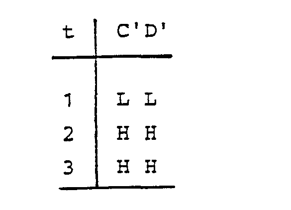
Zum Prüfzeitpunkt t1 sind beide Binärsignale C' und D' «L», zum Prüfzeitpunkt t2 sind beide Binärsignale C' und D' bereits « H " und zum Prüfzeitpunkt t3 sind wiederum beide Binärsignale C' und D' « H •. Da diese Zustandskombinationen der Binärsignale C' und D' gemäß der ersten « Wahrheitstabelle » unzulässig sind, wird von dem fehlersicheren Netzwerk F gemäß Figur 2 ein Alarm ausgelöst, bzw. die Bewegung der Maschinen-Bauteile 1 und 2 angehalten.At test time t1 both binary signals C 'and D' are "L", at test time t2 both binary signals C 'and D' are already "H" and at test time t3 both binary signals C 'and D' are "H" because these combinations of states of binary signals C 'and D' according to the first “truth table” are inadmissible, the fail-safe network F according to FIG. 2 triggers an alarm or the movement of
Der hier dargestellte Fehler « Betrieb mit zu niedriger Geschwindigkeit stellt im allgemeinen keinen kritischen Betriebszustand dar, jedoch ist die Überwachung hinsichtlich zu hoher Geschwindigkeit äußerst wichtig.The error shown here, “Operation at too low speed generally does not represent a critical operating state, but monitoring for too high speed is extremely important.
Ebenso ließe sich eine Überwachungseinrichtung nach der Erfindung so ausgestalten, daß die Verschiebegeschwindigkeit der Maschinen-Bauteile 1 und 2 in zwei Bereichen mit unterschiedlichen Toleranzen überwacht wird. Zu diesem Zweck wird der Fachmann drei oder vier Trigger mit unterschiedlichen Triggerschwellen vorsehen, so daß sich aus einem ersten Bereich der ersten Triggerschwellen lediglich ein Warnbereich bestimmen läßt, indem eine optische und/oder akustische Warnung erfolgt. Wird der durch diese ersten Trigger festgelegte Warnbereich jedoch über- bzw. unterschritten, so erfolgt eine Unterbrechung der Verschiebebewegung selbsttätig.A monitoring device according to the invention could also be designed in such a way that the displacement speed of the
Diese Anhaltebereich kann durch weitere Trigger mit anderen Triggerschwellen definiert sein.This stopping range can be defined by other triggers with other trigger thresholds.
Ebenso kann die selbsttätige Unterbrechung der Verschiebebewegung erfolgen, wenn eine bestimmte Verweilzeit im Warnbereich überschritten wird.Likewise, the automatic movement movement can be interrupted if a certain dwell time in the warning area is exceeded.
Claims (2)
Priority Applications (1)
| Application Number | Priority Date | Filing Date | Title |
|---|---|---|---|
| AT82102663T ATE27866T1 (en) | 1981-06-06 | 1982-03-30 | POSITIONING DEVICE. |
Applications Claiming Priority (2)
| Application Number | Priority Date | Filing Date | Title |
|---|---|---|---|
| DE19813122621 DE3122621A1 (en) | 1981-06-06 | 1981-06-06 | POSITIONING DEVICE |
| DE3122621 | 1981-06-06 |
Publications (3)
| Publication Number | Publication Date |
|---|---|
| EP0066682A2 EP0066682A2 (en) | 1982-12-15 |
| EP0066682A3 EP0066682A3 (en) | 1984-07-18 |
| EP0066682B1 true EP0066682B1 (en) | 1987-06-16 |
Family
ID=6134141
Family Applications (1)
| Application Number | Title | Priority Date | Filing Date |
|---|---|---|---|
| EP82102663A Expired EP0066682B1 (en) | 1981-06-06 | 1982-03-30 | Positioning device |
Country Status (5)
| Country | Link |
|---|---|
| US (1) | US4594538A (en) |
| EP (1) | EP0066682B1 (en) |
| JP (1) | JPS57203108A (en) |
| AT (1) | ATE27866T1 (en) |
| DE (1) | DE3122621A1 (en) |
Families Citing this family (14)
| Publication number | Priority date | Publication date | Assignee | Title |
|---|---|---|---|---|
| DE3331648A1 (en) * | 1983-09-02 | 1985-03-28 | Philips Patentverwaltung Gmbh, 2000 Hamburg | DEVICE FOR CONTROLLING A DRIVE FOR MOVING TOOLS, IN PARTICULAR MOLDED PARTS OF AN INJECTION MOLDING MACHINE |
| AT383900B (en) * | 1984-03-01 | 1987-09-10 | Bernhaider Wilhelm Ing | Electronic steering device for vehicles or the like |
| US4714005A (en) * | 1986-07-28 | 1987-12-22 | Vickers, Incorporated | Power transmission |
| JPH02146602A (en) * | 1988-08-11 | 1990-06-05 | Fanuc Ltd | Method for detecting/stopping collision of object to be driven by servo motor |
| SE467885B (en) * | 1990-12-20 | 1992-09-28 | Nomafa Ab | DEVICE FOR MONITORING OF AN ASYNCHRONIC MOTOR DRIVE PORT |
| JPH0680800U (en) * | 1993-04-26 | 1994-11-15 | 株式会社アイチコーポレーション | Work vehicle bodywork actuation device |
| US5524168A (en) * | 1995-03-03 | 1996-06-04 | Ford Motor Company | Method and apparatus for DC motor speed monitoring |
| DE19745490A1 (en) | 1997-10-15 | 1999-04-22 | Heidenhain Gmbh Dr Johannes | Electric motor operation monitoring method |
| DE19802728A1 (en) | 1998-01-24 | 1999-07-29 | Heidenhain Gmbh Dr Johannes | Machine parameter monitoring method for machine tool numerical control |
| WO1999042790A1 (en) | 1998-02-21 | 1999-08-26 | Dr. Johannes Heidenhain Gmbh | Method for operating a position measuring system and corresponding position measuring system |
| DE10018298B4 (en) * | 2000-04-13 | 2012-04-05 | Dr. Johannes Heidenhain Gmbh | Method and device for vibration detection in a position measuring device |
| DE102006020680A1 (en) * | 2006-04-27 | 2007-10-31 | Carl Zeiss Industrielle Messtechnik Gmbh | Selective activatable lasers triggering method for e.g. production of liquid crystal display, involves producing trigger signals for triggering lasers when current number of position pulses corresponds to number of pulses |
| JP2013192414A (en) * | 2012-03-15 | 2013-09-26 | Omron Corp | Drive control device |
| DE202019100128U1 (en) | 2019-01-11 | 2020-04-15 | Altendorf Gmbh | Woodworking machine and control device for a woodworking machine |
Family Cites Families (12)
| Publication number | Priority date | Publication date | Assignee | Title |
|---|---|---|---|---|
| BE795559A (en) * | 1972-02-16 | 1973-06-18 | Bizerba Werke Kraut Kg Wilh | ADDITIONAL DISTANCE MEASURING SYSTEM WITH ERROR PROTECTION |
| US3828742A (en) * | 1972-04-26 | 1974-08-13 | Caterpillar Tractor Co | Engine control system |
| US3778696A (en) * | 1972-06-23 | 1973-12-11 | Allen Bradley Co | Feedback fault indicate circuit |
| JPS5221670B2 (en) * | 1972-10-03 | 1977-06-11 | ||
| DE2258382A1 (en) * | 1972-11-29 | 1974-06-06 | Ibm Deutschland | REGULATING DEVICE FOR CONTROLLING THE MOVEMENT OF AN ADJUSTMENT ELEMENT |
| DE2337199C3 (en) * | 1973-07-21 | 1980-08-14 | Kiepe Elektrik Gmbh, 4000 Duesseldorf | Circuit arrangement for monitoring speeds |
| US3996454A (en) * | 1974-04-18 | 1976-12-07 | Actron Industries, Inc. | Servomechanism monitor for numerically controlled machine tools |
| DE2505585C3 (en) * | 1975-02-11 | 1978-06-08 | Dr. Johannes Heidenhain Gmbh, 8225 Traunreut | Length measuring device |
| DE2548717A1 (en) * | 1975-10-31 | 1977-05-05 | Hagenuk Neufeldt Kuhnke Gmbh | LIMITING DEVICE FOR REGULAR SIZE MEASURING DEVICES |
| US4083043A (en) * | 1976-02-18 | 1978-04-04 | Trw Inc. | High speed monolithic a/d converter utilizing strobe comparator |
| JPS5674708A (en) * | 1979-11-26 | 1981-06-20 | Toyoda Mach Works Ltd | Numerical control device |
| JPS622646Y2 (en) * | 1979-11-27 | 1987-01-22 |
-
1981
- 1981-06-06 DE DE19813122621 patent/DE3122621A1/en active Granted
-
1982
- 1982-03-30 AT AT82102663T patent/ATE27866T1/en not_active IP Right Cessation
- 1982-03-30 EP EP82102663A patent/EP0066682B1/en not_active Expired
- 1982-05-27 JP JP57088976A patent/JPS57203108A/en active Granted
-
1984
- 1984-09-14 US US06/650,984 patent/US4594538A/en not_active Expired - Fee Related
Also Published As
| Publication number | Publication date |
|---|---|
| US4594538A (en) | 1986-06-10 |
| EP0066682A3 (en) | 1984-07-18 |
| ATE27866T1 (en) | 1987-07-15 |
| DE3122621C2 (en) | 1987-04-09 |
| JPH0233162B2 (en) | 1990-07-25 |
| DE3122621A1 (en) | 1982-12-23 |
| EP0066682A2 (en) | 1982-12-15 |
| JPS57203108A (en) | 1982-12-13 |
Similar Documents
| Publication | Publication Date | Title |
|---|---|---|
| EP0066682B1 (en) | Positioning device | |
| DE3202339C2 (en) | Digital electrical length or angle measuring device | |
| EP0204897B1 (en) | Method and device for controlling the mark-to-space ratio of an electric signal | |
| DE2917290C2 (en) | A system for detecting a malfunction of a numerical control unit | |
| DE3424246C2 (en) | Method for monitoring a drive system | |
| DE2847779C3 (en) | Device for position detection in numerically controlled machine tools | |
| DE3306325C2 (en) | ||
| DE3417016C1 (en) | Method for determining the position and speed of objects | |
| DE3815530C2 (en) | ||
| EP1032519B1 (en) | Protective circuit for a controlling element and method for testing the control circuit of a controlling element | |
| DE3709129C2 (en) | ||
| DE2729408C2 (en) | Computer-guided numerical control arrangement for a machine tool | |
| EP0712679B1 (en) | Method and apparatus for discharge machining control | |
| DE3228665A1 (en) | CIRCUIT ARRANGEMENT FOR A CYCLICALLY ABSOLUTE POSITION MEASURING SYSTEM | |
| DE2400112A1 (en) | DIGITAL DATA RECORDING DEVICE | |
| DE4009749C2 (en) | ||
| DE19604968C2 (en) | Method for testing incremental measuring systems and testing device for carrying out the method | |
| DE3618072A1 (en) | Control system | |
| DE2442563A1 (en) | TIME INTERVAL MEASURING DEVICE | |
| EP0298183B1 (en) | Incremental position measuring system | |
| DE3539643C2 (en) | ||
| EP3788389B1 (en) | Redundant current-measuring arrangement with detection of interruptions of an electric circuit | |
| DE2842350C2 (en) | Circuit arrangement for monitoring clock pulse trains | |
| DE3011148A1 (en) | Position control of machine tool - using microprocessor to interpret position data to provide correct speed change down | |
| DE1449023C (en) | Test circuit for functional testing of position control devices |
Legal Events
| Date | Code | Title | Description |
|---|---|---|---|
| PUAI | Public reference made under article 153(3) epc to a published international application that has entered the european phase |
Free format text: ORIGINAL CODE: 0009012 |
|
| 17P | Request for examination filed |
Effective date: 19820403 |
|
| AK | Designated contracting states |
Designated state(s): AT CH FR GB IT LI NL SE |
|
| PUAL | Search report despatched |
Free format text: ORIGINAL CODE: 0009013 |
|
| AK | Designated contracting states |
Designated state(s): AT CH FR GB IT LI NL SE |
|
| ITF | It: translation for a ep patent filed |
Owner name: VETTOR GALLETTI DI SAN CATALDO |
|
| GRAA | (expected) grant |
Free format text: ORIGINAL CODE: 0009210 |
|
| AK | Designated contracting states |
Kind code of ref document: B1 Designated state(s): AT CH FR GB IT LI NL SE |
|
| REF | Corresponds to: |
Ref document number: 27866 Country of ref document: AT Date of ref document: 19870715 Kind code of ref document: T |
|
| ET | Fr: translation filed | ||
| PLBE | No opposition filed within time limit |
Free format text: ORIGINAL CODE: 0009261 |
|
| STAA | Information on the status of an ep patent application or granted ep patent |
Free format text: STATUS: NO OPPOSITION FILED WITHIN TIME LIMIT |
|
| 26N | No opposition filed | ||
| PGFP | Annual fee paid to national office [announced via postgrant information from national office to epo] |
Ref country code: GB Payment date: 19910218 Year of fee payment: 10 |
|
| PGFP | Annual fee paid to national office [announced via postgrant information from national office to epo] |
Ref country code: CH Payment date: 19910219 Year of fee payment: 10 |
|
| PGFP | Annual fee paid to national office [announced via postgrant information from national office to epo] |
Ref country code: FR Payment date: 19910220 Year of fee payment: 10 |
|
| PGFP | Annual fee paid to national office [announced via postgrant information from national office to epo] |
Ref country code: AT Payment date: 19910226 Year of fee payment: 10 |
|
| PGFP | Annual fee paid to national office [announced via postgrant information from national office to epo] |
Ref country code: SE Payment date: 19910311 Year of fee payment: 10 |
|
| ITTA | It: last paid annual fee | ||
| PGFP | Annual fee paid to national office [announced via postgrant information from national office to epo] |
Ref country code: NL Payment date: 19910331 Year of fee payment: 10 |
|
| PG25 | Lapsed in a contracting state [announced via postgrant information from national office to epo] |
Ref country code: AT Effective date: 19920330 Ref country code: GB Effective date: 19920330 |
|
| PG25 | Lapsed in a contracting state [announced via postgrant information from national office to epo] |
Ref country code: CH Effective date: 19920331 Ref country code: SE Effective date: 19920331 Ref country code: LI Effective date: 19920331 |
|
| PG25 | Lapsed in a contracting state [announced via postgrant information from national office to epo] |
Ref country code: NL Effective date: 19921001 |
|
| NLV4 | Nl: lapsed or anulled due to non-payment of the annual fee | ||
| GBPC | Gb: european patent ceased through non-payment of renewal fee | ||
| PG25 | Lapsed in a contracting state [announced via postgrant information from national office to epo] |
Ref country code: FR Effective date: 19921130 |
|
| REG | Reference to a national code |
Ref country code: CH Ref legal event code: PL |
|
| REG | Reference to a national code |
Ref country code: FR Ref legal event code: ST |
|
| PGFP | Annual fee paid to national office [announced via postgrant information from national office to epo] |
Ref country code: LU Payment date: 19930527 Year of fee payment: 15 |
|
| EPTA | Lu: last paid annual fee | ||
| EUG | Se: european patent has lapsed |
Ref document number: 82102663.0 Effective date: 19921005 |