EP0451446A1 - Device for detecting the driving of a slope - Google Patents
Device for detecting the driving of a slope Download PDFInfo
- Publication number
- EP0451446A1 EP0451446A1 EP91101185A EP91101185A EP0451446A1 EP 0451446 A1 EP0451446 A1 EP 0451446A1 EP 91101185 A EP91101185 A EP 91101185A EP 91101185 A EP91101185 A EP 91101185A EP 0451446 A1 EP0451446 A1 EP 0451446A1
- Authority
- EP
- European Patent Office
- Prior art keywords
- vehicle
- load
- nha
- rear axle
- axle load
- Prior art date
- Legal status (The legal status is an assumption and is not a legal conclusion. Google has not performed a legal analysis and makes no representation as to the accuracy of the status listed.)
- Granted
Links
Images
Classifications
-
- G—PHYSICS
- G01—MEASURING; TESTING
- G01C—MEASURING DISTANCES, LEVELS OR BEARINGS; SURVEYING; NAVIGATION; GYROSCOPIC INSTRUMENTS; PHOTOGRAMMETRY OR VIDEOGRAMMETRY
- G01C9/00—Measuring inclination, e.g. by clinometers, by levels
Definitions
- the invention relates to a device for mountain trip detection according to the preamble of claim 1.
- Such a device (slope determination) for vehicles is known from DE-A-33 347 19.
- a special inclination sensor is not required here.
- different engine and vehicle-specific data are necessary, e.g. B. a motor characteristic field, which are only available for a few applications.
- a current assessment of whether a vehicle, in particular a commercial vehicle (truck or bus) is currently on an uphill or downhill slope is important as a criterion for various electronic subsystems in the vehicle, for example for a drawbar force control. This controls the brakes in the towing vehicle and in the trailer so that the drawbar force does not exceed a certain value. This prevents the trailer from being pushed open.
- a drawbar force control This controls the brakes in the towing vehicle and in the trailer so that the drawbar force does not exceed a certain value. This prevents the trailer from being pushed open.
- the system mentioned can thus be improved without significant additional costs or malfunctions can be prevented.
- the object of the invention is to provide an arrangement which reliably detects an ascent or descent with simple means.
- the device according to the invention uses the effect of the axle load shift when driving up an incline or a slope compared to driving in a plane, which has not been evaluated for this purpose so far. This increases the axle load on the rear axle when negotiating an incline, while reducing the axle load when negotiating a slope. This effect essentially depends on the height of the center of gravity and the load on the vehicle.
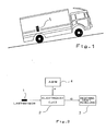
- a vehicle is shown schematically when negotiating an incline. As you can see, this puts a greater load on the rear axle while relieving the front axle (exaggerated).
- the load or deflection of the rear axle is sensed by a load sensor (1).
- the load sensor is attached at a suitable point, for example at the load points of the suspension. It can also sense the deflection of the rear axle. If the vehicle has air suspension, the pressure in the bellows can also be evaluated. Instead of using a force sensor or load sensor, the deflection of the vehicle can also be evaluated using a displacement sensor.
- the output value of the load sensor (1) is fed to electronics (microcomputers) (2).
- the value of the vehicle acceleration or deceleration (a) is made available by a device (4).
- This value can e.g. B. from an anti-lock braking system (ABS), where it is generally present.
- ABS anti-lock braking system
- the anti-lock braking system determines the vehicle's acceleration by evaluating the wheel speeds and is therefore independent of the incline traveled.
- the anti-lock braking system also contains at least one microcomputer. Its functioning is known to the person skilled in the art (DE-A-28 44 279).
- the microcomputer in the electronics (2) is programmed so that it can evaluate the formulas listed below.
- the type TMS 7742 from Texas Instruments can be used, for example.
- the electronics (2) determine from the supplied data whether there is an ascent or descent.
- the electronics (2) pass the decision as to whether the journey is uphill or downhill or also directly the value of the road gradient ⁇ to other electronics, for example a drawbar force control (3) for further use.
- the rear axle load F NHAE is expediently determined in such a way that the current value F NHA detected by the rear axle load sensor is stored at certain time or distance intervals and all the detected values are averaged by software using a suitable, known method. However, such a method is not the subject of this invention.
- the rear axle load in the level F NHAE can also be recorded by storing the current value when driving on the level by actuating a switch by the driver.
- the exact angle of inclination ⁇ of the road traveled can also be used with the help of approximately already known data such as B. wheelbase, center of gravity, vehicle weight u. a. be determined.
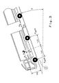
- FIG. 3 shows schematically a truck traveling downhill and the forces acting on it.
- the electronics (2) can be entered as estimates.
- the vehicle mass m can be approximately determined using the existing load sensor (1). If the drawbar force F K is sensed, this is also known, but could otherwise also be assumed with a constant value or possibly neglected.
- the road gradient ⁇ determined in this way is sufficiently precise for most applications.
Abstract
Description
Die Erfindung betrifft eine Einrichtung zur Bergfahrt-Erkennung gemäß dem Oberbegriff des Patentanspruchs 1.The invention relates to a device for mountain trip detection according to the preamble of
Eine solche Einrichtung (Steigungsermittlung) für Fahrzeuge ist aus der DE-A-33 347 19 bekannt. Hier ist ein besonderer Neigungssensor nicht erforderlich. Es sind jedoch verschiedene motor- und fahrzeugspezifische Daten notwendig, z. B. ein Motorkennlinienfeld, welche nur für wenige Anwendungsfälle zur Verfügung stehen.Such a device (slope determination) for vehicles is known from DE-A-33 347 19. A special inclination sensor is not required here. However, different engine and vehicle-specific data are necessary, e.g. B. a motor characteristic field, which are only available for a few applications.
Eine momentane Bewertung, ob sich ein Fahrzeug, insbesondere ein Nutzfahrzeug (Lkw oder Bus) gerade auf einer Steigung oder auf einem Gefälle befindet, ist wichtig als Kriterium für verschiedene elektronische Untersysteme im Fahrzeug, beispielsweise für eine Deichselkraftregelung. Bei dieser werden die Bremsen im Zugfahrzeug und im Hänger so geregelt, daß die Deichselkraft einen bestimmten Wert nicht überschreitet. Hierdurch wird ein Aufschieben des Hängers verhindert.A current assessment of whether a vehicle, in particular a commercial vehicle (truck or bus) is currently on an uphill or downhill slope is important as a criterion for various electronic subsystems in the vehicle, for example for a drawbar force control. This controls the brakes in the towing vehicle and in the trailer so that the drawbar force does not exceed a certain value. This prevents the trailer from being pushed open.
Das genannte System kann damit ohne wesentliche Mehrkosten verbessert werden bzw. es können Fehlfunktionen verhindert werden.The system mentioned can thus be improved without significant additional costs or malfunctions can be prevented.
Aufgabe der Erfindung ist es, eine Anordnung anzugeben, welche eine Bergfahrt oder eine Talfahrt zuverlässig und mit einfachen Mitteln erkennt.The object of the invention is to provide an arrangement which reliably detects an ascent or descent with simple means.
Diese Aufgabe wird durch die im Patentanspruch 1 enthaltene Erfindung gelöst. Die Unteransprüche enthalten zweckmäßige Weiterbildungen der Erfindung.This object is achieved by the invention contained in
Die erfindungsgemäße Einrichtung benutzt den bisher zu diesem Zweck nicht ausgewerteten Effekt der Achslastverlagerung beim Befahren einer Steigung oder eines Gefälles gegenüber der Fahrt in einer Ebene. So erhöht sich die Achslast der Hinterachse beim Befahren einer Steigung, während sich die Achslast beim Befahren eines Gefälles verringert. Dieser Effekt ist im wesentlichen abhängig von der Höhe des Schwerpunktes und der Beladung des Fahrzeugs.The device according to the invention uses the effect of the axle load shift when driving up an incline or a slope compared to driving in a plane, which has not been evaluated for this purpose so far. This increases the axle load on the rear axle when negotiating an incline, while reducing the axle load when negotiating a slope. This effect essentially depends on the height of the center of gravity and the load on the vehicle.
Da bekanntlich auch eine Fahrzeugbeschleunigung oder -verzögerung zu den gleichen Effekten einer Achslastverlagerung führt, ist es zweckmäßig, gleichzeitig eine Erfassung der Fahrzeugbeschleunigung durchzuführen, und deren Höhe entweder bei der Bergfahrterkennung zu berücksichtigen oder die Achslastverlagerung nur während einer unbeschleunigten Fahrt auszuwerten.Since, as is well known, vehicle acceleration or deceleration also leads to the same effects of an axle load shift, it is advisable to simultaneously record the vehicle acceleration and either take the amount into account when detecting an ascent or to evaluate the axle load shift only during an unaccelerated journey.
Gemäß einer Weiterbildung der Erfindung ist es auch möglich, die Straßensteigung direkt zu berechnen.According to a development of the invention, it is also possible to calculate the road gradient directly.
Die Erfindung wird im folgenden anhand einer Zeichnung näher erläutert. Diese zeigt in schematischer Darstellung in
Figur 1 ein Fahrzeug beim Befahren einer Steigung, inFigur 2 ein Blockschaltbild der Elektronik, und inFigur 3 einen Lastzug in einem Gefälle.
- 1 shows a vehicle when negotiating an incline, in
- Figure 2 is a block diagram of the electronics, and in
- Figure 3 shows a road train on a slope.
In Figur 1 ist schematisch ein Fahrzeug beim Befahren einer Steigung dargestellt. Wie man erkennt, wird hierdurch die Hinterachse stärker belastet, während die Vorderachse entlastet wird (übertrieben dargestellt). Die stärkere Belastung bzw. Einfederung der Hinterachse wird durch einen Lastsensor (1) sensiert. Der Lastsensor ist an geeigneter Stelle, beispielsweise an den Belastungspunkten der Federung, angebracht. Er kann auch die Durchbiegung der Hinterachse sensieren. Falls das Fahrzeug luftgefedert ist, kann auch der Druck in den Federbälgen ausgewertet werden. Anstatt einen Kraftsensor bzw. Lastsensor zu verwenden, kann man auch die Einfederung des Fahrzeugs mittels eines Wegsensors auswerten.In Figure 1, a vehicle is shown schematically when negotiating an incline. As you can see, this puts a greater load on the rear axle while relieving the front axle (exaggerated). The load or deflection of the rear axle is sensed by a load sensor (1). The load sensor is attached at a suitable point, for example at the load points of the suspension. It can also sense the deflection of the rear axle. If the vehicle has air suspension, the pressure in the bellows can also be evaluated. Instead of using a force sensor or load sensor, the deflection of the vehicle can also be evaluated using a displacement sensor.
Gemäß der Figur 2 wird der Ausgangswert des Lastsensors (1) einer Elektronik (Mikrocomputer) (2) zugeleitet. Außerdem wird noch der Wert der Fahrzeugbeschleunigung bzw. -verzögerung (a) von einer Einrichtung (4) zur Verfügung gestellt. Dieser Wert kann z. B. aus einem Antiblockiersystem (ABS) entnommen werden, wo dieser im allgemeinen vorliegt. Das Antiblockiersystem bestimmt die Fahrzeugbeschleunigung durch Auswertung der Radgeschwindigkeiten und somit unabhängig von der befahrenen Steigung.According to FIG. 2, the output value of the load sensor (1) is fed to electronics (microcomputers) (2). In addition, the value of the vehicle acceleration or deceleration (a) is made available by a device (4). This value can e.g. B. from an anti-lock braking system (ABS), where it is generally present. The anti-lock braking system determines the vehicle's acceleration by evaluating the wheel speeds and is therefore independent of the incline traveled.
Das Antiblockiersystem enthält ebenfalls mindestens einen Mikrocomputer. Seine Funktionsweise ist dem Fachmann bekannt (DE-A-28 44 279).The anti-lock braking system also contains at least one microcomputer. Its functioning is known to the person skilled in the art (DE-A-28 44 279).
Der Mikrocomputer in der Elektronik (2) ist so programmiert, daß er die weiter unten aufgeführten Formeln auswerten kann. Als Typ kann beispielsweise der TMS 7742 der Firma Texas Instruments verwendet werden.The microcomputer in the electronics (2) is programmed so that it can evaluate the formulas listed below. The type TMS 7742 from Texas Instruments can be used, for example.
Die Elektronik (2) bestimmt aus den zugeleiteten Daten, ob eine Berg- oder Talfahrt vorliegt.The electronics (2) determine from the supplied data whether there is an ascent or descent.
Auf Bergfahrt wird beispielsweise dann erkannt, wenn gilt:
![]()
When driving uphill, for example, it is recognized if:
![]()
In dieser Formel bedeuten:
- FNHAE
- = Wert der Hinterachslast in der Ebene
- FNHA
- = aktueller Wert der Hinterachslast
- ΔFNHA
- = Differenz zwischen dem aktuellen Wert der Hinterachslast und der Hinterachslast in der Ebene, ab der auf Bergfahrt erkannt werden soll
- aF
- = Fahrzeugbeschleunigung relativ zur Fahrbahn
- aFmin
- = Schwellenwert der Fahrzeugverzögerung, unterhalb welchen aF = 0 angenommen wird.
- F NHAE
- = Value of the rear axle load in the plane
- F NHA
- = current value of the rear axle load
- ΔF NHA
- = Difference between the current value of the rear axle load and the rear axle load in the plane from which to detect when driving uphill
- a F
- = Vehicle acceleration relative to the road
- a Fmin
- = Threshold value of the vehicle deceleration, below which a F = 0 is assumed.
Die Elektronik (2) gibt die Entscheidung, ob Berg- oder Talfahrt vorliegt oder auch direkt den Wert der Straßensteigung α, an eine weitere Elektronik, beispielsweise eine Deichselkraftregelung (3) zur weiteren Verwendung ab.The electronics (2) pass the decision as to whether the journey is uphill or downhill or also directly the value of the road gradient α to other electronics, for example a drawbar force control (3) for further use.
Die Hinterachslast FNHAE wird zweckmäßig so ermittelt, daß in bestimmten Zeit- oder Wegabständen der vom Hinterachs-Lastsensor erfaßte aktuelle Wert FNHA gespeichert und alle erfaßten Werte durch ein geeignetes, bekanntes Verfahren softwaremäßig gemittelt werden. Ein solches Verfahren ist aber nicht Gegenstand dieser Erfindung.The rear axle load F NHAE is expediently determined in such a way that the current value F NHA detected by the rear axle load sensor is stored at certain time or distance intervals and all the detected values are averaged by software using a suitable, known method. However, such a method is not the subject of this invention.
Da die Hinterachslast infolge der Fahrbahnunebenheiten schwankt, empfiehlt sich eine Filterung des Ausgangssignales des Hinterachs-Lastsensors (4).Since the rear axle load fluctuates due to the bumps in the road, filtering the output signal of the rear axle load sensor (4) is recommended.
Die Erfassung der Hinterachslast in der Ebene FNHAE kann auch durch Abspeichern des momentanen Wertes bei Fahrt in der Ebene durch eine Schalterbetätigung durch den Fahrer erfolgen.The rear axle load in the level F NHAE can also be recorded by storing the current value when driving on the level by actuating a switch by the driver.
In Weiterbildung der Erfindung kann auch der genaue Steigungswinkel α der befahrenen Straße mit Hilfe von näherungsweise bereits bekannten Daten wie z. B. Radstand, Schwerpunktlage, Fahrzeugmasse u. a. ermittelt werden.In a further development of the invention, the exact angle of inclination α of the road traveled can also be used with the help of approximately already known data such as B. wheelbase, center of gravity, vehicle weight u. a. be determined.
In der Figur 3 ist schematisch ein bergab fahrender Lastzug sowie die auf diesen einwirkenden Kräfte dargestellt.FIG. 3 shows schematically a truck traveling downhill and the forces acting on it.
- αα
- = Straßensteigung= Road gradient
- mm
- = Fahrzeugmasse= Vehicle mass
- hH
- = Fahrzeugverzögerung= Vehicle deceleration
- gG
- = Erdbeschleunigung= Acceleration due to gravity
- hs h s
- = Fahrzeugschwerpunkthöhe= Vehicle center of gravity
- lv l v
- = Abstand des Fahrzeugschwerpunktes von der Vorderachse= Distance of the vehicle's center of gravity from the front axle
- lh l h
- = Abstand des Fahrzeugschwerpunktes von der Hinterachse= Distance of the vehicle's center of gravity from the rear axle
- FK F K
- = Kuppelkraft (Deichselkraft)= Coupling force (drawbar force)
- hK h K
- = Höhe der Anhängerkupplung= Height of the towbar
- FNHA F NHA
- = Hinterachslast= Rear axle load
Die Kräfte FNHA und FK sind in Newton [kgm/s²] anzugeben.The forces F NHA and F K must be given in Newtons [kgm / s²].
Bildet man nun die Summe der Momente um den Punkt A, so ergibt sich
![]()
![]()
If one now forms the sum of the moments around point A, the result is
![]()
![]()
Für kleine Winkel gilt:
![]()
For small angles:
![]()
Daraus folgt:
![]()
It follows:
![]()
Hieraus folgt für die Straßensteigung α
Nicht direkt erfaßbare Parameter, die in der Gleichung für die Straßensteigung α vorhanden sind, wie z. B. die Höhe des Fahrzeugschwerpunktes hs sowie die übrigen Abmessungen, können der Elektronik (2) als Schätzwerte eingegeben werden. Die Fahrzeugmasse m kann über den vorhandenen Lastsensor (1) näherungsweise ermittelt werden. Wird die Deichselkraft FK sensiert, so ist auch diese bekannt, könnte aber sonst auch mit einem konstanten Wert angenommen oder eventuell auch vernachlässigt werden. Die hiermit bestimmte Straßensteigung α ist für die meisten Anwendungsfälle ausreichend genau.From this follows α for the road gradient
Parameters that are not directly detectable and are present in the equation for the road gradient α, such as e.g. B. the height of the vehicle center of gravity h s and the other dimensions, the electronics (2) can be entered as estimates. The vehicle mass m can be approximately determined using the existing load sensor (1). If the drawbar force F K is sensed, this is also known, but could otherwise also be assumed with a constant value or possibly neglected. The road gradient α determined in this way is sufficiently precise for most applications.
Claims (6)
gekennzeichnet durch einen Sensor (1) für die Achslast der Hinterachse und/oder der Vorderachse und eine Elektronik (2), welcher die Signale des Sensors (1) und der Einrichtung (4) zugeleitet werden, und welche hieraus die durch eine Berg- oder Talfahrt verursachte Achslastverlagerung erkennt.Device for mountain trip detection, in particular for commercial vehicles with at least two axles, and with a device (4) for measuring vehicle acceleration,
characterized by a sensor (1) for the axle load of the rear axle and / or the front axle and an electronic system (2) to which the signals from the sensor (1) and the device (4) are fed, and from which the signals from a mountain or Detection of the axle load caused by the downward movement is recognized.
worin bedeuten:
in which mean:

Applications Claiming Priority (2)
| Application Number | Priority Date | Filing Date | Title |
|---|---|---|---|
| DE4010073 | 1990-03-29 | ||
| DE4010073A DE4010073A1 (en) | 1990-03-29 | 1990-03-29 | MOUNTAIN DETECTION DEVICE |
Publications (2)
| Publication Number | Publication Date |
|---|---|
| EP0451446A1 true EP0451446A1 (en) | 1991-10-16 |
| EP0451446B1 EP0451446B1 (en) | 1994-06-01 |
Family
ID=6403317
Family Applications (1)
| Application Number | Title | Priority Date | Filing Date |
|---|---|---|---|
| EP91101185A Expired - Lifetime EP0451446B1 (en) | 1990-03-29 | 1991-01-30 | Device for detecting the driving of a slope |
Country Status (5)
| Country | Link |
|---|---|
| US (1) | US5187977A (en) |
| EP (1) | EP0451446B1 (en) |
| JP (1) | JP3116310B2 (en) |
| AT (1) | ATE106549T1 (en) |
| DE (2) | DE4010073A1 (en) |
Cited By (1)
| Publication number | Priority date | Publication date | Assignee | Title |
|---|---|---|---|---|
| WO2010139493A1 (en) * | 2009-06-03 | 2010-12-09 | Zf Friedrichshafen Ag | Method for calibrating a slope sensor |
Families Citing this family (23)
| Publication number | Priority date | Publication date | Assignee | Title |
|---|---|---|---|---|
| EP0534892B1 (en) * | 1991-09-27 | 1996-05-22 | Nessim Igal Levy | Position-locating method |
| US5351540A (en) * | 1992-09-30 | 1994-10-04 | Eaton Corporation | Grade angle and acceleration sensor |
| DE4443522C2 (en) * | 1994-12-07 | 1999-11-25 | Daimler Chrysler Ag | Procedure for determining the slope of the road |
| DE19538616C2 (en) * | 1995-10-17 | 2003-11-27 | Continental Teves Ag & Co Ohg | Device for detecting a vehicle inclination and / or a vehicle acceleration |
| US6115668A (en) * | 1997-03-07 | 2000-09-05 | Pioneer Electronic Corporation | Navigation apparatus for detecting a present position of a moveable body |
| DE19728867A1 (en) * | 1997-07-05 | 1999-01-07 | Bosch Gmbh Robert | Method of weighing motor vehicle, especially commercial vehicle |
| US6625535B2 (en) | 2001-08-17 | 2003-09-23 | General Motors Corporation | Adaptive powertrain braking control with grade, mass, and brake temperature |
| JP4597960B2 (en) * | 2003-03-25 | 2010-12-15 | ソシエテ ド テクノロジー ミシュラン | Method of attaching tire to construction machine and tire |
| KR100575933B1 (en) * | 2003-12-01 | 2006-05-02 | 삼성전자주식회사 | Method and apparatus for measuring speed of land vehicle using accelerometer and route guidance information data |
| JP4635530B2 (en) * | 2004-09-14 | 2011-02-23 | トヨタ自動車株式会社 | Control device for vehicle drive device |
| JP4314250B2 (en) * | 2006-05-23 | 2009-08-12 | トヨタ自動車株式会社 | Road surface determination device for vehicles |
| US7757406B2 (en) * | 2007-05-29 | 2010-07-20 | Sepehr Khashaei | Vehicle travel grade indicator (VTGI) |
| US8028433B1 (en) * | 2010-10-14 | 2011-10-04 | Holland Carl A | Method and device for measuring the inclination of a roadway |
| US9061686B2 (en) * | 2013-10-29 | 2015-06-23 | Ford Global Technologies, Llc | Road grade estimation for a trailered vehicle |
| US9744970B2 (en) * | 2014-07-14 | 2017-08-29 | Ford Global Technologies, Llc | Estimating a trailer road grade |
| CN107291104A (en) | 2014-07-30 | 2017-10-24 | 深圳市大疆创新科技有限公司 | Target tracking system and method |
| KR101601104B1 (en) * | 2014-09-22 | 2016-03-08 | 현대자동차주식회사 | Appratus and method of road slope estimating by using gravity sensor |
| CN105116167A (en) * | 2015-09-10 | 2015-12-02 | 深圳威易森科技有限公司 | Acceleration determination method for motor vehicle running on slope plane |
| DE102015115851A1 (en) | 2015-09-21 | 2017-03-23 | Knorr-Bremse Systeme für Nutzfahrzeuge GmbH | Method for operating a team |
| US9758167B1 (en) | 2016-03-08 | 2017-09-12 | Gkn Driveline North America, Inc. | Hill detection and grade percent estimation logic for an all-wheel drive system |
| EP3432109B1 (en) * | 2017-07-17 | 2021-03-17 | AGCO International GmbH | System and method for self-tuning of an agricultural tractor and implement |
| CN110409264B (en) * | 2019-07-29 | 2021-05-07 | 中煤第三建设(集团)有限责任公司 | Equipment for detecting road surface inclination angle by paving road bridge |
| TWI790887B (en) * | 2022-01-10 | 2023-01-21 | 盈利達科技有限公司 | Calculation method and device of driving force acceleration |
Citations (2)
| Publication number | Priority date | Publication date | Assignee | Title |
|---|---|---|---|---|
| DE3334719A1 (en) * | 1983-09-26 | 1985-04-04 | Wabco Westinghouse Fahrzeugbremsen GmbH, 3000 Hannover | DEVICE FOR DETERMINING THE RAILWAY SLOPE |
| WO1986000129A1 (en) * | 1984-06-16 | 1986-01-03 | Robert Bosch Gmbh | Process for correcting angular errors in an electronic compass in vehicles |
Family Cites Families (14)
| Publication number | Priority date | Publication date | Assignee | Title |
|---|---|---|---|---|
| US3266302A (en) * | 1965-06-09 | 1966-08-16 | Gen Motors Corp | Displacement measuring means |
| GB1251832A (en) * | 1968-01-15 | 1971-11-03 | ||
| US3632176A (en) * | 1969-12-09 | 1972-01-04 | Gen Motors Corp | Vehicle wheel slip control system and road grade sensor therefor and method of controlling wheel slip |
| DE2435115C2 (en) * | 1974-07-22 | 1983-12-22 | Daimler-Benz Ag, 7000 Stuttgart | Device for regulating the braking force on the wheels of motor vehicle combinations |
| US4422322A (en) * | 1982-04-27 | 1983-12-27 | Spangler Elson B | Method and system for measurement of road profile |
| US4473319A (en) * | 1982-04-27 | 1984-09-25 | Surface Dynamics Inc. | Controlled resurfacing of roads and the like |
| US4543724A (en) * | 1982-11-24 | 1985-10-01 | Citizen Watch Co., Ltd. | Measuring device for oblique angle |
| DE3302169A1 (en) * | 1983-01-24 | 1984-07-26 | Hans 2000 Hamburg Hoppe | Device for measuring the trim in ships |
| JPS632108U (en) * | 1986-06-23 | 1988-01-08 | ||
| JPS6378018A (en) * | 1986-09-22 | 1988-04-08 | Sanshin Ind Co Ltd | Detecting device for trim of marine vessel |
| US4741207A (en) * | 1986-12-29 | 1988-05-03 | Spangler Elson B | Method and system for measurement of road profile |
| FR2626363B1 (en) * | 1988-01-27 | 1993-02-19 | Telemecanique Electrique | DEVICE FOR DETECTING AT LEAST ONE VARIABLE RELATING TO THE MOVEMENT OF A MOBILE |
| JP2519084B2 (en) * | 1988-04-19 | 1996-07-31 | 富士通テン株式会社 | Vehicle acceleration detection device |
| US5065618A (en) * | 1990-11-14 | 1991-11-19 | Hodges Transportation Inc. | Method and apparatus for determining terrain surface profiles |
-
1990
- 1990-03-29 DE DE4010073A patent/DE4010073A1/en not_active Withdrawn
-
1991
- 1991-01-30 EP EP91101185A patent/EP0451446B1/en not_active Expired - Lifetime
- 1991-01-30 DE DE59101751T patent/DE59101751D1/en not_active Expired - Lifetime
- 1991-01-30 AT AT91101185T patent/ATE106549T1/en not_active IP Right Cessation
- 1991-03-15 JP JP03128826A patent/JP3116310B2/en not_active Expired - Fee Related
- 1991-03-28 US US07/676,892 patent/US5187977A/en not_active Expired - Lifetime
Patent Citations (2)
| Publication number | Priority date | Publication date | Assignee | Title |
|---|---|---|---|---|
| DE3334719A1 (en) * | 1983-09-26 | 1985-04-04 | Wabco Westinghouse Fahrzeugbremsen GmbH, 3000 Hannover | DEVICE FOR DETERMINING THE RAILWAY SLOPE |
| WO1986000129A1 (en) * | 1984-06-16 | 1986-01-03 | Robert Bosch Gmbh | Process for correcting angular errors in an electronic compass in vehicles |
Non-Patent Citations (1)
| Title |
|---|
| PATENT ABSTRACTS OF JAPAN, Band 009, Nr. 194 (M-403), 10. August 1985; & JP-A-60 060 047 (CHIYUUOU HATSUJIYOU) 06-04-1985 * |
Cited By (4)
| Publication number | Priority date | Publication date | Assignee | Title |
|---|---|---|---|---|
| WO2010139493A1 (en) * | 2009-06-03 | 2010-12-09 | Zf Friedrichshafen Ag | Method for calibrating a slope sensor |
| CN102458955A (en) * | 2009-06-03 | 2012-05-16 | Zf腓德烈斯哈芬股份公司 | Method for calibrating a slope sensor |
| US8386123B2 (en) | 2009-06-03 | 2013-02-26 | Zf Friedrichshafen Ag | Method for calibrating a slope sensor |
| CN102458955B (en) * | 2009-06-03 | 2014-09-10 | Zf腓德烈斯哈芬股份公司 | Method for calibrating a slope sensor |
Also Published As
| Publication number | Publication date |
|---|---|
| US5187977A (en) | 1993-02-23 |
| DE59101751D1 (en) | 1994-07-07 |
| JP3116310B2 (en) | 2000-12-11 |
| ATE106549T1 (en) | 1994-06-15 |
| EP0451446B1 (en) | 1994-06-01 |
| DE4010073A1 (en) | 1991-10-02 |
| JPH04230804A (en) | 1992-08-19 |
Similar Documents
| Publication | Publication Date | Title |
|---|---|---|
| EP0451446B1 (en) | Device for detecting the driving of a slope | |
| EP1430276B1 (en) | Method for determining the mass of a motor vehicle while taking into account different driving situations | |
| EP0918003B1 (en) | Procedure and device for determining a parameter related to the height of the centre of gravity of a vehicle | |
| EP1021326B1 (en) | Method for determining vehicle status variables | |
| DE10144299B4 (en) | Method for driving state stabilization of a commercial vehicle association | |
| DE19549083B4 (en) | security system | |
| DE4412430C1 (en) | Adjustment of distribution of brake force between tractor and trailer | |
| DE19918525B4 (en) | Device for estimating the center of gravity of vehicles | |
| EP1298020B1 (en) | Vehicle mass determination method taking into account different driving situations | |
| DE19728867A1 (en) | Method of weighing motor vehicle, especially commercial vehicle | |
| WO1999026812A1 (en) | Method and device for detecting motor vehicle tilt | |
| WO1996011128A1 (en) | System for controlling the running stability of a motor vehicle | |
| EP1104732A2 (en) | Procedure for preventing a vehicle overturning | |
| EP0947817B1 (en) | Measuring apparatus for vehicle diagnostic | |
| DE10338879A1 (en) | Method for estimating a lateral acceleration of a vehicle | |
| DE10160059A1 (en) | Accurate determination of motor vehicle loading from measurements of the normal force component acting between a wheel contact surface and the driving surface | |
| EP0812747A2 (en) | Device and method for locking and release of pressure actuated vehicle brakes as a starting aid on an inclined roadway | |
| DE102017123364A1 (en) | Method and device for headlight range adjustment of a headlight | |
| DE102014200987A1 (en) | Method for determining the position of the center of gravity of a vehicle | |
| EP1319535B1 (en) | Method for the on board determination of the existing rolling moment and/or the actual height of the centre of gravity of a vehicle | |
| DE4446358C1 (en) | rake force distribution regulation system for tractor/trailer vehicle | |
| DE602004011483T2 (en) | ARRANGEMENT AND METHOD FOR ESTIMATING THE HEIGHT OF THE HEAVY DUTY OF A VEHICLE | |
| EP1536986B1 (en) | Device for recognizing a vehicle overturn | |
| WO1989005248A1 (en) | Safety device for multi-axle vehicles | |
| EP1571058B1 (en) | Braking method for a vehicle |
Legal Events
| Date | Code | Title | Description |
|---|---|---|---|
| PUAI | Public reference made under article 153(3) epc to a published international application that has entered the european phase |
Free format text: ORIGINAL CODE: 0009012 |
|
| AK | Designated contracting states |
Kind code of ref document: A1 Designated state(s): AT DE FR GB IT NL SE |
|
| 17P | Request for examination filed |
Effective date: 19910930 |
|
| RAP1 | Party data changed (applicant data changed or rights of an application transferred) |
Owner name: WABCO VERMOEGENSVERWALTUNGS-GMBH |
|
| 17Q | First examination report despatched |
Effective date: 19930519 |
|
| GRAA | (expected) grant |
Free format text: ORIGINAL CODE: 0009210 |
|
| AK | Designated contracting states |
Kind code of ref document: B1 Designated state(s): AT DE FR GB IT NL SE |
|
| REF | Corresponds to: |
Ref document number: 106549 Country of ref document: AT Date of ref document: 19940615 Kind code of ref document: T |
|
| ITF | It: translation for a ep patent filed |
Owner name: JACOBACCI CASETTA & PERANI S.P.A. |
|
| REF | Corresponds to: |
Ref document number: 59101751 Country of ref document: DE Date of ref document: 19940707 |
|
| ET | Fr: translation filed | ||
| GBT | Gb: translation of ep patent filed (gb section 77(6)(a)/1977) |
Effective date: 19940912 |
|
| EAL | Se: european patent in force in sweden |
Ref document number: 91101185.6 |
|
| PLBE | No opposition filed within time limit |
Free format text: ORIGINAL CODE: 0009261 |
|
| STAA | Information on the status of an ep patent application or granted ep patent |
Free format text: STATUS: NO OPPOSITION FILED WITHIN TIME LIMIT |
|
| 26N | No opposition filed | ||
| PGFP | Annual fee paid to national office [announced via postgrant information from national office to epo] |
Ref country code: AT Payment date: 19971125 Year of fee payment: 8 |
|
| PGFP | Annual fee paid to national office [announced via postgrant information from national office to epo] |
Ref country code: FR Payment date: 19971231 Year of fee payment: 8 |
|
| PGFP | Annual fee paid to national office [announced via postgrant information from national office to epo] |
Ref country code: NL Payment date: 19980228 Year of fee payment: 8 |
|
| PG25 | Lapsed in a contracting state [announced via postgrant information from national office to epo] |
Ref country code: AT Free format text: LAPSE BECAUSE OF NON-PAYMENT OF DUE FEES Effective date: 19990130 |
|
| PG25 | Lapsed in a contracting state [announced via postgrant information from national office to epo] |
Ref country code: NL Free format text: LAPSE BECAUSE OF NON-PAYMENT OF DUE FEES Effective date: 19990801 |
|
| PG25 | Lapsed in a contracting state [announced via postgrant information from national office to epo] |
Ref country code: FR Free format text: LAPSE BECAUSE OF NON-PAYMENT OF DUE FEES Effective date: 19990930 |
|
| REG | Reference to a national code |
Ref country code: FR Ref legal event code: ST |
|
| REG | Reference to a national code |
Ref country code: GB Ref legal event code: IF02 |
|
| PGFP | Annual fee paid to national office [announced via postgrant information from national office to epo] |
Ref country code: SE Payment date: 20040116 Year of fee payment: 14 |
|
| PGFP | Annual fee paid to national office [announced via postgrant information from national office to epo] |
Ref country code: GB Payment date: 20040128 Year of fee payment: 14 |
|
| PG25 | Lapsed in a contracting state [announced via postgrant information from national office to epo] |
Ref country code: IT Free format text: LAPSE BECAUSE OF NON-PAYMENT OF DUE FEES;WARNING: LAPSES OF ITALIAN PATENTS WITH EFFECTIVE DATE BEFORE 2007 MAY HAVE OCCURRED AT ANY TIME BEFORE 2007. THE CORRECT EFFECTIVE DATE MAY BE DIFFERENT FROM THE ONE RECORDED. Effective date: 20050130 Ref country code: GB Free format text: LAPSE BECAUSE OF NON-PAYMENT OF DUE FEES Effective date: 20050130 |
|
| PG25 | Lapsed in a contracting state [announced via postgrant information from national office to epo] |
Ref country code: SE Free format text: LAPSE BECAUSE OF NON-PAYMENT OF DUE FEES Effective date: 20050131 |
|
| EUG | Se: european patent has lapsed | ||
| GBPC | Gb: european patent ceased through non-payment of renewal fee |
Effective date: 20050130 |
|
| PGFP | Annual fee paid to national office [announced via postgrant information from national office to epo] |
Ref country code: DE Payment date: 20100131 Year of fee payment: 20 |
|
| PG25 | Lapsed in a contracting state [announced via postgrant information from national office to epo] |
Ref country code: DE Free format text: LAPSE BECAUSE OF EXPIRATION OF PROTECTION Effective date: 20110130 |