EP0451426B1 - Mehrfachzugriffssteuerung für ein Kommunikationssystem mit Reservierungsblockübermittlung - Google Patents
Mehrfachzugriffssteuerung für ein Kommunikationssystem mit Reservierungsblockübermittlung Download PDFInfo
- Publication number
- EP0451426B1 EP0451426B1 EP90810294A EP90810294A EP0451426B1 EP 0451426 B1 EP0451426 B1 EP 0451426B1 EP 90810294 A EP90810294 A EP 90810294A EP 90810294 A EP90810294 A EP 90810294A EP 0451426 B1 EP0451426 B1 EP 0451426B1
- Authority
- EP
- European Patent Office
- Prior art keywords
- node
- label
- cycle
- req
- len
- Prior art date
- Legal status (The legal status is an assumption and is not a legal conclusion. Google has not performed a legal analysis and makes no representation as to the accuracy of the status listed.)
- Expired - Lifetime
Links
Images


Classifications
-
- H—ELECTRICITY
- H04—ELECTRIC COMMUNICATION TECHNIQUE
- H04L—TRANSMISSION OF DIGITAL INFORMATION, e.g. TELEGRAPHIC COMMUNICATION
- H04L12/00—Data switching networks
- H04L12/28—Data switching networks characterised by path configuration, e.g. LAN [Local Area Networks] or WAN [Wide Area Networks]
- H04L12/40—Bus networks
- H04L12/407—Bus networks with decentralised control
- H04L12/417—Bus networks with decentralised control with deterministic access, e.g. token passing
-
- H—ELECTRICITY
- H04—ELECTRIC COMMUNICATION TECHNIQUE
- H04L—TRANSMISSION OF DIGITAL INFORMATION, e.g. TELEGRAPHIC COMMUNICATION
- H04L12/00—Data switching networks
- H04L12/28—Data switching networks characterised by path configuration, e.g. LAN [Local Area Networks] or WAN [Wide Area Networks]
- H04L12/2852—Metropolitan area networks
Definitions
- Present invention is concerned with a multiple-access technique for a communication system based on a transmission bus to which several stations or nodes and headend means are connected, and in which for several separate and sequential operation cycles, an order pad is issued by the headend means and passed along the associated bus for insertion of access requests by the node stations.
- An accumulated count or request length is stored in the headend unit together with the respective cycle number, and when the respective cycle ist started, the headend issues the required number of slots so that each node station can definitely use the number of slots it has requested for that cycle.
- Each slot in such a system, is used only for a portion of its passage along the bus, i.e. between the origin node and the destination node of the data which the slot carries in that cycle.
- traffic is rather localized and slots will be used only for carrying data between neighbourhood nodes.
- Fig.1 is a block diagram of a dual bus communication network in which the invention is used.
- Fig.2 depicts the segmentation of a data frame which is to be transmitted, into segment payloads for insertion into time slots provided by the dual bus communication system.
- Fig.3 shows the time slot format used.
- Fig.4 illustrates a typical communication traffic situation on a dual-bus communication system in which a significant advantage can be gained by the invention.
- Fig.5 illustrates the time slot history in the dual-bus system when the invention is not used (no slot reuse).
- Fig.6 depicts the medium access control (MAC) commands to be used for the order pad passing reservation procedure.
- MAC medium access control
- Fig.7 shows schematically the local reservation queue of a node, with reuse flags according to the invention.
- Fig.8 is a flow diagram of the order pad passing reservation procedure with slot reuse according to the invention.
- Fig.9 is a diagram showing the time slot history for the traffic situation of Fig.4, in a system providing slot reuse according to the invention.
- Fig.10 (10A and 10B) is a block diagram of the node apparatus implementing the invention for providing slot reuse in a dual-bus system with an order pad passing reservation procedure.
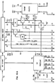
- Fig.1 The environment or general system in which the present invention finds application is shown in Fig.1. It is a dual-bus communication system with a plurality of nodes or stations attached to each of the busses, and with two headend functions at the ends of the two busses. Each of the headend functions may be integrated with a node station as indicated in Fig.1 (e.g. headend HEAD-A with node 1).
- CRMA cyclic-reservation multiple access
- the system comprises an A-bus (11) and a B-bus (13) which serve as transmission medium for the one and the other direction.
- Two headend functions, HEAD-A (15) and HEAD-B (17) are provided.
- a plurality of node stations (19-1 ... 19-N) are attached to both busses.
- Each headend issues fixed-length time slots on its associated bus for use by the nodes.
- the time slots are organized in sequential cycles (of variable length) as indicated in Fig.1. Every cycle is explicitly numbered modulo some maximum number.
- an order pad passing procedure is used (as described in the above-mentioned European patent application).
- Each headend issues, on its associated bus, order pads (and other associated commands) which are transmitted at the leading ends of the time slots, as indicted by darker shaded bars in Fig.1.
- Each order pad is associated with a (future) transmission cycle; any node that wants to transmit data, requests the required number of slots (the "order length") by adding this quantity to a number in the order pad, the "requested length”. It stores the requested number in a Local Reservation Queue, which is shown as box 21 in node N-1,together with the respective cycle number.
- the order pad when arriving at the end of the bus, indicates by the accumulated requested length the total number of slots which are required for that cycle.
- the companion headend which receives the order pad, returns it on its associated bus to the originating headend. There, the accumulated requested length is stored, together with the cycle number, in a Global Reservation Queue, which is shown in HEAD-A as box 23.
- the headend unit issues a cycle start command (also transmitted along the bus in a time slot) containing the respective cycle number, and thereafter releases a number of slots as indicated in its Global Reservation Queue for this cycle.
- a cycle start command also transmitted along the bus in a time slot
- Each station along the bus after recognizing the cycle start command, then uses a number of consecutive free time slots for data transmission which corresponds to the order length number stored in its Local Reservation Queue with that cycle number.
- the headend may issue time slots without a leading cycle start command, as is indicated in Fig.1 by the section "free use" between cycles 5 and 8 (i.e. order pads for cycles 6 and 7 contained no reservations when returning to the headend). During such a period, any station may use any free slot it sees on the bus, without prior reservation.
- Fig.2 there is shown the principle for segmenting data frames prior to transmission so that they can be accomodated in the fixed-length time slots propagating on the bus.
- Each frame (which may be of any length up to a given maximum) and which contains the necessary delimiters SS (start sequence) and ES (end sequence), is simply cut into equal-size segments (payloads) which fit into the fixed-length data segment fields of the time slots.
- a segment header (e.g. a one byte "type" field) is added to each segment payload for identifying the type of segment payload (e.g. FDDI, 802.2, HPPI data, or begin/middle/end/single segment of a frame) and inserted together with the segment payload into a passing free time slot.
- type of segment payload e.g. FDDI, 802.2, HPPI data, or begin/middle/end/single segment of a frame
- each station Due to the cyclic-reservation multiple access (CRMA) technique roughly described above, each station is guaranteed the availability of n consecutive free time slots in a cycle for which it requested n time slots. This is very important because it eliminates the need for extensive protocol information and consecutive numbering of the segment payloads. They arrive at their destination in consecutive time slots (and of course in the same order as they were transmitted).
- CRMA cyclic-reservation multiple access
- each time slot besides a segment payload and associated header (together representing a data channel), also includes a section for commands or signalling information (representing a signalling channel), and of course a slot delimiter.
- a slot is filled up by padding data when the last payload segment does not exactly fit the slot segment size.
- Fig.3 shows the slot format in somewhat more detail. It is assumed here that each slot has a size of p+q bytes (e.g. 58 bytes as an example).
- the actual data segment for the data payload comprises q bytes (e.g. 53 bytes).
- the remaining p bytes (e.g. 5 bytes) are provided for system information.
- One byte represents the slot delimiter, the following bytes are representing an Access Control Field ACF (containing the commands or signalling information, to be explained later in more detail), and the last remaining byte is provided for the segment header (as shown in Fig.2).
- the first field (e.g. two bits) of each ACF contains Slot Control (SC) information. One of these bits may indicate whether the slot is a free-use slot not associated with a specific numbered cycle (cf. Fig.1); the other bit "B/F" indicates whether the slot's data segment is busy (occupied) or free.
- SC Slot Control
- the Global Reservation Queue stored in the headend contains in each entry, as already mentioned above, a cycle number and the associated requested length (i.e. the accumulated number of time slots requested by all the nodes for that cycle).
- the Local Reservation Queue contains in each entry a cycle number and an associated order length, i.e. the number of slots requested by the respective station for the cycle indicated.
- An extra bit in each entry indicates the status of the entry as being pending or confirmed. Initially, the bit is set to zero, indicating pending state.
- the headend station can accept the reservations for a particular cycle by issuing a "Confirm” command with the respective cycle number, or by issuing a "reject” command which cancels all pending reservations of cycles which were not yet confirmed.
- Each node when receiving a confirm command, converts the status of the entry for the respective cycle number to "confirmed" by setting the bit to one. Only then, the reservation is valid. However, each station receiving a reject command cancels all reservations which are still in the "pending" status (these reservations must be repeated later). Details of these procedures are also described in the aforementioned European patent application.
- Priorities are implemented by replicating the reservation queues both at the headends and nodes. Thus, for each priority there is a separate reservation mechanism, and separate Local and Global Reservation Queues are maintained. All the commands are then also associated with one of the priorities. Access commands and cycles with higher priority preempt lower priority access commands and cycles. However, to simplify the description, all steps and procedures are only explained for one priority in the following description.
- each slot issued by the headend is only used once, i.e. it is utilized only during a portion (fraction) of its propagation along the respective bus.
- Node 4 requests 7 slots destined to node 5, and nodes 5, 6, and 7 are requesting 4,7, and 9 slots, all destined to the server-2 (SER-2, i.e. node 8).
- the headend must issue 40 slots which, however, are actually utilized only for a fraction of their existence, as is illustrated in Fig.5 and the following Table II.
- the invention provides a major improvement in this situation.
- CRMA cyclic-reservation multiple access
- slot reuse allows for significant increase in network capacity and reduced access delay under high load without giving up the basic CRMA advantages.
- each node is allowed to reset the "requested length" parameter of the order pad to zero, whenever it is guaranteed that all requested slots (i.e. the segment payloads they contain) will have reached their destination upon arrival at this node.
- the reservation process can restart as if the order pad was issued by a headend, leading to an overall cycle length which is much shorter than in basic CRMA, i.e. the capacity increases and the access delay is reduced.
- node labels which indicate the node positions along the bus must be introduced and some information about the destinations of the requested slots must be included in the order pad command. Furthermore, an indication about the reuse possibility in the data transmission process must be added to the Local Reservation Queues (to be explained later in more detail in connection with Fig .7). The Global Reservation Queue is not changed.
- the order pad command for CRMA with slot reuse contains now three parameters which are processed at the nodes.
- the "Requested Length” (REQ-LEN) parameter is similar to the same parameter in basic CRMA, except that it contains the accumulated number of ordered slots since its last reset to zero.
- the "Requested Maximum” (REQ-MAX) parameter saves the absolute maximum of the Requested Length within that cycle. It is initially set to zero and updated by each node whenever the accumulated Requested Length is larger than the current value of Requested Maximum.
- the "Destination Maximum” (DST-MAX) holds the node label of the most downstream destination of the already requested slots.
- the order pad information is carried in the signalling channel fields of consecutive slots.
- Each ACF field comprises three bytes.
- SC Slot Control
- PRI two bits for the priority.
- the other two bytes of the ACF field contain the parameter(s) of the respective command.
- the three order pad commands (partial commands) have a modified structure to accomodate the additional fields for the Requested Maximum and the Destination Maximum, respectively (besides the fields for command code, cycle priority, cycle number, and Requested Length).
- the slot structure shown in Fig.3 described in the aforementioned European patent application, which provided two bytes for the ACF, that field now has a size of three bytes.
- Fig.6 shows seven different commands; some commands such as RECOVERY or NOOP are not shown here because they are not relevant for the invention. Due to the four-bit command code words, a total of 16 different commands is possible.
- the Local Reservation Queues are also modified and contain, in each entry (and for each priority separately), besides the cycle number, requested length, and a pending/confirmed status indication, also a "reuse flag" (REU-FLG), as is illustrated in Fig.7.
- REU-FLG a "reuse flag"
- the Global Reservation Queue in the headend needs not to be different because the slot reuse mechanism is transparent (not visible) to the headend; it merely takes the Requested Maximum as total (accumulated) requested length instead of the Requested Length per se.
- the Destination Maximum (DST-MAX), which contains the most downstream destination of all upstream requests, is compared with the own node label j. If the Destination Maximum is smaller or equal than the node label j, slot reuse is possible, i.e. all requested slots of the upstream nodes will have reached their destinations upon arrival at this node.
- the node sets in the Local Reservation Queue the "Reuse Flag" REU-FLG(x) for that cycle x (which will cause later, after actual start of the respective cycle, the use of the first data slots after the cycle start command for transmitting the S(j) data units (segment payloads) of that node, and a resetting of all busy/free bits of the remaining slots to "free").
- the 'non-reusing node' sets the Reuse Flag in the Local Reservation Queue to 'false'.
- the Requested Maximum reflects the maximum number of requested slots which ever occurred during the passing of this specific order pad, in order to guarantee that the generated cycle length will be sufficient for all transmissions.
- each slot can be used several times during its passage along its bus.
- the total cycle length, in this example, is reduced by a factor of two because only 20 slots need to be issued by the headend instead of 40 slots.
- Fig.10 is a block diagram of apparatus implementing the control functions for slot reuse in an order pad passing system. This control apparatus is provided in each of the nodes of the dual bus system.
- ACF extraction means 27 In the transmission medium 25, there is provided ACF extraction means 27 and, connected to it, ACF processing means 29 which receives and tests the data contained in the Access Control Field (ACF) of each slot passing on the transmission medium.
- ACF change/insertion means 31 allows to change the information contained in a passing ACF, or to insert new information into specific fields of each passing slot ACF.
- Fig.10 Also shown in Fig.10 are the storage for the Local Reservation Queue 33 (which will not be described in detail) and a queue storage accessing control section 35 connected to it.
- the Local Reservation Queue is connected to other portions of the node (which are not shown here) by lines 37.
- a further section contains the transmit requests of the respective node, in particular the desired number of slots and the respective destination, is shown as block 39. It is connected to the queue storage accessing control 35 by lines 41, and to other portions of the node (not shown here) by lines 43. It provides on output lines 45 the desired number of slots as Order Length ORD-LEN S(j), and on lines 47 the node label of the destination as Order Destination ORD-DST D(j).
- control signal on line 59 causes resetting of the Reuse Flag in the entry of the Local Reservation Queue for the respective cycle number.
- the cycle number is provided on lines 63 to queue storage accessing control section 35.
- the Destination Maximum DST-MAX appearing on lines 55, and the order Destination ORD-DST appearing on lines 47, are compared in comparison means 65. If the (locally requested) ORD-DST is greater then the arriving DST-MAX, then a control signal is activated on the output of comparison means 65 and passed through AND gate 67, control line 69 and OR gate 71 to gating means 73 which passes the ORD-DST from lines 47 to a DST-MAX line 75 for insertion into the respective field of the passing slot ACF. If the arriving DST-MAX value was greater then the local ORD-DST, then the DST-MAX in the passing slot ACF is not changed.
- the Requested Length which is contained in the next arriving slot ACF appears on lines 77 (REQ-LEN (IN)). It is augmented by the Order Length ORD-LEN S(j) (appearing on lines 45) in adding means 79 and the new augmented Requested Length is furnished via lines 81 and OR gates 83 to lines 85 (REQ-LEN (OUT)) for insertion into the respective field of the passing slot ACF.
- control signal on line 61 causes the Reuse Flag (REU-FLG) in the entry of the Local Reservation Queue for the respective cycle to be set.
- the locally desired Order Destination (ORD-DST) D(j) appearing on lines 47 is gated via gating means 73 to DST-MAX output lines 75 for insertion into the DST-MAX field of the passing slot ACF (the existing value in this field is overwritten).
- a control signal is furnished to gating means 73 through OR gate 71 from line 61.
- Order Length ORD-LEN S(j) appearing on lines 45 is gated, by gating means 87, through OR gates 83 to the REQ-LEN (OUT) lines 85 to cause insertion of the locally requested Order Length into the REQ-LEN field of the next slot ACF.
- the existing value is overwritten (it was saved already by a previous node into the field REQ-MAX).
- the Requested Maximum REQ-MAX of the slot ACF of the third arriving slot comprising an order pad command, appearing on lines 89 is compared in comparing means 91 to the requested length REQ-LEN appearing on lines 85 which was inserted into the ACF of the previous slot. If the Requested Length REQ-LNG is greater than the existing REQ-MAX, the latter is overwritten by the former, caused by a control signal on line 93. Otherwise, the REQ-MAX value in the passing slot ACF is not changed.
- a respective signal When a cycle start command is detected in a slot ACF, a respective signal will be activated on line 95. This causes interrogation of the entry for the respective cycle in the Local Reservation Queue, and if the Reuse Flag is set for that cycle, a respective signal is activated on line 97. This causes the setting of a Reuse Latch 99. Its output signal on line 101, the activated, will cause the node to insert its n payload segments for that cycle into the next n passing slots. The control signal on line 101 further causes the setting of the free/busy bit in all passing slots to "free", until the next cycle start control signal appears which will cause resetting of the Reuse Latch 99. Thus, the respective node will release only free slots (except for the first n slots which it uses for itself) within the current cycle for use by the following nodes downstream.
- node control circuitry No further details of the node control circuitry are shown here because they are not relevant for the present invention which is concerned with slot reuse, and because they are described already in the aforementioned European patent application.
- Labels are required in order to decide during the order pad passing process whether requested slots will have reached their destination when they pass at a certain node.
- the headend assigns the labels to the nodes via a "label" command which contains a Node Number (NOD-NUM) parameter.
- NOD-NUM Node Number
- the Node Number is initially set to zero.
- Each active node increments the Node Number by one, uses the result as its label, and passes the command with the incremented parameter to the next node.
- the labels are assigned to the nodes such that they correspond to the position of the active nodes down the bus, i.e. the headend gets label "1" and the last node on the bus gets the highest label number.
- the labels on the A-bus and B-bus are different.
- A-Bus label and B-Bus label are equal to the total number of active nodes plus 1 (if the node labels start with 1). Use of the same labels for both buses is possible, but would require slightly different reservation algorithms for the two buses.
- the assignment of the various types of addresses, e.g. IEEE 802 addresses, to the labels is done via higher layer protocols.
- Fig.10 also shows the means necessary in each node for implementing the node label assignment procedure.
- the respective indicator signal on line 103 is activated.
- the current node number (NOD-NUM) of the received label command appears on lines 105. It should represent the node label of the previous node upstream the transmission medium.
- adding means 107 this node number increased by one unit, and furnished on lines 109 for storing it in the local node label register 51 (thereafter appearing as node label j on its output), and for reinserting the new (increased) node number into the ACF field containing the label command, which further propagates down the transmission medium.
- the label command reaches the end of the respective bus, all nodes will have node labels in ascending order.
Claims (11)
- Ein Verfahren für die Mehrfachzugriffssteuerung in einem Kommunikationssystem mit Knoten, die mit einem Übermittlungsbus verbunden sind, wobei in diesem System Zeitschlitze in numerierten Zyklen freigegeben und ein Reservierungsblock zuvor für jeden numerierten Zyklus übermittelt wird, der eine Anforderungszählung (REQ-LEN) enthält, die von jedem Knoten für die Reservierung von Zeitschlitzen erhöht wird, und wobei das Verfahren die folgenden Schritte zur Reduzierung der Anzahl von Zeitschlitzen umfaßt, die freigegeben werden müssen:- der Transport einer weitesten Zielidentifizierung (DST-MAX) in jedem Reservierungsblock, die von jedem Knoten aktualisiert wird, der Zeitschlitze für die Datenübertragung zu einem ausgewählten Zielknoten reserviert;- die Festlegung von Teilen des Übertragungsbusses auf der Grundlage der weitesten Zielidentifizierung, wobei die Teile jeweils zwischen zwei der Knoten sind, nach denen keine Daten mehr in Zeitschlitzen des entsprechenden Zyklus übermittelt werden müssen;- den erneuten Start der Anforderungszählung für jeden Teil und die Beibehaltung des Maximalwertes der Anforderungszählung von jedem Teil als angefordertes Maximum (REQ-MAX) für den entsprechenden Zyklus;- die Freigabe einer Anzahl von Zeitschlitzen für jeden Zyklus, die dem angeforderten Maximum für diesen Zyklus entsprechen; und- die Wiederverwendung aller Zeitschlitze während jedes Zyklus, die einen Knoten durchlaufen, der zwischen zwei der für diesen Zyklus festgelegten Teile liegt.
- Ein Verfahren nach Anspruch 1, das folgende weitere Schritte umfaßt:- die Zuordnung von Identifizierungsknotenlabels (NOD-LBL) zu allen Knoten in steigender Reihenfolge;- die Bereitstellung eines Feldes mit dem Knotenlabel für das weiteste Ziel (DST-MAX) sowie eines Feldes für ein angefordertes Maximum (REQ-MAX), neben einer Zyklusnummer (CYC-NUM) und eines Feldes für die Anforderungszählung (REQ-LEN) in jedem Reservierungsblock;- in jedem Knoten, der Zeitschlitze für die Datenübermittlungs reservieren will:(a) wenn das Knotenlabel für das weiteste Ziel (DST-MAX) in einem empfangenen Reservierungsblock kleiner oder gleich wie das eigene lokale Knotenlabel ist, erfolgt das Setzen einer lokalen Neustartanzeige (REU-FLG) und der erneute Start der Anforderungszählung (REQ-LEN) im Reservierungsblock;(b) die Aktualisierung der Anforderungszählung (REQ-LEN) in einem empfangenen Reservierungsblock, indem die lokal erforderliche Anzahl von Zeitschlitzen (ORD-LEN) addiert wird, und das Knotenlabel für das weiteste Ziel aktualisiert wird, indem das Knotenlabel für das ausgewählte Ziel (ORD-DST) für die lokalen, zu übermittelnden Daten eingefügt wird, wenn letzteres größer als das im Reservierungsblock empfangene Knotenlabel für das weiteste Ziel ist; und(c) die Übertragung der sich ergebenden Anforderungszählung (REQ-LEN) in das Feld für das angeforderte Maximum (REQ-MAX), wenn der Inhalt des letzteren kleiner als die sich ergebende Anforderungszählung ist.
- Ein Mehrfachzugriffssteuerverfahren für ein Kommunikationssystem mit Knoten, die mit einem Übermittlungsbus und Kopfendemittel zur Erzeugung von Zeitschlitzen und Reservierungsblöcken für numerierte Zyklen verbunden sind; jeder Reservierungsblock umfaßt eine Zyklusnummer (CYC-NUM) und eine Anforderungszählung (REQ-LEN), die jeder Knoten durch eine angeforderte Zeitschlitznummer (ORD-LEN) ändern kann; jeder Knoten verwendet nach dem Start des entsprechenden Betriebszyklus die angeforderte Anzahl freier Zeitschlitze; und jeder Knoten wird von einem Label (NOD-LBL) identifiziert, das seine Lage anzeigt; wobei das Verfahren folgende Schritte umfaßt:
die Bereitstellung von Feldern für ein Knotenlabel für das weiteste Ziel (DST-MAX) und für ein angefordertes Maximum (REQ-MAX) in jedem Reseriverungsblock, wobei der Inhalt der Felder zu Beginn auf Null gesetzt ist;
in jedem Knoten, der Zeitschlitze für die Übertragung lokaler Daten zu einem ausgewählten Ziel anfordern will:(1) der Vergleich des Knotenlabels für das weiteste Ziel (DST-MAX) mit dem eigenen Knotenlabel (NOD-LBL); und entweder(a) wenn das Knotenlabel für das weiteste Ziel gleich wie das eigene Knotenlabel ist, das Identifizieren eines Upstream-Knotens;- das Ersetzen des Knotenlabels für das weiteste Ziel (DST-MAX) durch das Knotenlabel für das ausgewählte Ziel (ORD-DST);- das Ersetzen der aktuellen Anforderungszählung (REQ-LEN) durch die angeforderte Zeitschlitznummer (ORD-LEN);- das Speichern einer lokalen Neustartanzeige (REU-FLG) für den entsprechenden Betriebszyklus im anfordernden Knoten; oder(b) wenn das Knotenlabel für das weiteste Ziel einen Downstream-Knoten identifiziert:- das Ersetzen des Knotenlabels für das weiteste Ziel (DST-MAX) durch das Knotenlabel für das ausgewählte Ziel (ORD-DST),
wenn letzteres größer ist;- das Ändern der aktuellen Anforderungszählung (REQ-LEN) durch die angeforderte Zeitschlitznummer (ORD-LEN); und(2) das Ersetzen des angeforderten Maximums (REQ-MAX) durch die sich ergebende Anforderungszählung (REQ-LEN), wenn letzteres größer ist. - Ein Verfahren nach Anspruch 3, das dadurch gekennzeichnet ist, daß jeder Reservierungsblock zu seinem ursprünglichen Kopfendemittel zurückgesendet wird, und daß der Wert des angeforderten Maximums (REQ-MAX) im zurückgesendeten Reservierungsblock zusammen mit der entsprechenden Betriebszyklusnummer (CYC-NUM) in einem Eintrag einer globalen Reservierungsschlange im Kopfendemittel gespeichert wird.
- Ein Verfahren nach Anspruch 2 oder 3, das dadurch gekennzeichnet ist, daß die lokale Neustartanzeige (REU-FLG) zusammen mit der entsprechenden Zyklusnummer (CYC-NUM) und der Anzahl der angeforderten Zeitschlitze (ORD-LEN) in einem Eintrag einer lokalen Reservierungsschlange in jedem Knoten gespeichert wird.
- Ein Verfahren nach Anspruch 2 oder 3, das in einem System angewendet wird, wo jeder Zeitschlitz eine Belegt/Frei-Anzeige enthält, die auf belegt eingestellt wird, wenn ein Knoten Daten in den Schlitz schreibt, und in dem jeder Betriebszyklus von einem Startbefehl des numerierten Zyklus gestartet wird, wobei das Verfahren dadurch gekennzeichnet ist, daß ein Knoten mit einer lokalen Neustartanzeige (REU-FLG) für jeden beliebigen Zyklus nach der Erfassung des Zyklusstartbefehls für diesen Zyklus die ersten Schlitze nach dem Zyklusstartbefehl zur Übermittlung seiner lokalen Daten verwendet, und dann die Belegt/Frei-Anzeige in allen folgenden Zeitschlitzen auf frei einstellt, bis der nächste Zyklusstartbefehl erfaßt wird.
- Ein Verfahren nach Anspruch 2 oder 3, das in einem System angewendet wird, in dem jeder Reservierungsblock über die Steuerfelder zahlreicher aufeinanderfolgender Zeitschlitze verteilt ist; wobei das Verfahren dadurch gekennzeichnet ist, daß das Feld mit dem Knotenlabel für das weiteste Ziel (DST-MAX) im ersten der Steuerfelder enthalten ist.
- Ein Verfahren nach Anspruch 2 oder 3, das dadurch gekennzeichnet ist, daß für die Zuordnung von Knotenlabels in steigender Reihenfolge zu den Knoten ein Labelbefehl ausgegeben wird, der die anfänglich auf Null gestellte Knotennummer (NOD-NUM) enthält; daß jeder Knoten, der den Labelbefehl empfängt, die Knotennummer (NOD-NUM) um eins erhöht und dann den neuen Wert der Knotennummer als sein eigenes Knotenlabel (NOD-LBL) speichert und den Labelbefehl zum nächsten Knoten übermittelt.
- Eine Vorrichtung für die mehrfache Verwendung von Zeitschlitzen in einem Kommunikationssystem mit einem eindirektionalen Übermittlungsmedium (11; Fig. 1), mehreren daran angeschlossenen Knoten (19-1 ... 19-N) und einem Kopfendemittel (15) zur Erzeugung von Übermittlungszeitschlitzen und Steuerinformationsübermittlung auf dem Übermittlungsmedium; ein Reservierungsblock wird für jeden der zahlreichen numerierten Betriebszyklen übermittelt, der eine Anforderungszählung (REQ-LEN) enthält, die jeder Knoten durch eine angeforderte Zeitschlitznummer (ORD-LEN) ändern kann; jeder Knoten benutzt nach dem Start des entsprechenden Betriebszyklus die angeforderte Anzahl freier Zeitschlitze; und jeder Knoten wird durch ein Label (NOD-LBL) identifiziert, das seine Position anzeigt; wobei die Vorrichtung folgendes umfaßt:
im Kopfendemittel- ein Mittel zur Erzeugung von Reservierungsblöcken (Fig. 6; A, B, C), die neben einer Zyklusnummer (CYC-NUM) und einem Feld für die Anforderungszählung (REQ-LEN) noch Felder mit dem Knotenlabel für das weiteste Ziel (DST-MAX) bzw. mit dem angeforderten Maximum (REQ-MAX) enthalten; und
in jedem Knoten- ein Mittel (51; Fig. 10) zum Speichern eines lokalen Knotenlabels (NOD-LBL);- ein Mittel (39) zum Speichern des Labels (ORD-DST) eines ausgewählten Zielknotens, zu dem die lokalen Daten übermittelt werden;- ein Mittel (57) zum Vergleich des Knotenlabels für das weiteste Ziel in einem empfangenen Reservierungsblock mit dem lokalen Knotenlabel;- Mittel (33, 35, 61) zum Speichern der Zyklusnummer zusammen mit dem Wiederverwendungs-Flag (REU-FLG), wenn das Knotenlabel für das weiteste Ziel kleiner oder gleich wie das lokale Knotenlabel ist, und Mittel (31, 47, 73, 75) zum Einfügen des Knotenlabels für das ausgewählte Ziel in das Feld mit dem Knotenlabel für das weiteste Ziel (DST-MAX) im Reservierungsblock; und- Mittel (31, 95, 97, 99, 101) zur Bereitstellung - nach dem Start eines entsprechenden Betriebszyklus, für den der Knoten ein Wiederverwendungs-Flag reserviert hat, - aller Zeitschlitze des entsprechenden Betriebszyklus, die vom entsprechenden Knoten oder von anderen Knoten in Richtung downstream verwendet werden. - Eine Vorrichtung nach Anspruch 9, die dadurch gekennzeichnet ist, daß jeder Knoten weiterhin folgendes umfaßt:- ein Mittel (91) zum Vergleich des angeforderten Maximums (REQ-MAX) in einem empfangenen Reservierungsblock mit der aktuellen Reservierungszählung (REQ-LEN); und- Mittel (31, 85, 93) zum Ersetzen des angeforderten Maximums durch die aktuelle Anforderungszählung, wenn letztere größer ist.
- Eine Vorrichtung nach Anspruch 9, die dadurch gekennzeichnet ist, daß jeder Knoten weiterhin umfaßt:- ein Mittel (45) zum Speichern einer angeforderten Anzahl von Schlitzen (ORD-LEN);- Mittel (45, 61, 83, 85, 87) zum Ersetzen der aktuellen Anforderungszählung (REQ-LEN) in einem empfangenen Reservierungsblock durch die angeforderte Anzahl von Schlitzen (ORD-LEN), wenn das Knotenlabel für das weiteste Ziel (DST-MAX) kleiner oder gleich wie das lokale Knotenlabel (NOD-LBL) ist, oder zum Addieren der angeforderten Anzahl von Schlitzen zu der aktuellen Anforderungszählung, wenn das Knotenlabel für das weiteste Ziel größer als das lokale Knotenlabel ist.
Priority Applications (4)
| Application Number | Priority Date | Filing Date | Title |
|---|---|---|---|
| EP90810294A EP0451426B1 (de) | 1990-04-11 | 1990-04-11 | Mehrfachzugriffssteuerung für ein Kommunikationssystem mit Reservierungsblockübermittlung |
| DE69013886T DE69013886T2 (de) | 1990-04-11 | 1990-04-11 | Mehrfachzugriffssteuerung für ein Kommunikationssystem mit Reservierungsblockübermittlung. |
| JP3070638A JP2500080B2 (ja) | 1990-04-11 | 1991-03-11 | 通信システムにおける多重アクセス制御方法及び装置 |
| US07/672,216 US5173898A (en) | 1990-04-11 | 1991-03-20 | Multiple-access control for a communication system with order pad passing |
Applications Claiming Priority (1)
| Application Number | Priority Date | Filing Date | Title |
|---|---|---|---|
| EP90810294A EP0451426B1 (de) | 1990-04-11 | 1990-04-11 | Mehrfachzugriffssteuerung für ein Kommunikationssystem mit Reservierungsblockübermittlung |
Publications (2)
| Publication Number | Publication Date |
|---|---|
| EP0451426A1 EP0451426A1 (de) | 1991-10-16 |
| EP0451426B1 true EP0451426B1 (de) | 1994-11-02 |
Family
ID=8205920
Family Applications (1)
| Application Number | Title | Priority Date | Filing Date |
|---|---|---|---|
| EP90810294A Expired - Lifetime EP0451426B1 (de) | 1990-04-11 | 1990-04-11 | Mehrfachzugriffssteuerung für ein Kommunikationssystem mit Reservierungsblockübermittlung |
Country Status (4)
| Country | Link |
|---|---|
| US (1) | US5173898A (de) |
| EP (1) | EP0451426B1 (de) |
| JP (1) | JP2500080B2 (de) |
| DE (1) | DE69013886T2 (de) |
Cited By (8)
| Publication number | Priority date | Publication date | Assignee | Title |
|---|---|---|---|---|
| US5838687A (en) * | 1995-12-28 | 1998-11-17 | Dynarc Ab | Slot reuse method and arrangement |
| US5946315A (en) * | 1995-12-28 | 1999-08-31 | Dynarc Inc. | Method and device for synchronizing dynamic synchronous transfer mode in a ring topology |
| US5960002A (en) * | 1995-12-28 | 1999-09-28 | Dynarc Ab | Defragmentation method and arrangement |
| US5982747A (en) * | 1995-12-28 | 1999-11-09 | Dynarc Inc. | Method for managing failures on dynamic synchronous transfer mode dual ring topologies |
| US5982780A (en) * | 1995-12-28 | 1999-11-09 | Dynarc Ab | Resource management scheme and arrangement |
| US6108338A (en) * | 1995-12-28 | 2000-08-22 | Dynarc Inc. | Method and device for dynamic synchronous transfer mode in a dual ring topology |
| WO2002043321A2 (en) * | 2000-11-21 | 2002-05-30 | Lockheed Martin Company | Method of bus arbitration in a multi-master system |
| USRE41247E1 (en) | 1997-04-01 | 2010-04-20 | Lockheed Martin Corporation | Optical transport system |
Families Citing this family (14)
| Publication number | Priority date | Publication date | Assignee | Title |
|---|---|---|---|---|
| US5361262A (en) * | 1993-04-16 | 1994-11-01 | Bell Communications Research, Inc. | Estimated-queue, expanded-bus communication network |
| US5555244A (en) * | 1994-05-19 | 1996-09-10 | Integrated Network Corporation | Scalable multimedia network |
| US5613073A (en) * | 1994-07-25 | 1997-03-18 | International Business Machines Corporation | Apparatus and method for a buffer reservation system |
| JP3595836B2 (ja) * | 1995-05-12 | 2004-12-02 | 株式会社 東芝 | 通信システム |
| US5790806A (en) * | 1996-04-03 | 1998-08-04 | Scientific-Atlanta, Inc. | Cable data network architecture |
| SE508889C2 (sv) * | 1996-03-25 | 1998-11-16 | Net Insight Ab | Metod och anordning för dataöverföring med parallella bitströmmar |
| SE506548C2 (sv) * | 1996-03-25 | 1998-01-12 | Net Insight Ab | Metod och anordning för dynamisk signalering i ett tidsmultiplexat system |
| US6839322B1 (en) * | 2000-02-09 | 2005-01-04 | Nortel Networks Limited | Method and system for optical routing of variable-length packet data |
| US6891855B2 (en) * | 2000-07-27 | 2005-05-10 | Corrigent Systems, Ltd. | Dynamic packet fragmentation |
| US6985510B2 (en) * | 2000-12-22 | 2006-01-10 | Qualcomm, Incorporated | Method and system for data and voice transmission over shared and dedicated channels |
| US6876669B2 (en) * | 2001-01-08 | 2005-04-05 | Corrigent Systems Ltd. | Packet fragmentation with nested interruptions |
| US8072999B1 (en) * | 2007-05-08 | 2011-12-06 | Motion Engineering Inc. | Method and system for removing and returning nodes in a synchronous network |
| US8135893B2 (en) | 2008-09-12 | 2012-03-13 | Honeywell International, Inc. | System, apparatus and method for granting access to a shared communications bus |
| US10230665B2 (en) * | 2013-12-20 | 2019-03-12 | Intel Corporation | Hierarchical/lossless packet preemption to reduce latency jitter in flow-controlled packet-based networks |
Family Cites Families (9)
| Publication number | Priority date | Publication date | Assignee | Title |
|---|---|---|---|---|
| US4387458A (en) * | 1981-05-28 | 1983-06-07 | Bell Telephone Laboratories, Incorporated | High capacity secure address loop network |
| US4460994A (en) * | 1981-10-05 | 1984-07-17 | At&T Bell Laboratories | Loop communication system |
| US4528663A (en) * | 1983-12-09 | 1985-07-09 | Zenith Electronics Corporation | Peak load access in a two-way CATV contention system |
| US4663748A (en) * | 1984-04-12 | 1987-05-05 | Unisearch Limited | Local area network |
| DE3424866C2 (de) * | 1984-07-06 | 1986-04-30 | Messerschmitt-Bölkow-Blohm GmbH, 8012 Ottobrunn | Verfahren und Anordnung zur Übertragung von Daten, insbesondere in einem Flugzeug |
| DE3586796T2 (de) * | 1984-12-03 | 1993-05-13 | Univ Western Australia | Protokoll fuer warteschlange. |
| EP0212031B1 (de) * | 1985-08-13 | 1990-11-07 | International Business Machines Corporation | Mechanismus zur dynamischen Zuordnung von Bandbreite zwischen Durchschaltkanälen und Paketbitstrom in einem Nachrichtennetz |
| DE68920028T2 (de) * | 1989-04-21 | 1995-07-06 | Ibm | Verfahren und Vorrichtung zum Vielfachzugriff mit zyklischer Reservierung in einem Kommunikationssystem. |
| US5003531A (en) * | 1989-08-11 | 1991-03-26 | Infotron Systems Corporation | Survivable network using reverse protection ring |
-
1990
- 1990-04-11 DE DE69013886T patent/DE69013886T2/de not_active Expired - Fee Related
- 1990-04-11 EP EP90810294A patent/EP0451426B1/de not_active Expired - Lifetime
-
1991
- 1991-03-11 JP JP3070638A patent/JP2500080B2/ja not_active Expired - Lifetime
- 1991-03-20 US US07/672,216 patent/US5173898A/en not_active Expired - Lifetime
Cited By (10)
| Publication number | Priority date | Publication date | Assignee | Title |
|---|---|---|---|---|
| US5838687A (en) * | 1995-12-28 | 1998-11-17 | Dynarc Ab | Slot reuse method and arrangement |
| US5946315A (en) * | 1995-12-28 | 1999-08-31 | Dynarc Inc. | Method and device for synchronizing dynamic synchronous transfer mode in a ring topology |
| US5960002A (en) * | 1995-12-28 | 1999-09-28 | Dynarc Ab | Defragmentation method and arrangement |
| US5982747A (en) * | 1995-12-28 | 1999-11-09 | Dynarc Inc. | Method for managing failures on dynamic synchronous transfer mode dual ring topologies |
| US5982780A (en) * | 1995-12-28 | 1999-11-09 | Dynarc Ab | Resource management scheme and arrangement |
| US6108338A (en) * | 1995-12-28 | 2000-08-22 | Dynarc Inc. | Method and device for dynamic synchronous transfer mode in a dual ring topology |
| USRE41247E1 (en) | 1997-04-01 | 2010-04-20 | Lockheed Martin Corporation | Optical transport system |
| US6320863B1 (en) | 1998-04-17 | 2001-11-20 | Dynarc Inc. Dba Dynamic Network Architecture Inc. | Backplane architecture for dynamic synchronous transfer mode |
| WO2002043321A2 (en) * | 2000-11-21 | 2002-05-30 | Lockheed Martin Company | Method of bus arbitration in a multi-master system |
| WO2002043321A3 (en) * | 2000-11-21 | 2003-03-13 | Lockheed Martin Company | Method of bus arbitration in a multi-master system |
Also Published As
| Publication number | Publication date |
|---|---|
| DE69013886D1 (de) | 1994-12-08 |
| DE69013886T2 (de) | 1995-05-18 |
| US5173898A (en) | 1992-12-22 |
| JPH04250737A (ja) | 1992-09-07 |
| JP2500080B2 (ja) | 1996-05-29 |
| EP0451426A1 (de) | 1991-10-16 |
Similar Documents
| Publication | Publication Date | Title |
|---|---|---|
| EP0451426B1 (de) | Mehrfachzugriffssteuerung für ein Kommunikationssystem mit Reservierungsblockübermittlung | |
| EP0462349B1 (de) | Breitbandringkommunikationssystem und Zugriffssteuerungsverfahren | |
| US5081622A (en) | Method and apparatus for distributed queue multiple access in a communication system | |
| US5136582A (en) | Memory management system and method for network controller | |
| US3988545A (en) | Method of transmitting information and multiplexing device for executing the method | |
| US5210750A (en) | Method and apparatus for distributed queue multiple access in a communication system | |
| US7085847B2 (en) | Method and system for scheduling network communication | |
| EP0459757B1 (de) | Netzwerkanpassungseinrichtung | |
| EP0042447A1 (de) | Durchflusskontrollvorrichtung für Knotenstellen zum Schalten von Blöcken | |
| EP0276349A1 (de) | Vorrichtung zur Vermittlung zwischen Kanälen für synchronen Nachrichtenverkehr und zur Vermittlung von asynchronen Datenpaketen | |
| WO2000019650A1 (en) | Method and system for communication with a network | |
| WO2000019672A1 (en) | Method and system for communicating information in a network | |
| US6973096B2 (en) | System and method for processing bandwidth allocation messages | |
| EP0505658B1 (de) | Verfahren zum Zugriff auf den Übertragungsweg lokaler Netze | |
| US6374314B1 (en) | Method for managing storage of data by storing buffer pointers of data comprising a sequence of frames in a memory location different from a memory location for pointers of data not comprising a sequence of frames | |
| US5337312A (en) | Communications network and method of regulating access to the busses in said network | |
| JPH0716200B2 (ja) | 通信ネツトワークアクセス方法及び装置 | |
| US5214649A (en) | Insert/remove signalling in lan systems | |
| JPH05136797A (ja) | 多重リングlan及び多重リングlanのデータ伝送方法 |
Legal Events
| Date | Code | Title | Description |
|---|---|---|---|
| PUAI | Public reference made under article 153(3) epc to a published international application that has entered the european phase |
Free format text: ORIGINAL CODE: 0009012 |
|
| AK | Designated contracting states |
Kind code of ref document: A1 Designated state(s): DE FR GB |
|
| 17P | Request for examination filed |
Effective date: 19911219 |
|
| K1C3 | Correction of patent application (complete document) published |
Effective date: 19911016 |
|
| 17Q | First examination report despatched |
Effective date: 19931216 |
|
| GRAA | (expected) grant |
Free format text: ORIGINAL CODE: 0009210 |
|
| AK | Designated contracting states |
Kind code of ref document: B1 Designated state(s): DE FR GB |
|
| REF | Corresponds to: |
Ref document number: 69013886 Country of ref document: DE Date of ref document: 19941208 |
|
| ET | Fr: translation filed | ||
| PGFP | Annual fee paid to national office [announced via postgrant information from national office to epo] |
Ref country code: FR Payment date: 19950328 Year of fee payment: 6 |
|
| PGFP | Annual fee paid to national office [announced via postgrant information from national office to epo] |
Ref country code: DE Payment date: 19950428 Year of fee payment: 6 |
|
| PLBE | No opposition filed within time limit |
Free format text: ORIGINAL CODE: 0009261 |
|
| STAA | Information on the status of an ep patent application or granted ep patent |
Free format text: STATUS: NO OPPOSITION FILED WITHIN TIME LIMIT |
|
| 26N | No opposition filed | ||
| PG25 | Lapsed in a contracting state [announced via postgrant information from national office to epo] |
Ref country code: FR Effective date: 19961227 |
|
| PG25 | Lapsed in a contracting state [announced via postgrant information from national office to epo] |
Ref country code: DE Effective date: 19970101 |
|
| REG | Reference to a national code |
Ref country code: FR Ref legal event code: ST |
|
| PGFP | Annual fee paid to national office [announced via postgrant information from national office to epo] |
Ref country code: GB Payment date: 19980319 Year of fee payment: 9 |
|
| PG25 | Lapsed in a contracting state [announced via postgrant information from national office to epo] |
Ref country code: GB Free format text: LAPSE BECAUSE OF NON-PAYMENT OF DUE FEES Effective date: 19990411 |
|
| GBPC | Gb: european patent ceased through non-payment of renewal fee |
Effective date: 19990411 |