EP0451376B1 - Centrifugal blood pump and motor drive - Google Patents
Centrifugal blood pump and motor drive Download PDFInfo
- Publication number
- EP0451376B1 EP0451376B1 EP90303809A EP90303809A EP0451376B1 EP 0451376 B1 EP0451376 B1 EP 0451376B1 EP 90303809 A EP90303809 A EP 90303809A EP 90303809 A EP90303809 A EP 90303809A EP 0451376 B1 EP0451376 B1 EP 0451376B1
- Authority
- EP
- European Patent Office
- Prior art keywords
- shaft
- pump
- impeller
- vane
- axis
- Prior art date
- Legal status (The legal status is an assumption and is not a legal conclusion. Google has not performed a legal analysis and makes no representation as to the accuracy of the status listed.)
- Expired - Lifetime
Links
Images

Classifications
-
- F—MECHANICAL ENGINEERING; LIGHTING; HEATING; WEAPONS; BLASTING
- F04—POSITIVE - DISPLACEMENT MACHINES FOR LIQUIDS; PUMPS FOR LIQUIDS OR ELASTIC FLUIDS
- F04D—NON-POSITIVE-DISPLACEMENT PUMPS
- F04D29/00—Details, component parts, or accessories
- F04D29/04—Shafts or bearings, or assemblies thereof
- F04D29/046—Bearings
- F04D29/047—Bearings hydrostatic; hydrodynamic
-
- A—HUMAN NECESSITIES
- A61—MEDICAL OR VETERINARY SCIENCE; HYGIENE
- A61M—DEVICES FOR INTRODUCING MEDIA INTO, OR ONTO, THE BODY; DEVICES FOR TRANSDUCING BODY MEDIA OR FOR TAKING MEDIA FROM THE BODY; DEVICES FOR PRODUCING OR ENDING SLEEP OR STUPOR
- A61M60/00—Blood pumps; Devices for mechanical circulatory actuation; Balloon pumps for circulatory assistance
- A61M60/10—Location thereof with respect to the patient's body
- A61M60/104—Extracorporeal pumps, i.e. the blood being pumped outside the patient's body
-
- A—HUMAN NECESSITIES
- A61—MEDICAL OR VETERINARY SCIENCE; HYGIENE
- A61M—DEVICES FOR INTRODUCING MEDIA INTO, OR ONTO, THE BODY; DEVICES FOR TRANSDUCING BODY MEDIA OR FOR TAKING MEDIA FROM THE BODY; DEVICES FOR PRODUCING OR ENDING SLEEP OR STUPOR
- A61M60/00—Blood pumps; Devices for mechanical circulatory actuation; Balloon pumps for circulatory assistance
- A61M60/20—Type thereof
- A61M60/205—Non-positive displacement blood pumps
- A61M60/216—Non-positive displacement blood pumps including a rotating member acting on the blood, e.g. impeller
- A61M60/226—Non-positive displacement blood pumps including a rotating member acting on the blood, e.g. impeller the blood flow through the rotating member having mainly radial components
- A61M60/232—Centrifugal pumps
-
- A—HUMAN NECESSITIES
- A61—MEDICAL OR VETERINARY SCIENCE; HYGIENE
- A61M—DEVICES FOR INTRODUCING MEDIA INTO, OR ONTO, THE BODY; DEVICES FOR TRANSDUCING BODY MEDIA OR FOR TAKING MEDIA FROM THE BODY; DEVICES FOR PRODUCING OR ENDING SLEEP OR STUPOR
- A61M60/00—Blood pumps; Devices for mechanical circulatory actuation; Balloon pumps for circulatory assistance
- A61M60/40—Details relating to driving
- A61M60/403—Details relating to driving for non-positive displacement blood pumps
- A61M60/419—Details relating to driving for non-positive displacement blood pumps the force acting on the blood contacting member being permanent magnetic, e.g. from a rotating magnetic coupling between driving and driven magnets
-
- A—HUMAN NECESSITIES
- A61—MEDICAL OR VETERINARY SCIENCE; HYGIENE
- A61M—DEVICES FOR INTRODUCING MEDIA INTO, OR ONTO, THE BODY; DEVICES FOR TRANSDUCING BODY MEDIA OR FOR TAKING MEDIA FROM THE BODY; DEVICES FOR PRODUCING OR ENDING SLEEP OR STUPOR
- A61M60/00—Blood pumps; Devices for mechanical circulatory actuation; Balloon pumps for circulatory assistance
- A61M60/80—Constructional details other than related to driving
- A61M60/802—Constructional details other than related to driving of non-positive displacement blood pumps
- A61M60/804—Impellers
- A61M60/806—Vanes or blades
-
- A—HUMAN NECESSITIES
- A61—MEDICAL OR VETERINARY SCIENCE; HYGIENE
- A61M—DEVICES FOR INTRODUCING MEDIA INTO, OR ONTO, THE BODY; DEVICES FOR TRANSDUCING BODY MEDIA OR FOR TAKING MEDIA FROM THE BODY; DEVICES FOR PRODUCING OR ENDING SLEEP OR STUPOR
- A61M60/00—Blood pumps; Devices for mechanical circulatory actuation; Balloon pumps for circulatory assistance
- A61M60/80—Constructional details other than related to driving
- A61M60/802—Constructional details other than related to driving of non-positive displacement blood pumps
- A61M60/818—Bearings
- A61M60/824—Hydrodynamic or fluid film bearings
-
- A—HUMAN NECESSITIES
- A61—MEDICAL OR VETERINARY SCIENCE; HYGIENE
- A61M—DEVICES FOR INTRODUCING MEDIA INTO, OR ONTO, THE BODY; DEVICES FOR TRANSDUCING BODY MEDIA OR FOR TAKING MEDIA FROM THE BODY; DEVICES FOR PRODUCING OR ENDING SLEEP OR STUPOR
- A61M60/00—Blood pumps; Devices for mechanical circulatory actuation; Balloon pumps for circulatory assistance
- A61M60/80—Constructional details other than related to driving
- A61M60/802—Constructional details other than related to driving of non-positive displacement blood pumps
- A61M60/818—Bearings
- A61M60/825—Contact bearings, e.g. ball-and-cup or pivot bearings
-
- A—HUMAN NECESSITIES
- A61—MEDICAL OR VETERINARY SCIENCE; HYGIENE
- A61M—DEVICES FOR INTRODUCING MEDIA INTO, OR ONTO, THE BODY; DEVICES FOR TRANSDUCING BODY MEDIA OR FOR TAKING MEDIA FROM THE BODY; DEVICES FOR PRODUCING OR ENDING SLEEP OR STUPOR
- A61M60/00—Blood pumps; Devices for mechanical circulatory actuation; Balloon pumps for circulatory assistance
- A61M60/80—Constructional details other than related to driving
- A61M60/802—Constructional details other than related to driving of non-positive displacement blood pumps
- A61M60/827—Sealings between moving parts
-
- F—MECHANICAL ENGINEERING; LIGHTING; HEATING; WEAPONS; BLASTING
- F04—POSITIVE - DISPLACEMENT MACHINES FOR LIQUIDS; PUMPS FOR LIQUIDS OR ELASTIC FLUIDS
- F04D—NON-POSITIVE-DISPLACEMENT PUMPS
- F04D13/00—Pumping installations or systems
- F04D13/02—Units comprising pumps and their driving means
- F04D13/021—Units comprising pumps and their driving means containing a coupling
- F04D13/024—Units comprising pumps and their driving means containing a coupling a magnetic coupling
- F04D13/027—Details of the magnetic circuit
-
- F—MECHANICAL ENGINEERING; LIGHTING; HEATING; WEAPONS; BLASTING
- F04—POSITIVE - DISPLACEMENT MACHINES FOR LIQUIDS; PUMPS FOR LIQUIDS OR ELASTIC FLUIDS
- F04D—NON-POSITIVE-DISPLACEMENT PUMPS
- F04D29/00—Details, component parts, or accessories
- F04D29/08—Sealings
- F04D29/10—Shaft sealings
- F04D29/106—Shaft sealings especially adapted for liquid pumps
-
- F—MECHANICAL ENGINEERING; LIGHTING; HEATING; WEAPONS; BLASTING
- F04—POSITIVE - DISPLACEMENT MACHINES FOR LIQUIDS; PUMPS FOR LIQUIDS OR ELASTIC FLUIDS
- F04D—NON-POSITIVE-DISPLACEMENT PUMPS
- F04D29/00—Details, component parts, or accessories
- F04D29/18—Rotors
- F04D29/22—Rotors specially for centrifugal pumps
- F04D29/24—Vanes
- F04D29/242—Geometry, shape
- F04D29/245—Geometry, shape for special effects
-
- F—MECHANICAL ENGINEERING; LIGHTING; HEATING; WEAPONS; BLASTING
- F16—ENGINEERING ELEMENTS AND UNITS; GENERAL MEASURES FOR PRODUCING AND MAINTAINING EFFECTIVE FUNCTIONING OF MACHINES OR INSTALLATIONS; THERMAL INSULATION IN GENERAL
- F16J—PISTONS; CYLINDERS; SEALINGS
- F16J15/00—Sealings
- F16J15/16—Sealings between relatively-moving surfaces
- F16J15/32—Sealings between relatively-moving surfaces with elastic sealings, e.g. O-rings
- F16J15/3204—Sealings between relatively-moving surfaces with elastic sealings, e.g. O-rings with at least one lip
- F16J15/3232—Sealings between relatively-moving surfaces with elastic sealings, e.g. O-rings with at least one lip having two or more lips
- F16J15/3236—Sealings between relatively-moving surfaces with elastic sealings, e.g. O-rings with at least one lip having two or more lips with at least one lip for each surface, e.g. U-cup packings
-
- F—MECHANICAL ENGINEERING; LIGHTING; HEATING; WEAPONS; BLASTING
- F16—ENGINEERING ELEMENTS AND UNITS; GENERAL MEASURES FOR PRODUCING AND MAINTAINING EFFECTIVE FUNCTIONING OF MACHINES OR INSTALLATIONS; THERMAL INSULATION IN GENERAL
- F16J—PISTONS; CYLINDERS; SEALINGS
- F16J15/00—Sealings
- F16J15/50—Sealings between relatively-movable members, by means of a sealing without relatively-moving surfaces, e.g. fluid-tight sealings for transmitting motion through a wall
-
- H—ELECTRICITY
- H02—GENERATION; CONVERSION OR DISTRIBUTION OF ELECTRIC POWER
- H02K—DYNAMO-ELECTRIC MACHINES
- H02K49/00—Dynamo-electric clutches; Dynamo-electric brakes
- H02K49/10—Dynamo-electric clutches; Dynamo-electric brakes of the permanent-magnet type
- H02K49/104—Magnetic couplings consisting of only two coaxial rotary elements, i.e. the driving element and the driven element
- H02K49/108—Magnetic couplings consisting of only two coaxial rotary elements, i.e. the driving element and the driven element with an axial air gap
-
- H—ELECTRICITY
- H02—GENERATION; CONVERSION OR DISTRIBUTION OF ELECTRIC POWER
- H02K—DYNAMO-ELECTRIC MACHINES
- H02K5/00—Casings; Enclosures; Supports
- H02K5/04—Casings or enclosures characterised by the shape, form or construction thereof
- H02K5/12—Casings or enclosures characterised by the shape, form or construction thereof specially adapted for operating in liquid or gas
- H02K5/128—Casings or enclosures characterised by the shape, form or construction thereof specially adapted for operating in liquid or gas using air-gap sleeves or air-gap discs
Definitions
- the present invention relates to centrifugal blood pumps intended for extracorporeal pumping of blood.
- US Reissue patent 28,742 discloses a pump structure capable of being used as a heart pump.
- the structure utilizes a vortex pump and two impeller surfaces and is the conventional shape for vortex pumps which operate on the principle that a rotating chamber causes rotation of its contents.
- the impeller surfaces are parallel, but separated by supports such that a volume of space is created between the impellers.
- the blood is passed through the volume of space between the impellers and rotates by virtue of the rotation of the impellers.
- ASAIO Transactions 35 (1989) p. 46-53 describes a blood impeller pump having outwardly directed vanes having logarithmic spiral angles that are used in the development of hemolysis data to predict the impeller's optimal shape.
- Another object of the invention is to provide a novel centrifugal blood pump which is structurally simpler than existing pumps of this type, and hence operates more reliably.
- impellers according to the present invention are constructed to subject blood as it enters and flows through the pump to smooth velocity transitions and to reduce cavitation in the pump, particularly at the inlet.
- ⁇ is the angle, at a point along a vane, between a line tangent to the blade surface and a line tangent to a circle passing through that point and centered on the axis of rotation of the shaft, ⁇ 1 is the blade angle in radians, of each vane at its first end;
- Figure 1 is a cross-sectional, elevational view of a preferred embodiment of a centrifugal blood pump according to the present invention.
- Figure 2 is a cross-sectional, elevational view of one element provided in the pump of Figure 1.
- Figure 3 is a top plan view of one impeller component of the pump of Figure 1.
- Figure 4 is a bottom plan view of the second impeller element of the pump shown in Figure 1.
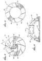
- Figure 5 is a cutaway perspective view of a portion of the magnetic drive system for the pump of Figure 1.
- FIG. 1 is a cross-sectional view taken along a plane passing through the axis of rotation of the pump impeller.
- the illustrated pump includes a housing composed of a forward housing part 2 and a rear housing part 4, parts 2 and 4 together enclosing a pump chamber 6.
- the pump housing further includes a bearing housing 8 and a bearing cap 10, with the rear end of housing 8 being closed by cap 10 and the forward end of housing 8 being closed by rear housing part 4.
- Forward housing part 2 is formed to have an inlet passage 12 which extends along the pump axis and an outlet passage 14 which extends in a generally tangential direction at the periphery of chamber 6.
- Impeller 16 is mounted within chamber 6 within chamber 6 there is mounted an impeller which, according to the present invention, is formed of a forward impeller part 16 and a rear impeller part 18, parts 16 and 18 being joined and bonded together along a plane perpendicular to the pump axis.
- Impeller 16, 18 is mounted on an impeller shaft 20 which is rotatably supported by a pair of journal bearings 22 secured in bearing housing 8.
- the region within housing 8 between bearings 22 is preferably filled with a mass 24 of a suitable grease.
- cap 10 The interior surface of cap 10 is provided with a cylindrical blind bore containing a steel ball 26 which constitutes a thrust bearing providing axial support for shaft 20 and impeller 16, 18.
- Impeller parts 16 and 18 are formed to delimit a plurality of circumferentially spaced, arcuate chambers, six such chambers being provided in one practical embodiment of the invention.
- Each chamber holds an arcuate drive plate 28 made of a magnetically permeable, but unmagnetized, material. Plates 28 can be made relatively thin, a thickness of the order of 0.1 cm (.040") having been found to be suitable.
- Forward impeller part 16 carries a plurality of circumferentially spaced long vanes 30 and a plurality of circumferentially spaced short vanes 32 interposed circumferentially between successive long vanes 30. All vanes 30 and 32 project axially toward inlet passage 12 and the edges of vanes 30 and 32 which face toward inlet passage 12 conform generally to the outline of forward housing part 2.
- Rear impeller part 18 carries a plurality of short vanes 34 each of which is aligned with and corresponds in configuration to a respective one of short vanes 32 and the outer portions of long vanes 30.
- the portion of each long vane 30 which is radially enclosed by a respective vane 34 extends axially toward rear housing part 4 to the same level as the associated vane 34 so that, at the side facing rear housing part 4, the respective vane 34 forms a radial continuation of the associated vane 30.
- Impeller shaft 20 enters chamber 6 via a passage provided in rear housing part 4, which passage is dimensioned to provide the minimum permissible clearance for shaft 20.
- a radial clearance of no more than 0.0025 to 0.005 cm (0.001 to 0.002”) is provided.
- the edge of the shaft passage which borders chamber 6 is formed to be sharp so as to constitute a shear edge.
- the passage for shaft 20 is isolated from the interior of bearing chamber 8 by shaft seal 36.
- shaft seal 36 is composed of an annular flange portion 38 which will bear against the journal bearing 22 which is adjacent rear housing part 4.
- Shaft seal 36 further includes two concentric, radially spaced cylindrical portions 40, the outer one of which bears against the surface of a cylindrical relief opening provided in rear housing part 4.
- Inner cylindrical portion 40 is dimensioned to establish a close fit with shaft 20.
- a pressure member 42 composed of a spiral spring bent into a toroidal form and made of a suitable material, such as stainless spring steel.
- Member 42 is configured to apply a radial pressure to cylindrical portions 40, thereby pressing those portions against shaft 20 and the inner surface of the cylindrical relief opening provided in rear housing part 4, respectively.
- an effective seal is provided between chamber 6 and the interior of bearing housing 8.
- shaft seal 36 is, in effect, "hidden” from chamber 6. This helps to prevent thrombus formation on seal 36.
- seal 36 is not required to effect a perfect sealing action but need only prevent gross migration of blood and grease.
- Figure 3 is a plan view, looking in the direction of fluid flow into the pump, of forward impeller part 16, which is basically composed of an inner hub portion 44 and an outer annular portion 46, the two portions being secured together by means of long vanes 30.
- Short vanes 32 are interposed between long vanes 30 so that vanes 30 and 32 are equispaced about the circumference of upper impeller part 16.
- FIG 4 is a plan view of rear impeller part 18, looking opposite to the direction of fluid flow into the pump, i.e., opposite to the direction of the view of Figure 3.
- Rear impeller part 18 is composed essentially of an annular ring 48 carrying short vanes 34, each of which is aligned with an associated portion of a respective one of vanes 30 or 32.
- each vane 30, 32, 34 is given a curvature such that the variation of the tangent of the blade angle as a function of impeller radius has a positive value along the length of each blade.
- FIGs 3 and 4 additionally illustrate one of the drive plates 28 which is installed between impeller parts 16 and 18 and which are spaced apart around the circumference of the impeller.
- the axial spacing between vanes 30, 32, 34 and housing parts 2 and 4 are of the order of 0.3 cm (0.12 inch) at the outer diameter of the impeller.
- the surface of rear housing part 4 which delimits chamber 6 has a slight upward slope toward shaft 20 so that the axial spacing between the vanes and that surface of lower housing part 4 exhibits a slight progressive decrease in the direction toward shaft 20.
- Vanes 34 and the portions of vanes 30 which project toward rear housing part 4 act to subject blood which is present between the impeller and rear housing part 4 to a radial outward force, and thereby prevent blood from recirculating around the outer edge of the impeller.
- the action of these vane portions together with the sharp shear edge provided by rear housing part 4 around shaft 20 at the side bordering chamber 6 serve to sweep blood away from the region where shaft 20 passes through rear housing part 4, which is a potential area of stasis, and thus prevent thrombus formation at that location.
- vanes 30, 32, 34 are configured with the goal of minimizing the acceleration and shock experienced by blood within the pump.
- the inlet blade angle of each vane is selected so that, for a selected impeller speed, the velocity produced by each vane closely corresponds to the inlet flow velocity of the blood.
- Blade angle, ⁇ is the angle, at a point along a vane, between a line tangent to the blade surface and a line tangent to a circle passing through that point and centered on the axis of rotation of shaft 20.
- FIG. 5 illustrates the basic components of a magnetic drive according to the present invention.
- This drive is composed of a plurality of permanent magnet units 50 mounted on a plate 52 having a central opening 53 for connection to the shaft of a drive motor.
- One-half of the drive is shown in Figure 5.
- Each magnet unit 50 is composed of two bar magnets 54 each having its magnetic axis oriented parallel to the axis of rotation of plate 52, with the magnets 54 of each unit 50 being oriented in polarity opposition to one another, as shown.
- the magnetic poles of each unit 50 are oriented opposite to those of each adjacent unit 50.
- Each unit 50 is further composed of an arcuate plate 56 of ferromagnetic material completing the magnetic circuit at one end of the associated unit 50.
- the magnetic drive is disposed directly beneath rear housing part 4 so that magnet units 50 surround housing 8 and plate 52 is behind cap 10.
- the end of each magnet unit 50 which is remote from plate 52 faces a respective one of plates 28.
- the spacing between plates 28 and units 50 is made as small as possible in order to minimize the air gap between each plate 28 and its associated unit 50, and thus maximize the magnetic attraction exerted on each plate 28.
- the arrangement of magnetic units 50 is such that the magnetic flux path of each unit is completed through a respective one of plates 28 and the magnetic paths associated with adjacent ones of plates 28 are maintained isolated from each other by the orientations of the magnets associated with adjacent units 50.
- the magnetic attraction forces exerted on plates 28 cause impeller 16, 18 to rotate in unison therewith.
- the drive arrangement shown in Figure 5 produces particularly strong magnetic forces, making possible the use of thin, unmagnetized plates 28 and permitting a sufficient drive force to be imparted to impeller 16, 18 even with a comparatively large air gap between units 50 and plates 28.
Description
- The present invention relates to centrifugal blood pumps intended for extracorporeal pumping of blood.
- Known blood pumps of this type have been found to be less than totally reliable, due at least in part to their mechanical complexity and to the use of configurations which permit blood thrombus formation.
- US Reissue patent 28,742 discloses a pump structure capable of being used as a heart pump. The structure utilizes a vortex pump and two impeller surfaces and is the conventional shape for vortex pumps which operate on the principle that a rotating chamber causes rotation of its contents. The impeller surfaces are parallel, but separated by supports such that a volume of space is created between the impellers. The blood is passed through the volume of space between the impellers and rotates by virtue of the rotation of the impellers.
- ASAIO Transactions 35 (1989) p. 46-53 describes a blood impeller pump having outwardly directed vanes having logarithmic spiral angles that are used in the development of hemolysis data to predict the impeller's optimal shape.
- Both of these prior pumps, however, fail to significantly reduce the danger of blood hemolysis and thrombus formation due to the shock experienced by the blood if accelerated.
- It is a primary object of the present invention to provide a novel centrifugal blood pump which reduces the danger of blood hemolysis and thrombus formation.
- Another object of the invention is to provide a novel centrifugal blood pump which is structurally simpler than existing pumps of this type, and hence operates more reliably.
- With regard to this primary aspect of the invention, the applicants have concluded that, in pumps of the type under consideration, blood hemolysis is caused by mechanical stresses imposed on the blood by the pumping process and have conceived and developed a novel impeller configuration which acts on the blood in such a manner as to significantly reduce the occurrence of hemolysis. Basically, impellers according to the present invention are constructed to subject blood as it enters and flows through the pump to smooth velocity transitions and to reduce cavitation in the pump, particularly at the inlet.
- Applicants have determined that this objective can be achieved by giving the impeller vanes a blade angle which varies from the end associated with the pump inlet and to the end associated with the pump outlet such that the tangent of the blade angle increases, as a function of radial distance from the impeller axis. It is presently believed that an optimum result will be achieved if the tangent increases linearly, or at least approximately linearly, from the inlet to the outlet.
- According to the present invention there is therefore provided a centrifugal blood pump comprising an impeller housing having a generally circular cross section and a longitudinal axis and delimiting a blood pumping chamber having a blood inlet port extending along the longitudinal axis and a blood outlet port located at the periphery of the chamber, an impeller provided with a plurality of radially extending curved vanes disposed in the chamber, each vane having a first end adjacent the blood inlet port and a second end extending toward the periphery of the chamber an axial shaft supporting the impeller for rotation about the longitudinal axis of the blood pumping chamber, and drive means for rotating the impeller in a sense to cause the vanes to propel blood radially from the inlet port to the outlet port, characterised in that the vanes include long vanes and each vane is configured according to the formula:

R is the radial distance from each point along each vane to the axis of rotation of said shaft;
R1 is the radial distance from the first end of each long vane to the axis of said shaft;
θ is the angle, in radians, about the axis of rotation of the shaft, between a line extending between the shaft axis and the first end of each long vane and a line extending between the shaft axis and the point on the same vane whose radial distance from the shaft axis is R;


- Figure 1 is a cross-sectional, elevational view of a preferred embodiment of a centrifugal blood pump according to the present invention.
- Figure 2 is a cross-sectional, elevational view of one element provided in the pump of Figure 1.
- Figure 3 is a top plan view of one impeller component of the pump of Figure 1.
- Figure 4 is a bottom plan view of the second impeller element of the pump shown in Figure 1.
- Figure 5 is a cutaway perspective view of a portion of the magnetic drive system for the pump of Figure 1.
- One embodiment of a centrifugal blood pump according to the present invention is illustrated in Figure 1, which is a cross-sectional view taken along a plane passing through the axis of rotation of the pump impeller.
- The illustrated pump includes a housing composed of a
forward housing part 2 and arear housing part 4,parts pump chamber 6. The pump housing further includes a bearinghousing 8 and abearing cap 10, with the rear end ofhousing 8 being closed bycap 10 and the forward end ofhousing 8 being closed byrear housing part 4. -
Forward housing part 2 is formed to have aninlet passage 12 which extends along the pump axis and anoutlet passage 14 which extends in a generally tangential direction at the periphery ofchamber 6. - Within
chamber 6 there is mounted an impeller which, according to the present invention, is formed of aforward impeller part 16 and arear impeller part 18,parts Impeller impeller shaft 20 which is rotatably supported by a pair ofjournal bearings 22 secured in bearinghousing 8. The region withinhousing 8 betweenbearings 22 is preferably filled with amass 24 of a suitable grease. - The interior surface of
cap 10 is provided with a cylindrical blind bore containing asteel ball 26 which constitutes a thrust bearing providing axial support forshaft 20 andimpeller - Between
rear housing part 4 and the journal bearing 22 adjacent thereto there is disposed ashaft seal 36, which will be described in detail below. -
Impeller parts arcuate drive plate 28 made of a magnetically permeable, but unmagnetized, material.Plates 28 can be made relatively thin, a thickness of the order of 0.1 cm (.040") having been found to be suitable. -
Forward impeller part 16 carries a plurality of circumferentially spacedlong vanes 30 and a plurality of circumferentially spacedshort vanes 32 interposed circumferentially between successivelong vanes 30. Allvanes inlet passage 12 and the edges ofvanes inlet passage 12 conform generally to the outline offorward housing part 2. -
Rear impeller part 18 carries a plurality ofshort vanes 34 each of which is aligned with and corresponds in configuration to a respective one ofshort vanes 32 and the outer portions oflong vanes 30. The portion of eachlong vane 30 which is radially enclosed by arespective vane 34 extends axially towardrear housing part 4 to the same level as the associatedvane 34 so that, at the side facingrear housing part 4, therespective vane 34 forms a radial continuation of the associatedvane 30. -
Impeller shaft 20 enterschamber 6 via a passage provided inrear housing part 4, which passage is dimensioned to provide the minimum permissible clearance forshaft 20. Preferably, a radial clearance of no more than 0.0025 to 0.005 cm (0.001 to 0.002") is provided. - Moreover, the edge of the shaft passage which
borders chamber 6 is formed to be sharp so as to constitute a shear edge. - The passage for
shaft 20 is isolated from the interior ofbearing chamber 8 byshaft seal 36. - As shown in Figure 2,
shaft seal 36 is composed of anannular flange portion 38 which will bear against the journal bearing 22 which is adjacentrear housing part 4.Shaft seal 36 further includes two concentric, radially spacedcylindrical portions 40, the outer one of which bears against the surface of a cylindrical relief opening provided inrear housing part 4. Innercylindrical portion 40 is dimensioned to establish a close fit withshaft 20. - Between
cylindrical portions 40 there is interposed apressure member 42 composed of a spiral spring bent into a toroidal form and made of a suitable material, such as stainless spring steel.Member 42 is configured to apply a radial pressure tocylindrical portions 40, thereby pressing those portions againstshaft 20 and the inner surface of the cylindrical relief opening provided inrear housing part 4, respectively. Thus, an effective seal is provided betweenchamber 6 and the interior of bearinghousing 8. - As a result of the close fit between
shaft 20 and the opening inrear housing part 4,shaft seal 36 is, in effect, "hidden" fromchamber 6. This helps to prevent thrombus formation onseal 36. - The supporting of
shaft 20 byjournal bearings 22, instead of ball-type bearings, and the elimination of air from the bearing chamber by filling it withmass 24 of grease, are major contributing factors to the superior reliability of pumps according to the present invention. With this arrangement,seal 36 is not required to effect a perfect sealing action but need only prevent gross migration of blood and grease. - Figure 3 is a plan view, looking in the direction of fluid flow into the pump, of
forward impeller part 16, which is basically composed of aninner hub portion 44 and an outerannular portion 46, the two portions being secured together by means oflong vanes 30.Short vanes 32 are interposed betweenlong vanes 30 so thatvanes upper impeller part 16. - Figure 4 is a plan view of
rear impeller part 18, looking opposite to the direction of fluid flow into the pump, i.e., opposite to the direction of the view of Figure 3.Rear impeller part 18 is composed essentially of anannular ring 48 carryingshort vanes 34, each of which is aligned with an associated portion of a respective one ofvanes - According to the invention, each
vane - Figures 3 and 4 additionally illustrate one of the
drive plates 28 which is installed betweenimpeller parts - As regards the axial spacing between
vanes housing parts vanes rear housing part 4 is of the order of 0.3 cm (0.12 inch) at the outer diameter of the impeller. In this embodiment, which is illustrated in Figure 1, the surface ofrear housing part 4 which delimitschamber 6 has a slight upward slope towardshaft 20 so that the axial spacing between the vanes and that surface oflower housing part 4 exhibits a slight progressive decrease in the direction towardshaft 20. This axial spacing dimension was provided in a pump whose impeller vanes are configured so that the inner end of eachvane 30 is at a distance of 0.76 cm (0.3 inch) from the axis of rotation ofshaft 20 and the outer end of each vane is at a distance of 3.55 cm (1.4 inches) from the axis of rotation ofshaft 20. In fact, Figure 1 is drawn to scale and represents a pump having the above-stated dimensions. -
Vanes 34 and the portions ofvanes 30 which project towardrear housing part 4 act to subject blood which is present between the impeller andrear housing part 4 to a radial outward force, and thereby prevent blood from recirculating around the outer edge of the impeller. Thus, the action of these vane portions together with the sharp shear edge provided byrear housing part 4 aroundshaft 20 at theside bordering chamber 6 serve to sweep blood away from the region whereshaft 20 passes throughrear housing part 4, which is a potential area of stasis, and thus prevent thrombus formation at that location. - As noted earlier herein,
vanes - According to the invention, the configuration of each
vane 
R is the radial distance from each point along the vane to the axis of rotation ofshaft 20;
R1 is the radial distance from the end of eachlong vane 30 closest of the axis of shaft rotation to that axis, i.e., at the inlet end of eachlong vane 30;
θ is the angle, in radians, about the axis of rotation ofshaft 20, between a line extending between that axis and the inlet end of along vane 30 and a line extending between that axis and the point on the same vane whose radial distance from the axis is R;

vane 30 at its inlet end;
shaft 20 to that axis, β₂ is the blade angle, in radians, of each vane at the end furthest from the axis of rotation ofshaft 20, and θ₂ is the value for θ associated with the radial distance R2; and
R1 = 0.76 cm (0.3"); R2 = 3.55 cm (1.4"); β₁ = 0.1745 Rad = 10°;
β₂ = 1.047 Rad = 60°; and θ₂ = 2.094 Rad = 120°. - R1, R2, β₁, β₂ and θ₂ are shown in Figure 3. Blade angle, β, is the angle, at a point along a vane, between a line tangent to the blade surface and a line tangent to a circle passing through that point and centered on the axis of rotation of
shaft 20. - Figure 5 illustrates the basic components of a magnetic drive according to the present invention. This drive is composed of a plurality of
permanent magnet units 50 mounted on aplate 52 having acentral opening 53 for connection to the shaft of a drive motor. One-half of the drive is shown in Figure 5. Eachmagnet unit 50 is composed of twobar magnets 54 each having its magnetic axis oriented parallel to the axis of rotation ofplate 52, with themagnets 54 of eachunit 50 being oriented in polarity opposition to one another, as shown. Moreover, the magnetic poles of eachunit 50 are oriented opposite to those of eachadjacent unit 50. Eachunit 50 is further composed of an arcuate plate 56 of ferromagnetic material completing the magnetic circuit at one end of the associatedunit 50. - The magnetic drive is disposed directly beneath
rear housing part 4 so thatmagnet units 50surround housing 8 andplate 52 is behindcap 10. Thus, the end of eachmagnet unit 50 which is remote fromplate 52 faces a respective one ofplates 28. The spacing betweenplates 28 andunits 50 is made as small as possible in order to minimize the air gap between eachplate 28 and its associatedunit 50, and thus maximize the magnetic attraction exerted on eachplate 28. - The arrangement of
magnetic units 50 is such that the magnetic flux path of each unit is completed through a respective one ofplates 28 and the magnetic paths associated with adjacent ones ofplates 28 are maintained isolated from each other by the orientations of the magnets associated withadjacent units 50. Thus, asplate 52 is rotated, the magnetic attraction forces exerted onplates 28cause impeller - In addition, the magnetic attraction exerted by
units 50 pullsimpeller shaft 20 againstball 26. - The drive arrangement shown in Figure 5 produces particularly strong magnetic forces, making possible the use of thin,
unmagnetized plates 28 and permitting a sufficient drive force to be imparted toimpeller units 50 andplates 28.
Claims (14)
- A centrifugal blood pump comprising an impeller housing (2,4) having a generally circular cross section and a longitudinal axis and delimiting a blood pumping chamber (6) having a blood inlet port (12) extending along the longitudinal axis and a blood outlet port (14) located at the periphery of the chamber (6), an impeller (16,18) provided with a plurality of radially extending curved vanes (30,32,34) disposed in the chamber (6), each vane having a first end adjacent the blood inlet port (12) and a second end extending toward the periphery of the chamber, an axial shaft (20) supporting the impeller (16,18) for rotation about the longitudinal axis of the blood pumping chamber (6), and drive means for rotating the impeller (16,18) in a sense to cause the vanes to propel blood radially from the inlet port (12) to the outlet port (14), characterised in that the vanes (30,32,34) include long vanes (30) and each vane (30,32,34) is configured according to the formula:

R is the radial distance from each point along each vane (30,32,34) to the axis of rotation of said shaft (20);
R1 is the radial distance from the first end of each long vane (30) to the axis of said shaft (20);
θ is the angle, in radians, about the axis of rotation of the shaft (20), between a line extending between the shaft axis and the first end of each long vane (30) and a line extending between the shaft axis and the point on the same vane whose radial distance from the shaft axis is R;


- A pump as defined in claim 1, wherein said impeller comprises a planar support plate and said vanes (30,32,34) project in both axial directions from said plate.
- A pump as defined in claim 2, wherein said support plate is provided with an annular opening adjacent the radial inner ends of said vanes for passage of blood axially from one side to the other of said support plate.
- A pump as defined in any preceding claim, wherein said housing (4) is configured so that at the side of said impeller (16,18) remote from said blood inlet port (12), the distance between said vanes (34) and said housing (4) increases progressively in the radial direction from said shaft (20).
- A pump as defined in any preceding claim, wherein said impeller housing (2,4) is provided with an opening through which said shaft (20) extends into said chamber (6), said opening having an outline which conforms closely to the outline of said shaft (20), and further comprising: a bearing housing secured to said impeller housing (4) and delimiting a bearing chamber (8) into which said shaft (20) extends; bearing means (22,24) disposed in said bearing chamber (8) and rotatably supporting said shaft (20); and seal means (36) located in said bearing chamber (8) adjacent said opening and surrounding said shaft (20) to form a fluid seal between said blood pumping chamber (6) and said bearing chamber (8).
- A pump as defined in claim 5, wherein the end of said opening which borders said chamber (6) is formed to have a sharp edge.
- A pump as defined in claim 5 or 6, wherein said bearing means (22) comprise two journal bearings (22) spaced apart along said longitudinal axis, and further comprising a mass (24) of lubricating grease filling the region of said bearing chamber (8) between said journal bearings (22).
- A pump as defined in any of claims 5 to 7, further comprising a thrust bearing (26) disposed in said bearing chamber (8) and providing axial support for said shaft (20).
- A pump as defined in claim 8 wherein said thrust bearing (26) is constituted by a metal ball.
- A pump as defined in claim 5, wherein said opening is dimensioned such that the difference between the radius of said opening and the radius of said shaft (20) is not greater than 0.005 cm (.002 inch).
- A pump as defined in claim 1, wherein said drive means comprise: a plurality of magnetizable plates (52) secured to said impeller (16,18) and spaced apart about the longitudinal axis; and a rotatable magnetic drive assembly disposed outside of said impeller housing (2,4) and mounted for rotation about the longitudinal axis, said drive assembly comprising means (50) producing a magnetic field which passes through each said plate (52) for attracting said plates (52) to said drive assembly and rotating said impeller (16,18) with said drive assembly.
- A pump as defined in claim 11, wherein said means (50) producing a magnetic field are constructed to produce a separate magnetic field for each said plate (52).
- A pump as defined in claim 11 or 12, wherein said means (50) producing a magnetic field comprise a plurality of magnet units (54), each magnet unit (54) being associated with a respective plate (52) and comprising two bar magnets (54) having their magnetic axes oriented parallel to the longitudinal axis and in polarity opposition to one another, and a ferromagnetic plate (56) extending between said two bar magnets (54) at the ends thereof remote from said impeller housing (2,4).
- A pump as defined in claim 13, wherein the magnetic axis of each bar magnet (54) is oriented to have the same polarity as the magnetic axis of the adjacent bar magnet (54) of the adjacent magnet unit (50) such that the magnetic field produced by each said magnet unit (50) is circumferentially repelled by the magnetic fields of the respectively adjacent magnet units (50).
Priority Applications (3)
| Application Number | Priority Date | Filing Date | Title |
|---|---|---|---|
| DE69027525T DE69027525T2 (en) | 1990-04-09 | 1990-04-09 | Centrifugal blood pump and motor drive |
| EP93201562A EP0560466B1 (en) | 1989-03-06 | 1990-04-09 | Centrifugal blood pump and motor drive |
| HK98106661A HK1007520A1 (en) | 1989-03-06 | 1998-06-25 | Centrifugal blood pump and motor drive |
Applications Claiming Priority (3)
| Application Number | Priority Date | Filing Date | Title |
|---|---|---|---|
| US07/320,212 US5017103A (en) | 1989-03-06 | 1989-03-06 | Centrifugal blood pump and magnetic coupling |
| HK98106660A HK1007519A1 (en) | 1989-03-06 | 1998-06-25 | Centrifugal blood pump and motor drive |
| HK98106661A HK1007520A1 (en) | 1989-03-06 | 1998-06-25 | Centrifugal blood pump and motor drive |
Related Child Applications (2)
| Application Number | Title | Priority Date | Filing Date |
|---|---|---|---|
| EP93201562A Division EP0560466B1 (en) | 1989-03-06 | 1990-04-09 | Centrifugal blood pump and motor drive |
| EP93201562.1 Division-Into | 1990-04-09 |
Publications (2)
| Publication Number | Publication Date |
|---|---|
| EP0451376A1 EP0451376A1 (en) | 1991-10-16 |
| EP0451376B1 true EP0451376B1 (en) | 1996-06-19 |
Family
ID=27269912
Family Applications (2)
| Application Number | Title | Priority Date | Filing Date |
|---|---|---|---|
| EP93201562A Expired - Lifetime EP0560466B1 (en) | 1989-03-06 | 1990-04-09 | Centrifugal blood pump and motor drive |
| EP90303809A Expired - Lifetime EP0451376B1 (en) | 1989-03-06 | 1990-04-09 | Centrifugal blood pump and motor drive |
Family Applications Before (1)
| Application Number | Title | Priority Date | Filing Date |
|---|---|---|---|
| EP93201562A Expired - Lifetime EP0560466B1 (en) | 1989-03-06 | 1990-04-09 | Centrifugal blood pump and motor drive |
Country Status (3)
| Country | Link |
|---|---|
| US (1) | US5017103A (en) |
| EP (2) | EP0560466B1 (en) |
| HK (1) | HK1007519A1 (en) |
Cited By (1)
| Publication number | Priority date | Publication date | Assignee | Title |
|---|---|---|---|---|
| US6623475B1 (en) | 1998-12-02 | 2003-09-23 | Impella Cardiosystems Ag | Blood pump without bearing |
Families Citing this family (76)
| Publication number | Priority date | Publication date | Assignee | Title |
|---|---|---|---|---|
| US5288216A (en) * | 1990-11-23 | 1994-02-22 | U.S. Philips Corporation | Fan unit for generating gas streams |
| US5290236A (en) * | 1991-09-25 | 1994-03-01 | Baxter International Inc. | Low priming volume centrifugal blood pump |
| US5263924A (en) * | 1991-09-25 | 1993-11-23 | Baxter International Inc. | Integrated low priming volume centrifugal pump and membrane oxygenator |
| EP0653022B1 (en) * | 1992-07-30 | 2001-12-05 | Cobe Cardiovascular, Inc. | Centrifugal blood pump |
| US5405251A (en) * | 1992-09-11 | 1995-04-11 | Sipin; Anatole J. | Oscillating centrifugal pump |
| US5266265A (en) * | 1992-10-08 | 1993-11-30 | Baxter International, Inc. | Modular disposable blood oxygenator/heat exchanger with durable heat source component, selectively including rotary or ventricular blood pump, venous reservoir, and auxiliary heat exchange component |
| EP0599138A3 (en) * | 1992-11-27 | 1994-12-07 | Urawa Kohgyo Co Ltd | Blood pump for circulating blood. |
| US5393207A (en) * | 1993-01-21 | 1995-02-28 | Nimbus, Inc. | Blood pump with disposable rotor assembly |
| DE4321260C1 (en) * | 1993-06-25 | 1995-03-09 | Westphal Dieter Dipl Ing Dipl | Blood pump as a centrifugal pump |
| FR2715442B1 (en) * | 1994-01-26 | 1996-03-01 | Lorraine Carbone | Centrifugal pump with magnetic drive. |
| DE4430853A1 (en) * | 1994-08-31 | 1996-03-07 | Jostra Medizintechnik | Centrifugal blood pump |
| WO1999015212A1 (en) * | 1997-09-24 | 1999-04-01 | The Cleveland Clinic Foundation | Flow controlled blood pump system |
| US5840070A (en) | 1996-02-20 | 1998-11-24 | Kriton Medical, Inc. | Sealless rotary blood pump |
| US5695471A (en) * | 1996-02-20 | 1997-12-09 | Kriton Medical, Inc. | Sealless rotary blood pump with passive magnetic radial bearings and blood immersed axial bearings |
| DE19613564C1 (en) * | 1996-04-04 | 1998-01-08 | Guenter Prof Dr Rau | Intravascular blood pump |
| US6302661B1 (en) | 1996-05-03 | 2001-10-16 | Pratap S. Khanwilkar | Electromagnetically suspended and rotated centrifugal pumping apparatus and method |
| JP2000510929A (en) * | 1996-05-03 | 2000-08-22 | ユニバーシティ・オブ・ユタ | Hybrid centrifugal pumping apparatus and method suspended and rotated by magnetic force |
| US6074180A (en) * | 1996-05-03 | 2000-06-13 | Medquest Products, Inc. | Hybrid magnetically suspended and rotated centrifugal pumping apparatus and method |
| DE19626224A1 (en) * | 1996-06-29 | 1998-01-02 | Guenter Prof Dr Rau | Blood pump based on the rotary pump principle |
| US5685698A (en) * | 1996-07-30 | 1997-11-11 | Smoll; Owen Clark | Method and apparatus for a pulsatile blood pump with no hemolysis |
| US6071093A (en) * | 1996-10-18 | 2000-06-06 | Abiomed, Inc. | Bearingless blood pump and electronic drive system |
| US5890883A (en) * | 1997-03-19 | 1999-04-06 | The Cleveland Clinic Foundation | Rotodynamic pump with non-circular hydrodynamic bearing journal |
| AUPO902797A0 (en) * | 1997-09-05 | 1997-10-02 | Cortronix Pty Ltd | A rotary blood pump with hydrodynamically suspended impeller |
| EP0900572B1 (en) * | 1997-09-04 | 2005-01-12 | Levitronix LLC | Centrifugal pump |
| US6250880B1 (en) * | 1997-09-05 | 2001-06-26 | Ventrassist Pty. Ltd | Rotary pump with exclusively hydrodynamically suspended impeller |
| US5951267A (en) * | 1997-09-24 | 1999-09-14 | Ingersoll-Dresser Pump Co. | Diaphragm for seal-less integral-motor pump |
| US6120537A (en) * | 1997-12-23 | 2000-09-19 | Kriton Medical, Inc. | Sealless blood pump with means for avoiding thrombus formation |
| JPH11244376A (en) * | 1998-02-27 | 1999-09-14 | Kyocera Corp | Blood pump |
| CA2330048C (en) * | 1998-04-22 | 2004-04-20 | University Of Utah | Implantable centrifugal blood pump with hybrid magnetic bearings |
| GB2337795A (en) * | 1998-05-27 | 1999-12-01 | Ebara Corp | An impeller with splitter blades |
| US6234772B1 (en) | 1999-04-28 | 2001-05-22 | Kriton Medical, Inc. | Rotary blood pump |
| US7022100B1 (en) | 1999-09-03 | 2006-04-04 | A-Med Systems, Inc. | Guidable intravascular blood pump and related methods |
| US6672409B1 (en) | 2000-10-24 | 2004-01-06 | The Charles Machine Works, Inc. | Downhole generator for horizontal directional drilling |
| US6773670B2 (en) | 2001-02-09 | 2004-08-10 | Cardiovention, Inc. C/O The Brenner Group, Inc. | Blood filter having a sensor for active gas removal and methods of use |
| US6730267B2 (en) * | 2001-02-09 | 2004-05-04 | Cardiovention, Inc. | Integrated blood handling system having active gas removal system and methods of use |
| US6824358B2 (en) * | 2002-11-13 | 2004-11-30 | Jms Co., Ltd. | Turbo blood pump |
| US7022099B2 (en) * | 2003-03-17 | 2006-04-04 | Cardiovention, Inc. | Extracorporeal blood handling system with automatic flow control and methods of use |
| DE10336902C5 (en) | 2003-08-08 | 2019-04-25 | Abiomed Europe Gmbh | Intracardiac pumping device |
| JP2007085269A (en) * | 2005-09-22 | 2007-04-05 | Fuji Koki Corp | Drainage pump |
| US8657875B2 (en) * | 2005-09-26 | 2014-02-25 | Abiomed, Inc. | Method and apparatus for pumping blood |
| US8672611B2 (en) | 2006-01-13 | 2014-03-18 | Heartware, Inc. | Stabilizing drive for contactless rotary blood pump impeller |
| JP5155186B2 (en) | 2006-01-13 | 2013-02-27 | ハートウェア、インコーポレイテッド | Rotary blood pump |
| GB0623326D0 (en) * | 2006-11-22 | 2007-01-03 | British Engines Ltd | Metal stem seal |
| US8489190B2 (en) | 2007-10-08 | 2013-07-16 | Ais Gmbh Aachen Innovative Solutions | Catheter device |
| US8439859B2 (en) | 2007-10-08 | 2013-05-14 | Ais Gmbh Aachen Innovative Solutions | Catheter device |
| EP2194278A1 (en) | 2008-12-05 | 2010-06-09 | ECP Entwicklungsgesellschaft mbH | Fluid pump with a rotor |
| US8366418B2 (en) * | 2009-06-12 | 2013-02-05 | Gulfstream, Inc. | Magnetic centrifugal pump |
| EP2273124B1 (en) * | 2009-07-06 | 2015-02-25 | Levitronix GmbH | Centrifugal pump and method for compensating for the axial impulse in a centrifugal pump |
| US8690749B1 (en) | 2009-11-02 | 2014-04-08 | Anthony Nunez | Wireless compressible heart pump |
| US9555174B2 (en) | 2010-02-17 | 2017-01-31 | Flow Forward Medical, Inc. | Blood pump systems and methods |
| CN103495219B (en) | 2010-02-17 | 2017-08-08 | 弗洛福沃德医药股份有限公司 | System and method for increasing vein overall diameter |
| US9662431B2 (en) | 2010-02-17 | 2017-05-30 | Flow Forward Medical, Inc. | Blood pump systems and methods |
| MX2010002024A (en) * | 2010-02-22 | 2011-08-30 | Amc Medicion Y Control S A De C V | Electrical energy microgenerator with magnetic coupling. |
| EP2388029A1 (en) | 2010-05-17 | 2011-11-23 | ECP Entwicklungsgesellschaft mbH | Pump array |
| EP2399639A1 (en) | 2010-06-25 | 2011-12-28 | ECP Entwicklungsgesellschaft mbH | System for introducing a pump |
| EP2407186A1 (en) | 2010-07-15 | 2012-01-18 | ECP Entwicklungsgesellschaft mbH | Rotor for a pump, produced with an initial elastic material |
| US9227001B2 (en) | 2010-10-07 | 2016-01-05 | Everheart Systems Inc. | High efficiency blood pump |
| RU2754302C2 (en) | 2011-08-17 | 2021-08-31 | Артио Медикал, Инк. | Blood pump systems and methods |
| CN104185485B (en) | 2011-08-17 | 2017-07-04 | 弗洛福沃德医药股份有限公司 | The system and method for increasing the overall diameter of vein and artery |
| EP2606919A1 (en) | 2011-12-22 | 2013-06-26 | ECP Entwicklungsgesellschaft mbH | Sluice device for inserting a catheter |
| EP2606920A1 (en) | 2011-12-22 | 2013-06-26 | ECP Entwicklungsgesellschaft mbH | Sluice device for inserting a catheter |
| US9211369B2 (en) * | 2012-06-13 | 2015-12-15 | Ension, Inc | Compact integrated blood pump oxygenator or gas transfer device with hydrogel impeller packing material and rollover impeller outlet |
| US10258730B2 (en) | 2012-08-17 | 2019-04-16 | Flow Forward Medical, Inc. | Blood pump systems and methods |
| EP2745869A1 (en) | 2012-12-21 | 2014-06-25 | ECP Entwicklungsgesellschaft mbH | Sluice assembly for the introduction of a cord-like body, in particular of a catheter, into a patient |
| US10294944B2 (en) | 2013-03-08 | 2019-05-21 | Everheart Systems Inc. | Flow thru mechanical blood pump bearings |
| US9057353B2 (en) * | 2013-03-15 | 2015-06-16 | Michael S. Aubuchon, Sr. | Shaft-less radial vane turbine generator |
| TWI725016B (en) * | 2015-03-20 | 2021-04-21 | 日商荏原製作所股份有限公司 | Impeller for centrifugal pumps |
| EP3448487A4 (en) | 2016-04-29 | 2020-04-29 | Flow Forward Medical, Inc. | Conduit tips and systems and methods for use |
| CN107115573A (en) * | 2017-05-09 | 2017-09-01 | 李国荣 | Single fulcrum centrifugal pump heart-assist device |
| CN107519549A (en) * | 2017-09-30 | 2017-12-29 | 清华大学天津高端装备研究院 | A kind of new Single Degree of Freedom Magnetic suspension centrifugal impeller |
| CN108785770A (en) * | 2018-04-18 | 2018-11-13 | 清华大学天津高端装备研究院 | A kind of external blood pump that can reduce haemolysis |
| EP3826695A4 (en) | 2018-07-24 | 2022-04-20 | CardiacAssist, Inc. | Rotary blood pump |
| CN112689716B (en) * | 2018-10-18 | 2023-06-30 | 波士顿科学国际有限公司 | Blood pump shaft bearing |
| US20200306434A1 (en) * | 2019-03-25 | 2020-10-01 | Boston Scientific Scimed Inc. | Mechanical circulatory support pump drive with corrosion protection |
| WO2022081101A1 (en) | 2020-10-12 | 2022-04-21 | Koc Universitesi | Implantable centrifugal cardiac assist pump having permanent magnets embedded in impeller |
| CN113090535B (en) * | 2021-04-25 | 2022-09-27 | 中国科学院上海应用物理研究所 | High-temperature medium pump particle-resistant slurry hydraulic device |
Family Cites Families (45)
| Publication number | Priority date | Publication date | Assignee | Title |
|---|---|---|---|---|
| US28742A (en) * | 1860-06-19 | Machine foe | ||
| US851457A (en) * | 1906-08-02 | 1907-04-23 | John Verner | Centrifugal fan. |
| US1225805A (en) * | 1914-01-24 | 1917-05-15 | Turbo Company | Air and gas compressor. |
| US1880911A (en) * | 1928-11-03 | 1932-10-04 | Jr Augustus C Durdin | Seal for shaft bearings |
| US2028360A (en) * | 1933-06-19 | 1936-01-21 | Logan Gear Company | Pump |
| US2157597A (en) * | 1936-03-29 | 1939-05-09 | Jr Samuel F Dupree | Means for sealing shafts |
| US2154199A (en) * | 1936-06-01 | 1939-04-11 | Thompson Prod Inc | Sealing construction |
| US2207371A (en) * | 1938-03-02 | 1940-07-09 | Gen Motors Corp | Fluid sealing device |
| US2243227A (en) * | 1938-07-19 | 1941-05-27 | Alfred S Marlow | Shaft sealing means |
| US2231690A (en) * | 1938-07-25 | 1941-02-11 | Ford Motor Co | Fluid pump seal |
| US2471753A (en) * | 1946-07-12 | 1949-05-31 | Johnston George | Pump device |
| US2481172A (en) * | 1948-05-17 | 1949-09-06 | Jesse D Staggs | Magnetically driven fluidhandling device |
| US2540968A (en) * | 1948-12-23 | 1951-02-06 | Hamilton Thomas Corp | Bearing structure for pump shafts |
| US2669668A (en) * | 1949-02-05 | 1954-02-16 | Hermag Pumps Ltd | Magnetically driven centrifugal pump |
| US2810349A (en) * | 1954-07-19 | 1957-10-22 | Tormag Transmissions Ltd | Direct coupled magnetic drive centrifugal pumps |
| DE1051123B (en) * | 1955-11-09 | 1959-02-19 | Paul Bungartz | Centrifugal pump or centrifugal compressor without shaft opening |
| BE553207A (en) * | 1955-12-08 | |||
| US3074347A (en) * | 1958-11-21 | 1963-01-22 | Tokheim Corp | Electric drive unit and mounting |
| US3299819A (en) * | 1964-12-07 | 1967-01-24 | Flo Mac Inc | Magnetic drive |
| GB1059440A (en) * | 1965-03-30 | 1967-02-22 | Rortron Mfg Company Inc | Bearing assembly |
| FR1570882A (en) * | 1967-06-22 | 1969-06-13 | ||
| USRE28742E (en) * | 1967-10-26 | 1976-03-23 | Pumps capable of use as heart pumps | |
| US3487784A (en) * | 1967-10-26 | 1970-01-06 | Edson Howard Rafferty | Pumps capable of use as heart pumps |
| US3957389A (en) * | 1967-10-26 | 1976-05-18 | Bio-Medicus, Inc. | Pumping apparatus and process characterized by gentle operation |
| US4037984A (en) * | 1967-10-26 | 1977-07-26 | Bio-Medicus, Inc. | Pumping apparatus and process characterized by gentle operation |
| US3970408A (en) * | 1967-10-26 | 1976-07-20 | Bio-Medicus, Inc. | Apparatus for use with delicate fluids |
| US3541607A (en) * | 1968-05-29 | 1970-11-17 | Itt | Centrifugal pump |
| US3608088A (en) * | 1969-04-17 | 1971-09-28 | Univ Minnesota | Implantable blood pump |
| US3647324A (en) * | 1969-12-18 | 1972-03-07 | Edson Howard Rafferty | Electrically driven pumps capable of use as heart pumps |
| JPS525002Y2 (en) * | 1973-09-29 | 1977-02-02 | ||
| US3867655A (en) * | 1973-11-21 | 1975-02-18 | Entropy Ltd | Shaftless energy conversion device |
| US4065234A (en) * | 1975-12-22 | 1977-12-27 | Nihon Kagaku Kizai Kabushiki Kaisha | Magnetically driven rotary pumps |
| DE2624058C2 (en) * | 1976-05-28 | 1984-11-15 | Franz Klaus-Union, 4630 Bochum | Permanent magnet pump |
| US4135253A (en) * | 1976-11-30 | 1979-01-23 | Medtronic, Inc. | Centrifugal blood pump for cardiac assist |
| US4253798A (en) * | 1978-08-08 | 1981-03-03 | Eiichi Sugiura | Centrifugal pump |
| US4304532A (en) * | 1979-12-17 | 1981-12-08 | Mccoy Lee A | Pump having magnetic drive |
| GB2083953B (en) * | 1980-08-27 | 1984-02-01 | Ferranti Ltd | Air turbine generators for missiles |
| US4688998A (en) * | 1981-03-18 | 1987-08-25 | Olsen Don B | Magnetically suspended and rotated impellor pump apparatus and method |
| US4589822A (en) * | 1984-07-09 | 1986-05-20 | Mici Limited Partnership Iv | Centrifugal blood pump with impeller |
| US4606698A (en) * | 1984-07-09 | 1986-08-19 | Mici Limited Partnership Iv | Centrifugal blood pump with tapered shaft seal |
| US4643641A (en) * | 1984-09-10 | 1987-02-17 | Mici Limited Partnership Iv | Method and apparatus for sterilization of a centrifugal pump |
| US4678409A (en) * | 1984-11-22 | 1987-07-07 | Fuji Photo Film Co., Ltd. | Multiple magnetic pump system |
| US4645432A (en) * | 1986-02-14 | 1987-02-24 | General Motors Corporation | Magnetic drive vehicle coolant pump |
| US4844707A (en) * | 1987-06-12 | 1989-07-04 | Kletschka Harold D | Rotary pump |
| US4898518A (en) * | 1988-08-31 | 1990-02-06 | Minnesota Mining & Manufacturing Company | Shaft driven disposable centrifugal pump |
-
1989
- 1989-03-06 US US07/320,212 patent/US5017103A/en not_active Expired - Fee Related
-
1990
- 1990-04-09 EP EP93201562A patent/EP0560466B1/en not_active Expired - Lifetime
- 1990-04-09 EP EP90303809A patent/EP0451376B1/en not_active Expired - Lifetime
-
1998
- 1998-06-25 HK HK98106660A patent/HK1007519A1/en not_active IP Right Cessation
Cited By (1)
| Publication number | Priority date | Publication date | Assignee | Title |
|---|---|---|---|---|
| US6623475B1 (en) | 1998-12-02 | 2003-09-23 | Impella Cardiosystems Ag | Blood pump without bearing |
Also Published As
| Publication number | Publication date |
|---|---|
| US5017103A (en) | 1991-05-21 |
| EP0560466A3 (en) | 1993-10-20 |
| HK1007519A1 (en) | 1999-04-16 |
| EP0560466B1 (en) | 1996-11-13 |
| EP0560466A2 (en) | 1993-09-15 |
| EP0451376A1 (en) | 1991-10-16 |
Similar Documents
| Publication | Publication Date | Title |
|---|---|---|
| EP0451376B1 (en) | Centrifugal blood pump and motor drive | |
| EP0810374B1 (en) | Centrifugal fluid pump assembly | |
| CA2145857C (en) | Sealless rotodynamic pump | |
| US5746575A (en) | Blood pump as centrifugal pump | |
| US5324177A (en) | Sealless rotodynamic pump with radially offset rotor | |
| US5458459A (en) | Centrifugal blood pump with impeller blades forming a spin inducer | |
| US4927337A (en) | Magnetically driven pump | |
| KR100351336B1 (en) | Sealless rotary blood pump with passive magnetic radial bearings and blood immersed axial bearings | |
| EP1186310B1 (en) | Turbo blood pump | |
| JP3187080B2 (en) | Liquid centrifugal pump for extracorporeal circulation of liquid | |
| JP2989233B2 (en) | Turbo type pump | |
| JP4340178B2 (en) | Centrifugal blood pump device | |
| JPH11123239A (en) | Non-seal blood pump | |
| JP3025295B2 (en) | Turbo pump | |
| JP4340183B2 (en) | Centrifugal blood pump device | |
| US4043706A (en) | Bearing support structure for electro-magnet driven pump | |
| JP2848415B2 (en) | Centrifugal blood pump | |
| US4615662A (en) | Axial thrust compensation for centrifugal pump | |
| US5178515A (en) | Medical pump | |
| EP0689646A1 (en) | Orbiting fluid pump | |
| EP0039435A1 (en) | Free floating sealing disk for centrifugal fluid pump | |
| EP0120179A1 (en) | Centrifugal pump impeller of the single vane type | |
| US3485177A (en) | Centrifugal pump having a shaftless impeller | |
| US4822256A (en) | Bearing support for spherical pumps | |
| CA2014078C (en) | Centrifugal blood pump and motor drive |
Legal Events
| Date | Code | Title | Description |
|---|---|---|---|
| PUAI | Public reference made under article 153(3) epc to a published international application that has entered the european phase |
Free format text: ORIGINAL CODE: 0009012 |
|
| AK | Designated contracting states |
Kind code of ref document: A1 Designated state(s): BE CH DE FR GB LI NL |
|
| 17P | Request for examination filed |
Effective date: 19920224 |
|
| 17Q | First examination report despatched |
Effective date: 19930121 |
|
| GRAH | Despatch of communication of intention to grant a patent |
Free format text: ORIGINAL CODE: EPIDOS IGRA |
|
| GRAH | Despatch of communication of intention to grant a patent |
Free format text: ORIGINAL CODE: EPIDOS IGRA |
|
| GRAA | (expected) grant |
Free format text: ORIGINAL CODE: 0009210 |
|
| AK | Designated contracting states |
Kind code of ref document: B1 Designated state(s): BE CH DE FR GB LI NL |
|
| XX | Miscellaneous (additional remarks) |
Free format text: TEILANMELDUNG 93201562.1 EINGEREICHT AM 09/04/90. |
|
| REF | Corresponds to: |
Ref document number: 69027525 Country of ref document: DE Date of ref document: 19960725 |
|
| ET | Fr: translation filed | ||
| REG | Reference to a national code |
Ref country code: CH Ref legal event code: NV Representative=s name: RITSCHER & SEIFERT PATENTANWAELTE VSP |
|
| PLBE | No opposition filed within time limit |
Free format text: ORIGINAL CODE: 0009261 |
|
| STAA | Information on the status of an ep patent application or granted ep patent |
Free format text: STATUS: NO OPPOSITION FILED WITHIN TIME LIMIT |
|
| 26N | No opposition filed | ||
| REG | Reference to a national code |
Ref country code: CH Ref legal event code: PUE Owner name: ST. JUDE MEDICAL, INC. TRANSFER- C. R. BARD INC. Ref country code: CH Ref legal event code: NV Representative=s name: E. BLUM & CO. PATENTANWAELTE |
|
| REG | Reference to a national code |
Ref country code: GB Ref legal event code: 732E |
|
| NLS | Nl: assignments of ep-patents |
Owner name: C.R. BARD, INC. |
|
| REG | Reference to a national code |
Ref country code: FR Ref legal event code: TP |
|
| PGFP | Annual fee paid to national office [announced via postgrant information from national office to epo] |
Ref country code: GB Payment date: 20000405 Year of fee payment: 11 |
|
| PGFP | Annual fee paid to national office [announced via postgrant information from national office to epo] |
Ref country code: DE Payment date: 20000410 Year of fee payment: 11 |
|
| PGFP | Annual fee paid to national office [announced via postgrant information from national office to epo] |
Ref country code: FR Payment date: 20000411 Year of fee payment: 11 |
|
| PGFP | Annual fee paid to national office [announced via postgrant information from national office to epo] |
Ref country code: CH Payment date: 20000414 Year of fee payment: 11 |
|
| PGFP | Annual fee paid to national office [announced via postgrant information from national office to epo] |
Ref country code: BE Payment date: 20000526 Year of fee payment: 11 |
|
| PGFP | Annual fee paid to national office [announced via postgrant information from national office to epo] |
Ref country code: NL Payment date: 20000530 Year of fee payment: 12 |
|
| NLS | Nl: assignments of ep-patents |
Owner name: LIFESTREAM INTERNATIONAL,INC.;LIFESTREAM INTERNATI |
|
| REG | Reference to a national code |
Ref country code: FR Ref legal event code: TP |
|
| BECA | Be: change of holder's address |
Free format text: 20000426 *LIFESTREAM INTERNATIONAL INC. A TEXAS CORP.:2828 NORTH CRESCENT RIDGE DRIVE, THE WOODLANDS TEXAS 77381 |
|
| BECH | Be: change of holder |
Free format text: 20000426 *LIFESTREAM INTERNATIONAL INC. A TEXAS CORP. |
|
| PG25 | Lapsed in a contracting state [announced via postgrant information from national office to epo] |
Ref country code: GB Free format text: LAPSE BECAUSE OF NON-PAYMENT OF DUE FEES Effective date: 20010409 |
|
| PG25 | Lapsed in a contracting state [announced via postgrant information from national office to epo] |
Ref country code: FR Free format text: THE PATENT HAS BEEN ANNULLED BY A DECISION OF A NATIONAL AUTHORITY Effective date: 20010430 Ref country code: BE Free format text: LAPSE BECAUSE OF NON-PAYMENT OF DUE FEES Effective date: 20010430 |
|
| PG25 | Lapsed in a contracting state [announced via postgrant information from national office to epo] |
Ref country code: LI Free format text: LAPSE BECAUSE OF NON-PAYMENT OF DUE FEES Effective date: 20010508 Ref country code: CH Free format text: LAPSE BECAUSE OF NON-PAYMENT OF DUE FEES Effective date: 20010508 |
|
| BERE | Be: lapsed |
Owner name: LIFESTREAM INTERNATIONAL INC. A TEXAS CORP. Effective date: 20010430 |
|
| GBPC | Gb: european patent ceased through non-payment of renewal fee |
Effective date: 20010409 |
|
| REG | Reference to a national code |
Ref country code: CH Ref legal event code: PL |
|
| PG25 | Lapsed in a contracting state [announced via postgrant information from national office to epo] |
Ref country code: DE Free format text: LAPSE BECAUSE OF NON-PAYMENT OF DUE FEES Effective date: 20020201 |
|
| REG | Reference to a national code |
Ref country code: FR Ref legal event code: ST |
|
| PG25 | Lapsed in a contracting state [announced via postgrant information from national office to epo] |
Ref country code: NL Free format text: LAPSE BECAUSE OF NON-PAYMENT OF DUE FEES Effective date: 20021101 |
|
| NLV4 | Nl: lapsed or anulled due to non-payment of the annual fee |
Effective date: 20021101 |