EP0451338A1 - Repeating watch - Google Patents
Repeating watch Download PDFInfo
- Publication number
- EP0451338A1 EP0451338A1 EP90122017A EP90122017A EP0451338A1 EP 0451338 A1 EP0451338 A1 EP 0451338A1 EP 90122017 A EP90122017 A EP 90122017A EP 90122017 A EP90122017 A EP 90122017A EP 0451338 A1 EP0451338 A1 EP 0451338A1
- Authority
- EP
- European Patent Office
- Prior art keywords
- hour
- quarter
- teeth
- spring
- row
- Prior art date
- Legal status (The legal status is an assumption and is not a legal conclusion. Google has not performed a legal analysis and makes no representation as to the accuracy of the status listed.)
- Granted
Links
Images


Classifications
-
- G—PHYSICS
- G04—HOROLOGY
- G04B—MECHANICALLY-DRIVEN CLOCKS OR WATCHES; MECHANICAL PARTS OF CLOCKS OR WATCHES IN GENERAL; TIME PIECES USING THE POSITION OF THE SUN, MOON OR STARS
- G04B21/00—Indicating the time by acoustic means
- G04B21/02—Regular striking mechanisms giving the full hour, half hour or quarter hour
- G04B21/12—Reiterating watches or clocks
Definitions
- the invention relates to a repeater watch with a clockwork and a spring that can be tensioned manually depending on the current hour position of the clockwork, with an hour / quarter-hour rake that can be rotatably driven by the relaxing spring and of which an hour creator of an hourly striking mechanism and a quarter-hour creator of a quarter-hourly striking mechanism an hour hammer against an hour spring and a quarter hour hammer against a quarter hour spring can be pivotally driven.
- the object of the invention is therefore to create a repeater clock of the type mentioned, the repeater mechanism has a particularly small size.
- the circular disk-shaped hour / quarter-hour rake is freely rotatably mounted on a spring axis on which the spring arranged at one end is fixed at its other end that the spring axis the spring exciting manually in one direction of rotation an angular position corresponding to the current hour position of the clockwork and can be rotatably driven by the relaxing spring in the other direction of rotation, with a coupling device which, when the spring core axis is driven in the spring tensioning direction, can be rotatably connected to the spring core axis and hourly / quarter-hour rake, and which when the spring core axis is driven in Spring release direction can be disengaged after overcoming an angle of rotation corresponding to the current hour and quarter hour position of the clockwork.
- the teeth of the rows of teeth are preferably designed to protrude radially.
- a particularly small size is achieved with a simple construction if the row of teeth of the hour teeth, the second row of teeth of the quarter hour teeth and the first row of teeth of the quarter hour teeth are arranged one behind the other, and in the case of spring-driven hour / quarter hour rakes after driving the Hour creator through the hours teeth alternately, the hour creator through the quarter-hour teeth of the second row of teeth and the quarter-hour creator through the quarter-hour teeth of the first row of teeth can be pivoted, since many components are then arranged in one plane, which leads to a low overall height.
- the quarter-hour teeth of the first row of teeth preferably protrude radially further than the quarter-hour teeth of the second row of teeth and the hour teeth, the hour creator and quarter hour creator being arranged in the circumferential direction at a distance from one another which is half a tooth distance smaller or greater than the second row of teeth of the quarter hour teeth .
- the coupling device determining the number of quarter-hour beats has a simple structure, if the coupling device has a decoupling lever which is pivotably mounted on the hourly / quarter-hour rake about a pivot axis parallel to the longitudinal axis of the spring core axis and which, when spring-loaded, can be latched approximately radially into a corresponding recess in the spring core axis and pivoted out of the recess by means of a hook-like quarter distributor.
- the decoupling lever can have an approximately radially protruding decoupling finger which, after overcoming an angle of rotation corresponding to the current hours of the clockwork of the hour / quarter hour calculation driven by the relaxing spring, can be engaged in a hook opening of the quarter distributor corresponding to the respective quarter hour and by overcoming another by the current quarter-hour determined angle of rotation, the further rotary movement of the hourly / quarter-hour arithmetic blocking the latching arm can be acted upon by disengaging the recess.
- the quarter distributor is a lever which can be pivoted about an axis parallel to the longitudinal axis of the spring core axis and which, at its one free end, four successively arranged in the circumferential direction of the hour / quarter hour calculation, each one quarter of an hour has associated hook openings, the quarter distributor being pivotally adjustable into a position in which the hook opening assigned to the current quarter hour protrudes into the circumferential area of the decoupler finger, and wherein the swivel path of the in the hook opening engaging decoupler finger pivotally moved quarter distributor in the disengaged position of the locking arm is limited by a stop.
- the quarter distributor can be pivoted counter to the pivoting movement to the stop until a pushbutton arranged on it can be pivoted on a quarter hour scale which can be driven by the clockwork and which has four or a multiple of four stages in a spiral in the circumferential direction, with system of the button on a step the hook opening corresponding to this step is pivoted into the circulation area of the disengaging finger.
- the quarter distributor is preferably spring-loaded in order to rest the button on the quarter-hour scale.
- the repeater watch shown has an elevator lever 1 which cannot be seen in FIG. 1 and which is arranged pivotably about an axis 2. By manually actuating a cam 3, the elevator lever 1 can be pivoted until an abutment pin 4 arranged thereon abuts against an hourly scale 5.
- the hourly scale 5 is formed spirally with twelve stages and is rotatably driven by a clockwork, not shown, with one revolution in 12 hours. According to the steps, the elevator lever 1 can thus be pivoted more or less.
- the elevator drive wheel 7 is fixedly arranged on a rotatably mounted spring core axis 8.
- Also firmly connected to the spring core axis 8 is one end of a tension spring 9 which spirally surrounds the spring core axis 8 and the other end of which is attached to a fixed barrel 10.
- an hourly / quarter-hour rake 11 is freely rotatably mounted on the spring core axis 8, next to which, in turn, a circular drive plate 12 is arranged in a rotationally fixed manner on the spring core axis 8, which has a recess 13 which is open radially outwards.
- a decoupling lever 14 is pivotally mounted in the same plane as the drive plate 12, the one free lever arm of which forms a latching arm 15 which can be latched approximately radially into the recess 13 and thus rotates the hour / quarter-hour rake 11 in a rotationally fixed manner with the Drive plate 12 and the spring core axis 8 connects.
- the decoupler lever 14 has an approximately radially protruding decoupler finger 16, by means of which the decoupler lever 14 can be pivoted in such a way that the locking arm 15 pivots out of the recess 13.
- the decoupling lever 14 is acted upon with its latching arm 15 against the radially circumferential cylindrical outer surface of the driving plate 12 and thus latches with the latching arm 15 into the recess 13 when the latching arm 15 and recess 13 overlap reach.
- a row of teeth with twelve teeth 18, a second row of teeth with three quarter-teeth 19 and a first row of teeth with three quarter-hours 20 is arranged in a clockwise direction on the radially circumferential surface of the hour / quarter rake 11 with radially protruding teeth.
- the hour teeth 18 and the quarter hour teeth 19 protrude radially equally far, while the quarter hour teeth 20 protrude somewhat further radially than the other teeth.
- the hour teeth 18 and quarter hour teeth 19 can be used by a driver nose 21 and an hour creator 22 and the quarter hour teeth 20 a driver nose 23 one Swivel quarter-hour scoop 24 against a spring force.
- an intermediate lever 25 can be pivoted about an axis 26, which in turn engages a pivotable hour hammer lever 27 and lifts it against an hourly tone spring 30 with its hour hammer 29 against the force of a spring 28.
- the quarter-hour scraper 24 is pivoted by a quarter-hour tooth 20, which in turn transmits this movement via an intermediate lever 32 pivotable about the axis 31 to a pivotable quarter-hour hammer lever 33, at the end of which a quarter-hour hammer 34 is arranged.
- This is lifted by a quarter-hour spring 35 against the force of a spring 36.
- the quarter-hour hammer 34 strikes the quarter-hour spring 35, which produces a higher tone than the hourly spring 30.
- a minute creator 37 is also mounted on the axis 31, which can be pivoted by a minute rake 38 with fourteen minute teeth 39 and which also drives the quarter-hour hammer 34 via the intermediate lever 32 and the quarter-hour hammer 33 to strike the quarter-hour spring 35.
- Hour scoop 22 and quarter hour scoop 24 are arranged in the circumferential direction one behind the other with a distance that is half a tooth distance larger than the row of teeth of quarter hour teeth 19.
- the distance between quarter hour scoop 24 and hour / quarter hour rake 11 is so great that it does not differ from the hour teeth 18 and the quarter-hour teeth 19 but can only be driven pivotably by the quarter-hour teeth 20.
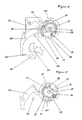
- a quarter distributor 40 designed as a two-armed lever, which is arranged pivotably about an axis 41 parallel to the longitudinal axis of the spring core axis 8.
- the quarter distributor 40 has four consecutively arranged approximately in the circumferential direction of the hour / quarter hour calculator 11 hook openings 42 associated with a quarter of an hour.
- the quarter distributor 40 can be adjusted so that when the hour / quarter hour calculator 11 is turned counterclockwise, the decoupler finger 16 either moves into the first, second, third or fourth hook recess 41, and with further rotation the quarter distributor 40 moves clockwise takes until it comes to rest against a stop 43.
- the decoupler lever 14 located in one of the hook openings 42 with its decoupler finger 16 is pivoted in such a way that it is moved radially outward from the recess 13 with its locking arm 15.
- the position shown in FIG. 6 after the repeater has expired is also the rest position in which the quarter distributor 40 is held against the force of a spring 44 acting on it in abutment against the stop 43.
- the spring core axis 8 rotates clockwise. If the recess 13 and the latch arm 15 overlap, it engages in the recess 13 and the hourly / quarter-hour rake 11 is taken along in a clockwise direction.
- the quarter distributor 40 can pivot counterclockwise by the force applied to the spring 44 until it comes to rest on a step of a quarter-hour scale 46 with a button 45 formed at the free end of its lever opposite the hook openings 42.
- the quarter-hour scale 46 is designed to be driven in a spiral manner about an axis 47 and has three seasons 48, each with four levels of spiraling increasing depth. The drive works through the clockwork with one turn in three hours.
- the button 45 comes to rest on the deepest step, which means that the last hook opening 42 in the direction of movement to the stop 43 is positioned for receiving the decoupler finger 16.
- the button 45 can rest on the highest step and position the first hook opening 42 in the direction of movement to the stop 43 for receiving the decoupler finger 16.
- the second and third hook openings 42 are accordingly positioned when the button 45 is placed on the second or third stage.
- the button 45 Since the button 45 is pivoted out of the area of the quarter-hour relay 46 in the rest position of the revolving mechanism, it can be driven unhindered by the clockwork and rotate.
Landscapes
- Physics & Mathematics (AREA)
- General Physics & Mathematics (AREA)
- Electromechanical Clocks (AREA)
- Measurement Of Unknown Time Intervals (AREA)
Abstract
Description
Die Erfindung bezieht sich auf eine Repetieruhr mit einem Uhrwerk und einer abhängig von der momentanen Stundenstellung des Uhrwerks manuell spannbaren Feder, mit einem Stunden/Viertelstundenrechen, der durch die sich entspannende Feder drehbar antreibbar ist und von dem ein Stundenschöpfer eines Stundenschlagwerks und ein Viertelstundenschöpfer eines Viertelstundenschlagwerks einen Stundenhammer gegen eine Stundentonfeder und einen Viertelstundenhammer gegen eine Viertelstundentonfeder anschlagend schwenkbar antreibbar sind.The invention relates to a repeater watch with a clockwork and a spring that can be tensioned manually depending on the current hour position of the clockwork, with an hour / quarter-hour rake that can be rotatably driven by the relaxing spring and of which an hour creator of an hourly striking mechanism and a quarter-hour creator of a quarter-hourly striking mechanism an hour hammer against an hour spring and a quarter hour hammer against a quarter hour spring can be pivotally driven.
Bei Repetieruhren, insbesondere bei Armbanduhren besteht das Problem, daß aufgrund der begrenzten Baugröße nur wenig Bauraum zur Verfügung steht, um insbesondere das Repetierwerk unterzubringen.The problem with repeater watches, especially wristwatches, is that, due to the limited size, there is little space available to accommodate the repeater mechanism in particular.
Aufgabe der Erfindung ist es daher, eine Repetieruhr der eingangs genannten Art zu schaffen, deren Repetierwerk eine besonders geringe Baugröße aufweist.The object of the invention is therefore to create a repeater clock of the type mentioned, the repeater mechanism has a particularly small size.
Diese Aufgabe wird erfindungsgemäß dadurch gelöst, daß der kreisscheibenartig ausgebildete Stunden/Viertelstundenrechen auf einer Federkernachse frei drehbar gelagert ist, an der die mit ihrem einen Ende ortsfest angeordnete Feder mit ihrem anderen Ende befestigt ist, daß die Federkernachse die Feder spannend manuell in einer Drehrichtung in eine der momentanen Stundenstellung des Uhrwerks entsprechende Winkelposition und von der entspannenden Feder in die andere Drehrichtung drehbar antreibbar ist, mit einer Kupplungsvorrichtung, die bei Antrieb der Federkernachse in Federspannrichtung Federkernachse und Stunden/Viertelstundenrechen drehfest miteinander verbindend einkuppelbar ist, und die bei Antrieb der Federkernachse in Federentspannungsrichtung nach Überwindung eines der momentanen Stunden- und Viertelstundenstellung des Uhrwerks entsprechenden Drehwinkels auskuppelbar ist. Durch diese Ausbildung sind auf der Federkernachse die Bauteile mehrerer Funktionen konzentriert und teilweise in Kombinationsfunktion angeordnet, so daß der erforderliche Bauraum äußerst gering ist. Dies wird noch unterstützt, wenn an der radial umlaufenden Mantelfläche des Stunden/Viertelstundenrechens eine Zahnreihe mit Stundenzähler und eine erste Zahnreihe mit Viertelstundenzähnen ausgebildet ist, wobei durch die Stundenzähne der Stundenschöpfer und durch die Viertelstundenzähne der Viertelstundenschöpfer schwenkbar antreibbar sind.This object is achieved in that the circular disk-shaped hour / quarter-hour rake is freely rotatably mounted on a spring axis on which the spring arranged at one end is fixed at its other end that the spring axis the spring exciting manually in one direction of rotation an angular position corresponding to the current hour position of the clockwork and can be rotatably driven by the relaxing spring in the other direction of rotation, with a coupling device which, when the spring core axis is driven in the spring tensioning direction, can be rotatably connected to the spring core axis and hourly / quarter-hour rake, and which when the spring core axis is driven in Spring release direction can be disengaged after overcoming an angle of rotation corresponding to the current hour and quarter hour position of the clockwork. Through this design, the components of several functions are concentrated on the innerspring axis and partially arranged in a combination function, so that the required installation space is extremely small. This is further supported if a row of teeth with an hour counter and a first row of teeth with quarter-hour teeth are formed on the circumferential circumferential surface of the hourly / quarter-hourly arithmetic, whereby the hour creator and the quarter hour teeth of the quarter hour creator can be pivoted.
Ist an der radial umlaufenden Mantelfläche des Stunden/Viertelstundenrechens eine zweite Zahnreihe mit zweiten Viertelstundenzähnen ausgebildet, durch die der Stundenschöpfer schwenkbar antreibbar ist, so kann das Anschlagen der Viertelstunden mit einem Doppelanschlag erfolgen, wobei hintereinander die Stundentonfeder und die Viertelstundentonfeder oder umgekehrt angschlagen werden.If a second row of teeth with second quarter-hour teeth is formed on the radially circumferential surface of the hour / quarter-hour calculation, by means of which the hour creator can be pivoted, the quarter-hour can be struck with a double stop take place, with the hourly spring and quarter-hourly spring or the other way round.
Vorzugsweis sind die Zähne der Zahnreihen radial hervorstehend ausgebildet.The teeth of the rows of teeth are preferably designed to protrude radially.
Zum Erreichen eines Doppelschlags für die Viertelstunden wird eine besonders geringe Baugröße bei einfachem Aufbau erreicht, wenn hintereinander die Zahnreihe der Stundenzähne, die zweite Zahnreihe der Viertelstundenzähne und die erste Zahnreihe der Viertelstundenzähne angeordnet sind, und bei durch die Feder angetriebenen Stunden/Viertelstundenrechen nach Antrieb des Stundenschöpfers durch die Stunden zähne abwechselnd der Stundenschöpfer durch die Viertelstundenzähne der zweiten Zahnreihe und der Viertelstundenschöpfer durch die Viertelstundenzähne der ersten Zahnreihe schwenkbar antreibbar sind, da dann viele Bauteile in einer Ebene angeordnet sind, was zu geringer Bauhöhe führt.To achieve a double stroke for the quarter hours, a particularly small size is achieved with a simple construction if the row of teeth of the hour teeth, the second row of teeth of the quarter hour teeth and the first row of teeth of the quarter hour teeth are arranged one behind the other, and in the case of spring-driven hour / quarter hour rakes after driving the Hour creator through the hours teeth alternately, the hour creator through the quarter-hour teeth of the second row of teeth and the quarter-hour creator through the quarter-hour teeth of the first row of teeth can be pivoted, since many components are then arranged in one plane, which leads to a low overall height.
Vorzugsweise stehen dabei die Viertelstundenzähne der ersten Zahnreihe radial weiter hervor als die Viertelstundenzähne der zweiten Zahnreihe und die Stundenzähne, wobei Stundenschöpfer und Viertelstundenschöpfer in Umfangsrichtung mit einem Abstand zueinander angeordnet sind, der um einen halben Zahnabstand geringer bzw. größer ist als die zweite Zahnreihe der Viertelstundenzähne.The quarter-hour teeth of the first row of teeth preferably protrude radially further than the quarter-hour teeth of the second row of teeth and the hour teeth, the hour creator and quarter hour creator being arranged in the circumferential direction at a distance from one another which is half a tooth distance smaller or greater than the second row of teeth of the quarter hour teeth .
Die die Anzahl der Viertelstundenschläge bestimmende Kupplungsvorrichtung besitzt einen einfachen Aufbau, wenn die Kupplungsvorrichtung einen um eine zur Längsachse der Federkernachse parallele Schwenkachse schwenkbar am Stunden/Viertelstundenrechen gelagerten Auskupplerhebel aufweist, der federbeaufschlagt mit einem Rastarm etwa radial in eine entsprechende Ausnehmung der Federkernachse einrastbar und mittels eines hakenartigen Viertelverteilers aus der Ausnehmung herausschwenkbar ist.The coupling device determining the number of quarter-hour beats has a simple structure, if the coupling device has a decoupling lever which is pivotably mounted on the hourly / quarter-hour rake about a pivot axis parallel to the longitudinal axis of the spring core axis and which, when spring-loaded, can be latched approximately radially into a corresponding recess in the spring core axis and pivoted out of the recess by means of a hook-like quarter distributor.
Dabei kann der Auskupplerhebel einen etwa radial hervorstehenden Auskupplerfinger besitzen, der nach Überwindung eines etwa den momentanen Stunden des Uhrwerks entsprechenden Drehwinkels des durch die entspannende Feder angetriebenen Stunden/Viertelstundenrechens in eine der jeweiligen Viertelstunde entsprechende Hakenöffnung des Viertelverteilers eingreifbar ist und durch diesen nach Überwindung eines weiteren durch die momentane Viertelstunde bestimmten Drehwinkels die weitere Drehbewegung des Stunden/Viertelstundenrechens blockierend den Rastarm aus der Ausnehmung ausrastend schwenkbar beaufschlagbar ist.The decoupling lever can have an approximately radially protruding decoupling finger which, after overcoming an angle of rotation corresponding to the current hours of the clockwork of the hour / quarter hour calculation driven by the relaxing spring, can be engaged in a hook opening of the quarter distributor corresponding to the respective quarter hour and by overcoming another by the current quarter-hour determined angle of rotation, the further rotary movement of the hourly / quarter-hour arithmetic blocking the latching arm can be acted upon by disengaging the recess.
Eine Anordnung weitgehend in einer Ebene und damit eine geringe Bauhöhe wird erreicht, wenn der Viertelverteiler ein um eine zur Längsachse der Federkernachse parallele Achse schwenkbarer Hebel ist, der an seinem einen freien Ende vier etwa in Umfangsrichtung des Stunden/Viertelstundenrechens hintereinander angeordnete, jeweils einer Viertelstunde zugeordnete Hakenöffnungen aufweist, wobei der Viertelverteiler in eine Position schwenkbar einstellbar ist, in der die der momentanen Viertelstunde zugeordnete Hakenöffnung in den Umlaufbereich des Auskupplerfingers diesen aufnehmbar ragt, und wobei der Schwenkweg des von dem in die Hakenöffnung eingreifenden Auskupplerfingers schwenkend bewegten Viertelverteilers in der Ausrastposition des Rastarms aus der Ausnehmung durch einen Anschlag begrenzt ist.An arrangement largely in one plane and thus a low overall height is achieved if the quarter distributor is a lever which can be pivoted about an axis parallel to the longitudinal axis of the spring core axis and which, at its one free end, four successively arranged in the circumferential direction of the hour / quarter hour calculation, each one quarter of an hour has associated hook openings, the quarter distributor being pivotally adjustable into a position in which the hook opening assigned to the current quarter hour protrudes into the circumferential area of the decoupler finger, and wherein the swivel path of the in the hook opening engaging decoupler finger pivotally moved quarter distributor in the disengaged position of the locking arm is limited by a stop.
Zur Bestimmung der jeweils anzuschlagenden Viertelstunden kann der Viertelverteiler entgegen der Schwenkbewegung zum Anschlag bis zur Anlage eines an ihm angeordneten Tasters an einer vom Uhrwerk drehbar antreibbaren Viertelstundenstaffel schwenkbar sein, die spiralartig in Umfangsrichtung hintereinander vier bzw. ein Mehrfaches von vier Stufen aufweist, wobei bei Anlage des Tasters an einer Stufe die diese Stufe entsprechende Hakenöffnung in den Umlaufbereich des Auskuppelfingers geschwenkt ist.In order to determine the quarter hours to be struck in each case, the quarter distributor can be pivoted counter to the pivoting movement to the stop until a pushbutton arranged on it can be pivoted on a quarter hour scale which can be driven by the clockwork and which has four or a multiple of four stages in a spiral in the circumferential direction, with system of the button on a step the hook opening corresponding to this step is pivoted into the circulation area of the disengaging finger.
Zur Sicherstellung der Einnahme der abzutastenden Position ist der Viertelverteiler vorzugsweise zur Anlage des Tasters an der Viertelstundenstaffel federbeaufschlagt.To ensure that the position to be scanned is taken up, the quarter distributor is preferably spring-loaded in order to rest the button on the quarter-hour scale.
Ein Ausführungsbeispiel der Erfindung ist in der Zeichnung dargestellt und wird im folgenden näher beschrieben. Es zeigen
Figur 1- eine Draufsicht auf das Repetierwerk einer Repetieruhr,
Figur 2- eine Draufsicht auf die Baugruppe Aufzugshebel, Feder und Federkernachse der Repetieruhr nach
Figur 1, Figur 3- eine Draufsicht auf Stundenschlagwerk und Stundenhammer der Repetieruhr nach
Figur 1, Figur 4- einen Querschnitt der Baugruppe der auf der Federkernachse angeordneten Bauteile der Repetieruhr nach
Figur 1, Figur 5- eine Draufsicht auf Viertelverteiler und Viertelstundenstaffel der Repetieruhr nach
Figur 1 in Abtaststellung, - Figur 6
- eine Draufsicht der Baugruppe Viertelverteiler, Viertelstundenstaffel, Stunden/Viertelstundenrechen der Repetieruhr nach
Figur 1 in abgelaufener Stellung, - Figur 7
- eine Draufsicht auf Viertelverteiler und Stunden/Viertelstundenrechen in Aufzugsbetätigung,
Figur 8- eine Draufsicht auf Viertelverteiler und Stunden/Viertelstundenrechen in Ablauffunktion,
Figur 9- eine Draufsicht auf Stunden/Viertelstundenrechen sowie Stundenschöpfer und Viertelstundenschöpfer in Ablauffunktion.
- Figure 1
- a plan view of the repeater of a repeater watch,
- Figure 2
- 2 shows a plan view of the assembly of the elevator lever, spring and spring core axis of the repeater watch according to FIG. 1,
- Figure 3
- 2 shows a top view of the hourly striking mechanism and hour hammer of the repeater clock according to FIG. 1,
- Figure 4
- 2 shows a cross section of the assembly of the components of the repeater clock according to FIG. 1 arranged on the spring core axis,
- Figure 5
- 2 shows a plan view of the quarter distributor and quarter hour scale of the repeater clock according to FIG. 1 in the scanning position,
- Figure 6
- 2 shows a top view of the assembly of the quarter distributor, quarter hour scale, hour / quarter hour rake of the repeater clock according to FIG. 1 in the expired position,
- Figure 7
- a top view of quarter distributor and hour / quarter hour rake in elevator operation,
- Figure 8
- a top view of quarter distributors and hours / quarter hour calculations in the sequence function,
- Figure 9
- a top view of hour / quarter hour rake and hour creator and quarter hour creator in sequence function.
Die dargestellte Repetieruhr besitzt einen in Figur 1 nicht erkennbaren Aufzugshebel 1, der um eine Achse 2 schwenkbar angeordnet ist. Durch manuelle Beaufschlagung eines Nockens 3 ist der Aufzugshebel 1 bis zur Anlage eines an ihm angeordneten Anschlagstifts 4 an einer Stundenstaffel 5 schwenkbar.
Die Stundenstaffel 5 ist spiralartig mit zwölf Stufen ausgebildet und wird von einem nicht dargestellten Uhrwerk mit einer Umdrehung in 12 Stunden drehbar angetrieben. Entsprechend der Stufen kann somit der Aufzugshebel 1 mehr oder weniger verschwenkt werden.The repeater watch shown has an
The
Konzentrisch zur Achse 2 ist am Aufzugshebel 1 ein Zahnsegment 6 ausgebildet, das in die Zähne eines Aufzugtriebrades 7 eingreift. Das Aufzugtriebrad 7 ist auf einer drehbar gelagerten Federkernachse 8 fest angeordnet. Ebenfalls fest mit der Federkernachse 8 verbunden ist das eine Ende einer spiralförmig die Federkernachse 8 umschließenden Zugfeder 9, deren anderes Ende an einem feststehenden Federhaus 10 befestigt ist.A toothed segment 6, which engages in the teeth of an elevator drive wheel 7, is formed on the
Durch Verschwenken des Aufzugshebels 1 gegen den Uhrzeigersinn wird das Aufzugtriebrad 7 und damit die Federkernachse 8 entsprechend der momentanen Stunde des Uhrwerks gedreht und damit entsprechend die Zugfeder gespannt.By pivoting the elevator lever 1 counterclockwise, the elevator drive wheel 7 and thus the
Wie in Figur 4 zu erkennen ist, ist auf der Federkernachse 8 frei drehbar ein Stunden/Viertelstundenrechen 11 gelagert, neben dem wiederum eine kreisförmige Mitnehmerscheibe 12 drehfest auf der Federkernachse 8 angeordnet ist, die eine radial nach außen offene Ausnehmung 13 aufweist.As can be seen in FIG. 4, an hourly / quarter-
Auf dem kreisscheibenartig ausgebildeten Stunden/Viertelstundenrechen 11 ist in gleicher Ebene wie die Mitnehmerscheibe 12 ein Auskupplerhebel 14 schwenkbar gelagert, dessen einer freier Hebelarm einen Rastarm 15 bildet, der etwa radial in die Ausnehmung 13 einrastbar ist und so den Stunden/Viertelstundenrechen 11 drehfest mit der Mitnehmerscheibe 12 und der Federkernachse 8 verbindet.On the circular disk-shaped hour / quarter-
Weiterhin besitzt der Auskupplerhebel 14 einen etwa radial hervorstehenden Auskupplerfinger 16, mittels dessen der Auskupplerhebel 14 so verschwenkt werden kann, daß der Rastarm 15 aus der Ausnehmung 13 herausschwenkt.Furthermore, the
Durch eine auf dem Stunden/Viertelstundenrechen 11 angeordnete Auskupplerfeder 17 ist der Auskupplerhebel 14 mit seinem Rastarm 15 gegen die radial umlaufende zylindrische Mantelfläche der Mitnehmerscheibe 12 beaufschlagt und rastet so mit dem Rastarm 15 in die Ausnehmung 13 ein, wenn Rastarm 15 und Ausnehmung 13 in Überdeckung gelangen.By means of a decoupling
An der radial umlaufenden Mantelfläche des Stunden/Viertelrechens 11 ist im Uhrzeigersinn hintereinander mit radial hervorstehenden Zähnen eine Zahnreihe mit zwölf Stundenzähnen 18, eine zweite Zahnreihe mit drei Viertelstundenzähnen 19 und eine erste Zahnreihe mit drei Viertelstundenzähnen 20 angeordnet. Dabei ragen die Stundenzähne 18 und die Viertelstundenzähne 19 gleich weit radial hervor, während die Viertelstundenzähne 20 etwas weiter radial hervorstehen als die anderen Zähne.A row of teeth with twelve
Wie sowohl in Figur 1 als auch in Figur 9 zu sehen ist, können bei einer von der sich entspannenden Zugfeder 9 erzeugter Drehbewegung des Stunden/Viertelstundenrechens 11 entgegen dem Uhrzeigersinn die Stundenzähne 18 und Viertelstundenzähne 19 über eine Mitnehmernase 21 einen Stundenschöpfer 22 und die Viertelstundenzähne 20 über eine Mitnehmernase 23 einen Viertelstundenschöpfer 24 entgegen einer Federkraft verschwenken.As can be seen both in FIG. 1 and in FIG. 9, when the hour /
Durch die Schwenkbewegung des Stundenschöpfers 22 ist ein Zwischenhebel 25 um eine Achse 26 schwenkbar, der wiederum an einem schwenkbaren Stundenhammerhebel 27 angreift und diesen entgegen der Kraft einer Feder 28 mit seinem Stundenhammer 29 von einer Stundentonfeder 30 abhebt.Due to the pivoting movement of the
Ist die Spitze eines Stundenzahnes 18 bzw. Viertelstundenzahns 19 am Ende der Schwenkbewegung des Stundenschöpfers 22 über dessen Mitnehmernase 21 gerastet, schwenken Stundenschöpfer 22, Zwischenhebel 25 und Stundenhammerhebel 27 zurück und der Stundenhammer 29 schlägt mit Schwung auf die Stundentonfeder 30 auf, so daß ein Ton erzeugt wird.If the tip of an
Auf die gleiche Weise wird durch einen Viertelstundenzahn 20 der Viertelstundenschöpfer 24 verschwenkt, der diese Bewegung wiederum über einen um die Achse 31 schwenkbaren Zwischenhebel 32 auf einen schwenkbaren Viertelstundenhammerhebel 33 überträgt, an dessen Ende ein Viertelstundenhammer 34 angeordnet ist. Dieser wird dabei von einer Viertelstundentonfeder 35 entgegen der Kraft einer Feder 36 abgehoben. Nach Überrasten der Mitnehmernase 23 durch den Viertelstundenzahn 20 erfolgt mit Schwung das Aufschlagen des Viertelstundenhammers 34 auf der Viertelstundentonfeder 35, die einen höheren Ton erzeugt als die Stundentonfeder 30.In the same way, the quarter-
Auf der Achse 31 ist darüber hinaus neben dem Viertelstundenschöpfer 4 auch ein Minutenschöpfer 37 gelagert, der von einem Minutenrechen 38 mit vierzehn Minutenzähnen 39 schwenkbar antreibbar ist und der ebenfalls über den Zwischenhebel 32 und den Viertelstundenhammer 33 den Viertelstundenhammer 34 zum Anschlagen an der Viertelstundentonfeder 35 antreibt.In addition to the quarter-
Stundenschöpfer 22 und Viertelstundenschöpfer 24 sind in Umfangsrichtung hintereinander mit einem Abstand angeordnet, der um einen halben Zahnabstand größer ist aals die Zahnreihe der Viertelstundenzähne 19. Außerdem ist der Abstand des Viertelstundenschöpfers 24 von dem Stunden/Viertelstundenrechen 11 so groß, daß dieser nicht von den Stundenzähnen 18 und den Viertelstundenzähnen 19 sondern nur von den Viertelstundenzähnen 20 schwenkbar antreibbar ist.
Dies führt dazu, daß zum Anschlagen der Viertelstunden ein Doppelanschlag durchgeführt wird, bei dem zuerst durch einen Viertelstundenzahn 20 ein Anschlag der Minutentonfeder 35 und dann zeitlich dazu versetzt durch einen Viertelstundenzahn 19 ein Anschlag der Stundentonfeder 30 ausgelöst wird.This leads to the fact that a double stop is carried out for striking the quarter hours, in which a stop of the
Zur Bestimmung der Anzahl der auszulösenden Viertelstundenschläge ist ein als zweiarmiger Hebel ausgebildeter Viertelverteiler 40 vorhanden, der um eine zur Längsachse der Federkernachse 8 parallel Achse 41 schwenkbar angeordnet ist.To determine the number of quarter-hour strikes to be triggered, there is a
An dem freien Ende seines der Federkernachse 8 zugewandten Hebelarms, der sich in der Ebene des Auskupplerhebels 14 befindet, besitzt der Viertelverteiler 40 vier etwa in Umfangsrichtung des Stunden/Viertelstundenrechens 11 hintereinander angeordnete, jeweils einer Viertelstunde zugeordnete Hakenöffnungen 42.At the free end of its lever arm which faces the
Durch unterschiedliches Verschwenken ist der Viertelverteiler 40 so einstellbar, daß bei Drehen des Stunden/Viertelstundenrechens 11 entgegen dem Uhrzeigersinn der Auskupplerfinger 16 entweder in die erste, die zweite, die dritte oder die vierte Hakenausnehmung 41 hineinfährt und bei weiterer Drehung dadurch den Viertelverteiler 40 im Uhrzeigersinn mitnimmt, bis dieser zur Anlage an einen Anschlag 43 kommt.By pivoting differently, the
Bis zu diesem Zeitpunkt ist der Stunden/Viertelstundenrechen 11 über die Mitnehmerscheibe 12 mit der Federkernachse 8 drehfest gekuppelt.Up to this point, the hourly / quarter-
Nach Anlage des Viertelverteilers 40 am Anschlag 43 wird der mit seinem Auskupplerfinger 16 in einer der Hakenöffnungen 42 befindliche Auskupplerhebel 14 derart verschwenkt, daß er mit seinem Rastarm 15 aus der Ausnehmung 13 radial nach außen bewegt wird.After the
Damit bleibt der Stunden/Viertelstundenrechen 11 stehen, während sich die Federkernachse 8 noch so weit weiterdreht, bis sie ihre ursprüngliche Ausgangsposition vor dem Spannen der Zugfeder 9 wieder erreicht hat.This stops the hour /
Greift der Auskupplerfinger 16 in die in Bewegungsrichtung zum Anschlag 43 erste Hakenöffnung 42 ein, so können bis zum Erreichen des Anschlags 43 und Lösen des Rastarms 15 aus der Ausnehmung 13 keine Viertelstundenzähne 19 und 20 in den Bereich der ihnen zugeordneten Schöpfer gelangen und einen Viertelstundenschlag auslösen. Dies ist der Fall, wenn das Uhrwerk sich in der ersten Viertelstunde einer Stunde befindet.If the
Kommt jedoch der Auskopplerfinger 16 in die in Bewegungsrichtung zum Anschlag 43 letzte Hakenöffnung zum Eingriff, bleibt die drehfeste Kupplung zwischen Federkernachse 8 und Stunden/Viertelstundenrechen 11 über einen längeren Drehweg bis zum Erreichen des Anschlags 43 durch den Viertelverteiler 40 bestehen, so daß alle drei Viertelstundenzähne 19 und 20 Viertelstundenanschläge auslösen. Dies ist der Fall, wenn das Uhrwerk sich in der vierten Viertelstunde einer Stunde befindet.However, if the
Die in Figur 6 dargestellte Position nach Ablauf des Repetitionswerks ist auch die Ruheposition, in der der Viertelverteiler 40 entgegen der Kraft einer ihn beaufschlagenden Feder 44 in Anlage am Anschlag 43 gehalten wird.The position shown in FIG. 6 after the repeater has expired is also the rest position in which the
Erfolgt ein Aufziehen des Repetitionswerkes, so dreht sich die Federkernachse 8 im Uhrzeigersinn. Bei Überdeckung von Ausnehmung 13 und Rastarm 15 rastet dieser in die Ausnehmung 13 ein und der Stunden/Viertelstundenrechen 11 wird im Uhrzeigersinn mitgenommen.If the repeater is pulled open, the
Damit kann der Viertelverteiler 40 durch die Kraftbeaufschlagung der Feder 44 entgegen dem Uhrzeigersinn verschwenken, bis er mit einem am freien Ende seines, den Hakenöffnungen 42 entgegengesetzten Hebels ausgebildeten Tasters 45 an einer Stufe einer Viertelstundenstaffel 46 zur Anlage kommt.Thus, the
Die Viertelstundenstaffel 46 ist spiralartig um eine Achse 47 drehbar angetrieben ausgebildet und besitzt drei Staffeln 48 mit jeweils vier Stufen spiralartig ansteigender Tiefe. Der Antrieb erfogt durch das Uhrwerk mit einer Umdrehung in drei Stunden.The quarter-
Während der vierten Viertelstunde einer Stunde kommt der Taster 45 auf der tiefsten Stufe zur Anlage, was bedeutet, daß die in Bewegungsrichtung zum Anschlag 43 letzte Hakenöffnung 42 zur Aufnahme des Auskupplerfingers 16 positioniert ist.During the fourth quarter of an hour, the
Während der ersten Viertelstunde kann der Taster 45 auf der höchsten Stufe aufliegen und die in Bewegungsrichtung zum Anschlag 43 erste Hakenöffnung 42 zur Aufnahme des Auskupplerfingers 16 positionieren. Entsprechend erfolgt bei Auflage des Tasters 45 auf der zweiten bzw. dritten Stufe eine Positionierung der zweiten und dritten Hakenöffnung 42.During the first quarter of an hour, the
Da in der Ruhestellung des Revesierwerkes der Taster 45 aus dem Bereich der Viertelstundenstaffel 46 herausgeschwenkt ist, kann diese ungehindert vom Uhrwerk angetrieben, sich drehen.Since the
Claims (11)
Applications Claiming Priority (2)
| Application Number | Priority Date | Filing Date | Title |
|---|---|---|---|
| DE4012028A DE4012028A1 (en) | 1990-04-13 | 1990-04-13 | REPEATING WATCH |
| DE4012028 | 1990-04-13 |
Publications (2)
| Publication Number | Publication Date |
|---|---|
| EP0451338A1 true EP0451338A1 (en) | 1991-10-16 |
| EP0451338B1 EP0451338B1 (en) | 1993-12-15 |
Family
ID=6404381
Family Applications (1)
| Application Number | Title | Priority Date | Filing Date |
|---|---|---|---|
| EP90122017A Expired - Lifetime EP0451338B1 (en) | 1990-04-13 | 1990-11-17 | Repeating watch |
Country Status (2)
| Country | Link |
|---|---|
| EP (1) | EP0451338B1 (en) |
| DE (2) | DE4012028A1 (en) |
Citations (7)
| Publication number | Priority date | Publication date | Assignee | Title |
|---|---|---|---|---|
| US383260A (en) * | 1888-05-22 | walzee | ||
| CH6099A (en) * | 1893-01-04 | 1893-08-15 | Mathey Tissot E | Advanced quarter-repeater watch |
| CH7894A (en) * | 1894-01-18 | 1894-08-15 | Z Pantillon | Grand strike and repeater watch |
| CH9962A (en) * | 1895-03-29 | 1895-10-31 | Aubert George | Mechanism regulating the striking of the quarters and minutes in repeating watches so as to eliminate the silences of variable length which separate the striking of the hours from that of the quarters or minutes |
| CH14007A (en) * | 1897-04-05 | 1897-09-30 | Freres Reymond | Simplified minute repeater mechanism |
| CH16382A (en) * | 1898-04-30 | 1898-11-30 | Marchand & Sandoz | Advanced repeater watch mechanism |
| DE412846C (en) * | 1925-04-28 | Kramer Carl | Repetitive striking mechanism for watches, the sequence of which is regulated by the mechanism |
-
1990
- 1990-04-13 DE DE4012028A patent/DE4012028A1/en not_active Ceased
- 1990-11-17 DE DE90122017T patent/DE59003898D1/en not_active Expired - Fee Related
- 1990-11-17 EP EP90122017A patent/EP0451338B1/en not_active Expired - Lifetime
Patent Citations (7)
| Publication number | Priority date | Publication date | Assignee | Title |
|---|---|---|---|---|
| US383260A (en) * | 1888-05-22 | walzee | ||
| DE412846C (en) * | 1925-04-28 | Kramer Carl | Repetitive striking mechanism for watches, the sequence of which is regulated by the mechanism | |
| CH6099A (en) * | 1893-01-04 | 1893-08-15 | Mathey Tissot E | Advanced quarter-repeater watch |
| CH7894A (en) * | 1894-01-18 | 1894-08-15 | Z Pantillon | Grand strike and repeater watch |
| CH9962A (en) * | 1895-03-29 | 1895-10-31 | Aubert George | Mechanism regulating the striking of the quarters and minutes in repeating watches so as to eliminate the silences of variable length which separate the striking of the hours from that of the quarters or minutes |
| CH14007A (en) * | 1897-04-05 | 1897-09-30 | Freres Reymond | Simplified minute repeater mechanism |
| CH16382A (en) * | 1898-04-30 | 1898-11-30 | Marchand & Sandoz | Advanced repeater watch mechanism |
Also Published As
| Publication number | Publication date |
|---|---|
| DE4012028A1 (en) | 1991-10-17 |
| EP0451338B1 (en) | 1993-12-15 |
| DE59003898D1 (en) | 1994-02-03 |
Similar Documents
| Publication | Publication Date | Title |
|---|---|---|
| EP3070543A1 (en) | Repetition striking mechanism with integrated trigger lock | |
| DE60205763T2 (en) | Timepiece provided with striking mechanism | |
| DE2929091A1 (en) | PERFORMANCE FOR A CLOCK | |
| DE3323420C2 (en) | Striking mechanism clock with device to switch off the striking mechanism | |
| EP0451338B1 (en) | Repeating watch | |
| EP0451334B1 (en) | Repeating watch | |
| EP0451341B1 (en) | Repeating watch | |
| EP1367463B1 (en) | Timepiece | |
| EP0451337B1 (en) | Repeating watch | |
| EP0451336B1 (en) | Mainspring assembly | |
| DE502153C (en) | Clock with independent movement, hour, half-hour and quarter-hour striking mechanism | |
| WO2024032926A1 (en) | Timepiece having a quarter repeater and an hour repeater | |
| DE576311C (en) | Clock mechanism with self-regulation | |
| DE675105C (en) | Device for controlling electric motor-operated tower clock strikes | |
| DE68781C (en) | Inductor clock with multiple times | |
| DE2826869C3 (en) | Programmer for electrical household appliances | |
| DE632253C (en) | Alarm clock with triggering of the signal mechanism at different times | |
| DE1673623C (en) | Triggering device for repeating alarm clocks | |
| DE112110C (en) | ||
| DE524780C (en) | Clock with striking mechanism | |
| DE19165C (en) | Innovations in watch movements. C. | |
| DE4322471A1 (en) | Clock | |
| DE2242091C3 (en) | Device for setting a parking meter | |
| DE12637C (en) | Innovations in repeater watches | |
| DE100402C (en) |
Legal Events
| Date | Code | Title | Description |
|---|---|---|---|
| PUAI | Public reference made under article 153(3) epc to a published international application that has entered the european phase |
Free format text: ORIGINAL CODE: 0009012 |
|
| 17P | Request for examination filed |
Effective date: 19910711 |
|
| AK | Designated contracting states |
Kind code of ref document: A1 Designated state(s): CH DE FR IT LI |
|
| 17Q | First examination report despatched |
Effective date: 19921019 |
|
| GRAA | (expected) grant |
Free format text: ORIGINAL CODE: 0009210 |
|
| AK | Designated contracting states |
Kind code of ref document: B1 Designated state(s): CH DE FR IT LI |
|
| PG25 | Lapsed in a contracting state [announced via postgrant information from national office to epo] |
Ref country code: IT Free format text: LAPSE BECAUSE OF FAILURE TO SUBMIT A TRANSLATION OF THE DESCRIPTION OR TO PAY THE FEE WITHIN THE PRESCRIBED TIME-LIMIT;WARNING: LAPSES OF ITALIAN PATENTS WITH EFFECTIVE DATE BEFORE 2007 MAY HAVE OCCURRED AT ANY TIME BEFORE 2007. THE CORRECT EFFECTIVE DATE MAY BE DIFFERENT FROM THE ONE RECORDED. Effective date: 19931215 |
|
| ET | Fr: translation filed | ||
| REF | Corresponds to: |
Ref document number: 59003898 Country of ref document: DE Date of ref document: 19940203 |
|
| PLBE | No opposition filed within time limit |
Free format text: ORIGINAL CODE: 0009261 |
|
| STAA | Information on the status of an ep patent application or granted ep patent |
Free format text: STATUS: NO OPPOSITION FILED WITHIN TIME LIMIT |
|
| 26N | No opposition filed | ||
| PG25 | Lapsed in a contracting state [announced via postgrant information from national office to epo] |
Ref country code: FR Effective date: 19950731 |
|
| PG25 | Lapsed in a contracting state [announced via postgrant information from national office to epo] |
Ref country code: DE Effective date: 19950801 |
|
| REG | Reference to a national code |
Ref country code: FR Ref legal event code: ST |
|
| PGFP | Annual fee paid to national office [announced via postgrant information from national office to epo] |
Ref country code: CH Payment date: 19981023 Year of fee payment: 9 |
|
| PG25 | Lapsed in a contracting state [announced via postgrant information from national office to epo] |
Ref country code: CH Free format text: LAPSE BECAUSE OF NON-PAYMENT OF DUE FEES Effective date: 19991130 Ref country code: LI Free format text: LAPSE BECAUSE OF NON-PAYMENT OF DUE FEES Effective date: 19991130 |
|
| REG | Reference to a national code |
Ref country code: CH Ref legal event code: PL |