EP0451272A1 - Electrohydraulic proportional control valve - Google Patents
Electrohydraulic proportional control valve Download PDFInfo
- Publication number
- EP0451272A1 EP0451272A1 EP90901020A EP90901020A EP0451272A1 EP 0451272 A1 EP0451272 A1 EP 0451272A1 EP 90901020 A EP90901020 A EP 90901020A EP 90901020 A EP90901020 A EP 90901020A EP 0451272 A1 EP0451272 A1 EP 0451272A1
- Authority
- EP
- European Patent Office
- Prior art keywords
- control valve
- spool valve
- spool
- solenoid
- valve
- Prior art date
- Legal status (The legal status is an assumption and is not a legal conclusion. Google has not performed a legal analysis and makes no representation as to the accuracy of the status listed.)
- Withdrawn
Links
Images

Classifications
-
- F—MECHANICAL ENGINEERING; LIGHTING; HEATING; WEAPONS; BLASTING
- F16—ENGINEERING ELEMENTS AND UNITS; GENERAL MEASURES FOR PRODUCING AND MAINTAINING EFFECTIVE FUNCTIONING OF MACHINES OR INSTALLATIONS; THERMAL INSULATION IN GENERAL
- F16K—VALVES; TAPS; COCKS; ACTUATING-FLOATS; DEVICES FOR VENTING OR AERATING
- F16K31/00—Actuating devices; Operating means; Releasing devices
- F16K31/02—Actuating devices; Operating means; Releasing devices electric; magnetic
- F16K31/06—Actuating devices; Operating means; Releasing devices electric; magnetic using a magnet, e.g. diaphragm valves, cutting off by means of a liquid
- F16K31/0603—Multiple-way valves
- F16K31/061—Sliding valves
- F16K31/0613—Sliding valves with cylindrical slides
-
- F—MECHANICAL ENGINEERING; LIGHTING; HEATING; WEAPONS; BLASTING
- F16—ENGINEERING ELEMENTS AND UNITS; GENERAL MEASURES FOR PRODUCING AND MAINTAINING EFFECTIVE FUNCTIONING OF MACHINES OR INSTALLATIONS; THERMAL INSULATION IN GENERAL
- F16K—VALVES; TAPS; COCKS; ACTUATING-FLOATS; DEVICES FOR VENTING OR AERATING
- F16K31/00—Actuating devices; Operating means; Releasing devices
- F16K31/02—Actuating devices; Operating means; Releasing devices electric; magnetic
- F16K31/06—Actuating devices; Operating means; Releasing devices electric; magnetic using a magnet, e.g. diaphragm valves, cutting off by means of a liquid
-
- Y—GENERAL TAGGING OF NEW TECHNOLOGICAL DEVELOPMENTS; GENERAL TAGGING OF CROSS-SECTIONAL TECHNOLOGIES SPANNING OVER SEVERAL SECTIONS OF THE IPC; TECHNICAL SUBJECTS COVERED BY FORMER USPC CROSS-REFERENCE ART COLLECTIONS [XRACs] AND DIGESTS
- Y10—TECHNICAL SUBJECTS COVERED BY FORMER USPC
- Y10T—TECHNICAL SUBJECTS COVERED BY FORMER US CLASSIFICATION
- Y10T137/00—Fluid handling
- Y10T137/8593—Systems
- Y10T137/86493—Multi-way valve unit
- Y10T137/86574—Supply and exhaust
- Y10T137/86622—Motor-operated
Definitions
- the present invention relates to an electrohydraulic proportional or directional control valve to a solenoid of which is supplied an electric current so as to control the pressure of a pressure oil supplied to an output side of the control valve.
- a sleeve-like element 3 is slidably mounted in a valve bore 2 formed in a valve body 1 of the control valve.
- an inlet port 4 and a drain port 5 are formed in the sleeve-like element 3 in the sleeve-like element 3.
- the sleeve-like element 3 has its front-end interior portion 3a communicate with an outlet port 6 formed in the valve body 1 of the control valve.
- a spool valve 7 is slidably mounted in the sleeve-like element 3.
- spool valve 7 In the spool valve 7 are formed: an axial bore 8; and a radial port 9 which communicates with the axial bore 8 and is formed in a small-diameter portion 7a of the spool valve 7.
- a compression spring 10 is provided to spring bias the spool valve 7 into a position in which: an area defined between the sleeve-like element 3 and the small-diameter portion 7a of the spool valve 7 communicates with the drain port 5; and a moving rod 11a of a solenoid 11, which rod 11a is oppositely disposed from the spool valve 7, abuts on a base-end surface of the spool valve 7.
- the solenoid 11 When an electric current is supplied to the solenoid 11 to energize the same, the solenoid 11 has the moving rod 11a thereof move leftward as viewed in Fig. 1 so that the spool valve 7 is pushed leftward by the moving rod 11a of the solenoid 11 to reach a position in which an area defined between the sleeve-like element 3 and the small-diameter portion 7a of the spool valve 7 communicates with the inlet port 4, whereby the pressure oil supplied from a hydraulic pump P is supplied to the outlet port 6 through: the inlet port 4; the area defined between the sleeve-like element 3 and the small-diameter portion 7a of the spool valve 7; radial port 9; axial bore 8; and the front-end interior portion 3a of the sleeve-like element 3.
- the control valve having the above construction is well known.
- the spool valve 5 moves into a position in which: the area defined between the sleeve-like element 3 and the small-diameter portion 7a of the spool valve 7 communicates with the drain port 5; and the outlet port 6 communicates with a reservoir 12, so that no pressure exists in the outlet port 6.
- air exists in an outlet-side passage of a hydraulic circuit of the control valve, such air is compressed when the solenoid 11 is energized to press its moving rod 11a against the spool valve 7 so as to have a pressure of the pressure oil in the outlet port build up to a predetermined level. consequently, such compression of air considerably impairs the control valve in responsibility.
- the spool valve 7 takes too much time until the area defined between the sleeve-like element 3 and the small-diameter portion 7a of the spool valve 7 reaches a position in which the area communicates with the inlet port 4, and, therefore, in this respect, the conventional control valve is further impaired in responsibility.
- the present invention was made. Consequently, it is an object of the present invention to provide an electrohydraulic proportional control valve which is improved in responsibility: by always pressurizing a pressure oil supplied to an outlet-side passage of a hydraulic circuit of the control valve to prevent air from entering the outlet-side passage; and by moving a spool valve of the control valve without causing any time delay when a solenoid of the control valve is energized.
- An electrohydraulic proportional control valve comprising in combination: a spool valve for permitting/preventing communication between: an inlet port communicating with a hydraulic pump disposed in a hydraulic circuit of the control valve; and an outlet port communicating with an outlet-side passage of the hydraulic circuit; a spring means for applying a spring force to a base-end surface of the spool valve so as to have the spring force balance a hydraulic force applied to a front-end surface of the spool valve so that the spool valve is held at a position in which the inlet port slightly communicates with the outlet port; and a solenoid provided with a moving rod oppositely disposed from the base-end surface of the spool valve, the solenoid being so energized as to move the spool valve into a position in which the inlet port completely communicates with the outlet port.
- the moving rod of the solenoid loses its pressing force against the spool valve to permit the spool valve to move, under the influence of a spring force exerted by the spring means, into a spring-force/hydraulic-force balanced position in which the inlet port slightly communicates with the outlet port and be held at the position, so that: air is prevented from entering the outlet-side passage of the hydraulic circuit of the control valve; and the spool valve of the control valve is operated without causing any time delay whenever the solenoid of the control valve is energized, whereby the control valve of the present invention is improved in responsibility.
- a spring shoe 20 is provided in the base-end side of the spool valve 7 so that: a first spring 21 is interposed between the spring shoe 20 and a flange portion 7b of the spool valve 7; and a second spring 22 is interposed between the spring shoe 20 and the sleeve-like element 3, whereby the spring shoe 20 abuts on a stopper 23.
- the spool valve 7 is constantly biased leftward as viewed in Fig. 2 by the first spring 21 to move into a position in which the inlet port 4 slightly communicates with the area defined between the sleeve-like element 3 and the small-diameter portion 7a of the spool valve 7.
- the moving rod 11a of the solenoid 11 separates from the spring shoe 20.
- the first spring 21 is set so that the spring force exerted by the first spring 21 to act on the base-end surface of the spool valve 7 balances the hydraulic force acting on the front-end surface of the spool valve 7 at a position in which the inlet port 4 slightly communicates with the outlet port 6 when no electric current is supplied to the solenoid 11 of the control valve.
- the pressure of the pressure oil supplied to the outlet-side passage of the hydraulic circuit of the control valve has a value P o .
- the spring shoe 20 is pushed by the moving rod 11a of the solenoid 11.
- the spring shoe 20 abuts on the base-end surface of the spool valve 7, and pushes the spool valve 7 leftward as viewed in Fig.
Abstract
This invention relates to an electrohydraulic proportional control valve which fills always pressure oil into an oil path on the output side to prevent the existence of air therein, can move a spool without any time delay when a solenoid is energized and thus improves response. The hydraulic proportional control valve includes a spool (7) which establishes cuts off communication between an inlet port (4) communicating with a hydraulic pump (P) and an outlet port (6) on the output side, a spring disposed in such a manner as to apply to the base end of the spool such a spring force, which is in equilibrium with the oil pressure force acting on the tip of the spool so as to keep the spool at the position where the inlet port and the outlet port slightly communicate with each other, and a moving rod (11a) disposed in such a manner as to oppose the base end of the spool. The control valve includes further a solenoid (11) which biases the spool in a direction in which the inlet port and the outlet port communicate completely with each other.
Description
- The present invention relates to an electrohydraulic proportional or directional control valve to a solenoid of which is supplied an electric current so as to control the pressure of a pressure oil supplied to an output side of the control valve.
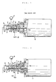
- In a conventional electrohydraulic proportional or directional control valve, as shown in Fig. 1, a sleeve-
like element 3 is slidably mounted in avalve bore 2 formed in a valve body 1 of the control valve. In the sleeve-like element 3 are formed aninlet port 4 and adrain port 5. The sleeve-like element 3 has its front-end interior portion 3a communicate with anoutlet port 6 formed in the valve body 1 of the control valve. Aspool valve 7 is slidably mounted in the sleeve-like element 3. In thespool valve 7 are formed: anaxial bore 8; and a radial port 9 which communicates with theaxial bore 8 and is formed in a small-diameter portion 7a of thespool valve 7. Acompression spring 10 is provided to spring bias thespool valve 7 into a position in which: an area defined between the sleeve-like element 3 and the small-diameter portion 7a of thespool valve 7 communicates with thedrain port 5; and a moving rod 11a of asolenoid 11, which rod 11a is oppositely disposed from thespool valve 7, abuts on a base-end surface of thespool valve 7. When an electric current is supplied to thesolenoid 11 to energize the same, thesolenoid 11 has the moving rod 11a thereof move leftward as viewed in Fig. 1 so that thespool valve 7 is pushed leftward by the moving rod 11a of thesolenoid 11 to reach a position in which an area defined between the sleeve-like element 3 and the small-diameter portion 7a of thespool valve 7 communicates with theinlet port 4, whereby the pressure oil supplied from a hydraulic pump P is supplied to theoutlet port 6 through: theinlet port 4; the area defined between the sleeve-like element 3 and the small-diameter portion 7a of thespool valve 7; radial port 9;axial bore 8; and the front-end interior portion 3a of the sleeve-like element 3. The control valve having the above construction is well known. - In the above conventional control valve, by controlling the moving rod 11a of the
solenoid 11 in stroke through control of an amount of the electric current supplied to thesolenoid 11, it is possible to increase/decrease an opening area of theinlet port 4 communicating with the area defined between the sleeve-like element 3 and the small-diameter portion 7a of thespool valve 7. Consequently, in such conventional control valve, the pressure of the pressure oil in theoutlet port 6 may be controlled so as to be directly proportional to the amount of the electric current supplied to thesolenoid 11. - However, in the conventional control valve described above, in case that no electric current is supplied to the
solenoid 11, thespool valve 5 moves into a position in which: the area defined between the sleeve-like element 3 and the small-diameter portion 7a of thespool valve 7 communicates with thedrain port 5; and theoutlet port 6 communicates with areservoir 12, so that no pressure exists in theoutlet port 6. In case that air exists in an outlet-side passage of a hydraulic circuit of the control valve, such air is compressed when thesolenoid 11 is energized to press its moving rod 11a against thespool valve 7 so as to have a pressure of the pressure oil in the outlet port build up to a predetermined level. consequently, such compression of air considerably impairs the control valve in responsibility. In addition, in the conventional control valve having the above construction, thespool valve 7 takes too much time until the area defined between the sleeve-like element 3 and the small-diameter portion 7a of thespool valve 7 reaches a position in which the area communicates with theinlet port 4, and, therefore, in this respect, the conventional control valve is further impaired in responsibility. - Under such circumstances, the present invention was made. Consequently, it is an object of the present invention to provide an electrohydraulic proportional control valve which is improved in responsibility: by always pressurizing a pressure oil supplied to an outlet-side passage of a hydraulic circuit of the control valve to prevent air from entering the outlet-side passage; and by moving a spool valve of the control valve without causing any time delay when a solenoid of the control valve is energized.
- The above object of the present invention is accomplished in accordance with an aspect of the present invention by providing:
An electrohydraulic proportional control valve comprising in combination:
a spool valve for permitting/preventing communication between: an inlet port communicating with a hydraulic pump disposed in a hydraulic circuit of the control valve; and an outlet port communicating with an outlet-side passage of the hydraulic circuit;
a spring means for applying a spring force to a base-end surface of the spool valve so as to have the spring force balance a hydraulic force applied to a front-end surface of the spool valve so that the spool valve is held at a position in which the inlet port slightly communicates with the outlet port; and
a solenoid provided with a moving rod oppositely disposed from the base-end surface of the spool valve, the solenoid being so energized as to move the spool valve into a position in which the inlet port completely communicates with the outlet port. - In the present invention having the above aspect, when no electric current is supplied to the solenoid of the control valve, the moving rod of the solenoid loses its pressing force against the spool valve to permit the spool valve to move, under the influence of a spring force exerted by the spring means, into a spring-force/hydraulic-force balanced position in which the inlet port slightly communicates with the outlet port and be held at the position, so that: air is prevented from entering the outlet-side passage of the hydraulic circuit of the control valve; and the spool valve of the control valve is operated without causing any time delay whenever the solenoid of the control valve is energized, whereby the control valve of the present invention is improved in responsibility.
- The above object, additional objects, additional aspects and advantages of the present invention will be clarified to those skilled in the art hereinbelow with reference to the following description and accompanying drawings illustrating a preferred embodiment of the present invention according to principles of the present invention.
-
- Fig. 1 is a longitudinal sectional view of a conventional proportional control valve;
- Fig. 2 is a longitudinal sectional view of a preferred embodiment of a proportional control valve of the present invention;
- Fig. 3 is a longitudinal sectional view of the preferred embodiment of the proportional control valve of the present invention in a condition in which no electric current is supplied to the solenoid of the control valve of the present invention; and
- Fig. 4 is a diagram illustrating the relation between: the electric current supplied to the solenoid of the control valve of the present invention; and the pressure of the pressure oil supplied to the outlet-side passage of the hydraulic circuit of the control valve of the present invention.
-
- Hereinbelow, a preferred embodiment of the present invention will be described in detail with reference to the accompanying drawings (Figs. 2 to 4). Incidentally, in Figs. 2 to 4, the parts which are the same as ones in Fig. 1 have been given the same reference numerals and are not further explained to avoid redundancy in description.
- As shown in Fig. 2, a
spring shoe 20 is provided in the base-end side of thespool valve 7 so that: afirst spring 21 is interposed between thespring shoe 20 and aflange portion 7b of thespool valve 7; and a second spring 22 is interposed between thespring shoe 20 and the sleeve-like element 3, whereby thespring shoe 20 abuts on astopper 23. - Since the control valve of the present invention has the above construction, the
spool valve 7 is constantly biased leftward as viewed in Fig. 2 by thefirst spring 21 to move into a position in which theinlet port 4 slightly communicates with the area defined between the sleeve-like element 3 and the small-diameter portion 7a of thespool valve 7. In case that no electric current is supplied to thesolenoid 11 of the control valve of the present invention, the moving rod 11a of thesolenoid 11 separates from thespring shoe 20. In other words, thefirst spring 21 is set so that the spring force exerted by thefirst spring 21 to act on the base-end surface of thespool valve 7 balances the hydraulic force acting on the front-end surface of thespool valve 7 at a position in which theinlet port 4 slightly communicates with theoutlet port 6 when no electric current is supplied to thesolenoid 11 of the control valve. - Consequently, in the control valve of the present invention having the above construction, since the
inlet port 4 slightly communicates with theoutlet port 6 even when no electric current is supplied to thesolenoid 11 of the control valve, it is possible to eliminate the conventional disadvantage that air enters the outlet-side passage of the hydraulic circuit of the control valve in operation. - As a result, as shown in Fig. 4, in case that no electric current is supplied to the
solenoid 11 of the control valve of the present invention, the pressure of the pressure oil supplied to the outlet-side passage of the hydraulic circuit of the control valve has a value Po. When the electric current is supplied to thesolenoid 11 of the control valve of the present invention, thespring shoe 20 is pushed by the moving rod 11a of thesolenoid 11. When the electric current supplied to thesolenoid 11 reaches a value Io, under the influence of a pushing effort of the moving rod 11a of thesolenoid 11, thespring shoe 20 abuts on the base-end surface of thespool valve 7, and pushes thespool valve 7 leftward as viewed in Fig. 3 until theflange portion 7b of thespool valve 7 abuts on the sleeve-like element 3, so that an opening area of theinlet port 4 communicating with the area defined between the sleeve-like element 3 and the small-diameter portion 7a of thespool valve 7 is increased. As a result, the pressure of the pressure oil supplied to the outlet-side passage of the hydraulic circuit of the control valve of the present invention increases in proportion to the electric current supplied to thesolenoid 11, as shown in Fig. 4.
Claims (3)
- An electrohydraulic proportional control valve comprising in combination:
a spool valve for permitting/preventing communication between: an inlet port communicating with a hydraulic pump disposed in a hydraulic circuit of said control valve; and an outlet port communicating with an outlet-side passage of said hydraulic circuit;
a spring means for applying a spring force to a base-end surface of said spool valve so as to have said spring force balance a hydraulic force applied to a front-end surface of said spool valve so that said spool valve is held at a position in which said inlet port slightly communicates with said outlet port; and
a solenoid provided with a moving rod oppositely disposed from said base-end surface of said spool valve, said solenoid being so energized as to move said spool valve into a position in which said inlet port completely communicates with said outlet port. - The electrohydraulic proportional control valve as set forth in claim 1, wherein:
said spring means is interposed between: a flange portion formed in a base-end side of a substantially intermediate large-diameter portion of said spool valve; and a spring shoe mounted in said control valve at a position of a base-end side of said spool valve separately from said spool valve. - The electrohydraulic proportional control valve as set forth in claim 2, wherein:
said spring shoe is provided with another spring means so as to be urged by a stopper, said stopper being provided in said control valve so as to be spaced apart from a base end of said spool valve by a predetermined distance.
Applications Claiming Priority (2)
| Application Number | Priority Date | Filing Date | Title |
|---|---|---|---|
| JP1988167793U JPH0724711Y2 (en) | 1988-12-27 | 1988-12-27 | Electric hydraulic proportional control valve |
| JP167793/88U | 1988-12-27 |
Publications (2)
| Publication Number | Publication Date |
|---|---|
| EP0451272A1 true EP0451272A1 (en) | 1991-10-16 |
| EP0451272A4 EP0451272A4 (en) | 1992-10-28 |
Family
ID=15856212
Family Applications (1)
| Application Number | Title | Priority Date | Filing Date |
|---|---|---|---|
| EP19900901020 Withdrawn EP0451272A4 (en) | 1988-12-27 | 1989-12-27 | Electrohydraulic proportional control valve |
Country Status (5)
| Country | Link |
|---|---|
| US (1) | US5163477A (en) |
| EP (1) | EP0451272A4 (en) |
| JP (1) | JPH0724711Y2 (en) |
| KR (1) | KR910700426A (en) |
| WO (1) | WO1990007669A1 (en) |
Cited By (3)
| Publication number | Priority date | Publication date | Assignee | Title |
|---|---|---|---|---|
| EP0676548A1 (en) * | 1994-03-11 | 1995-10-11 | Voac Hydraulics Boras Ab | Valve cartridge |
| DE102011055281B3 (en) * | 2011-11-11 | 2013-02-21 | Pierburg Gmbh | Valve device for a hydraulic circuit and oil pump control arrangement |
| DE102012110742A1 (en) | 2012-11-09 | 2014-05-15 | Pierburg Gmbh | Flow housing for an oil valve |
Families Citing this family (9)
| Publication number | Priority date | Publication date | Assignee | Title |
|---|---|---|---|---|
| US5458406A (en) * | 1994-01-14 | 1995-10-17 | Itt Corporation | Electronic pressure relief system for traction control |
| US5540558A (en) * | 1995-08-07 | 1996-07-30 | Ingersoll-Rand Company | Apparatus and method for electronically controlling inlet flow and preventing backflow in a compressor |
| DE19535945A1 (en) * | 1995-09-27 | 1997-04-03 | Hydraulik Ring Gmbh | Solenoid valve and method for its production |
| DE19735647C1 (en) * | 1997-08-16 | 1999-02-25 | Trw Fahrwerksyst Gmbh & Co | Hydraulic fluid control for hydraulic servo steering device |
| US6220277B1 (en) * | 1997-10-07 | 2001-04-24 | Roy W. Blain | Flow metering solenoid valve |
| US6609538B2 (en) * | 2001-10-11 | 2003-08-26 | Mico, Inc. | Auto-relieving pressure modulating valve |
| US7353927B2 (en) * | 2005-09-28 | 2008-04-08 | Dana Automotive Systems Group, Llc. | Electro-magnetic actuator for torque coupling with variable pressure-control spool valve |
| JP6462633B2 (en) * | 2016-06-06 | 2019-01-30 | アイシン精機株式会社 | Solenoid valve and oil pump |
| EP3339703B1 (en) * | 2016-12-23 | 2022-08-10 | SVM Schultz Verwaltungs-GmbH & Co. KG | Gate valve with channel |
Citations (2)
| Publication number | Priority date | Publication date | Assignee | Title |
|---|---|---|---|---|
| EP0016436A2 (en) * | 1979-03-26 | 1980-10-01 | Regie Nationale Des Usines Renault | Servo valve |
| DE3633312A1 (en) * | 1986-09-30 | 1988-04-07 | Rexroth Mannesmann Gmbh | Magnetically operated valve, acting, in particular, as a safety valve |
Family Cites Families (6)
| Publication number | Priority date | Publication date | Assignee | Title |
|---|---|---|---|---|
| US3556155A (en) * | 1969-01-24 | 1971-01-19 | Caterpillar Tractor Co | Variable flow-modulated valve |
| DE3307554C2 (en) * | 1983-03-03 | 1985-09-26 | Mannesmann Rexroth GmbH, 8770 Lohr | Electrically adjustable pressure reducing valve |
| DE8322570U1 (en) * | 1983-08-05 | 1985-01-17 | Robert Bosch Gmbh, 7000 Stuttgart | PRESSURE REGULATOR |
| JPS60160414A (en) * | 1984-02-01 | 1985-08-22 | Hitachi Ltd | Closed loop type oil pressure controller |
| US4635683A (en) * | 1985-10-03 | 1987-01-13 | Ford Motor Company | Variable force solenoid |
| JPH0740784Y2 (en) * | 1987-04-20 | 1995-09-20 | エヌオーケー株式会社 | Valve for pressure control |
-
1988
- 1988-12-27 JP JP1988167793U patent/JPH0724711Y2/en not_active Expired - Lifetime
-
1989
- 1989-12-27 WO PCT/JP1989/001315 patent/WO1990007669A1/en not_active Application Discontinuation
- 1989-12-27 KR KR1019900701846A patent/KR910700426A/en not_active Application Discontinuation
- 1989-12-27 US US07/720,509 patent/US5163477A/en not_active Expired - Fee Related
- 1989-12-27 EP EP19900901020 patent/EP0451272A4/en not_active Withdrawn
Patent Citations (2)
| Publication number | Priority date | Publication date | Assignee | Title |
|---|---|---|---|---|
| EP0016436A2 (en) * | 1979-03-26 | 1980-10-01 | Regie Nationale Des Usines Renault | Servo valve |
| DE3633312A1 (en) * | 1986-09-30 | 1988-04-07 | Rexroth Mannesmann Gmbh | Magnetically operated valve, acting, in particular, as a safety valve |
Non-Patent Citations (1)
| Title |
|---|
| See also references of WO9007669A1 * |
Cited By (6)
| Publication number | Priority date | Publication date | Assignee | Title |
|---|---|---|---|---|
| EP0676548A1 (en) * | 1994-03-11 | 1995-10-11 | Voac Hydraulics Boras Ab | Valve cartridge |
| US5651387A (en) * | 1994-03-11 | 1997-07-29 | Voac Hydraulics Boras Ab | Valve cartridge |
| DE102011055281B3 (en) * | 2011-11-11 | 2013-02-21 | Pierburg Gmbh | Valve device for a hydraulic circuit and oil pump control arrangement |
| WO2013068142A1 (en) | 2011-11-11 | 2013-05-16 | Pierburg Gmbh | Valve device for a hydraulic circuit, and oil-pump regulating arrangement |
| US9334978B2 (en) | 2011-11-11 | 2016-05-10 | Pierburg Gmbh | Valve device for a hydraulic circuit, and oil-pump regulating arrangement |
| DE102012110742A1 (en) | 2012-11-09 | 2014-05-15 | Pierburg Gmbh | Flow housing for an oil valve |
Also Published As
| Publication number | Publication date |
|---|---|
| JPH0724711Y2 (en) | 1995-06-05 |
| WO1990007669A1 (en) | 1990-07-12 |
| JPH0288077U (en) | 1990-07-12 |
| EP0451272A4 (en) | 1992-10-28 |
| US5163477A (en) | 1992-11-17 |
| KR910700426A (en) | 1991-03-15 |
Similar Documents
| Publication | Publication Date | Title |
|---|---|---|
| US4548233A (en) | Electrically controlled pressure relief valve including a hydraulic bias | |
| EP0451272A1 (en) | Electrohydraulic proportional control valve | |
| US4543875A (en) | Electro-hydraulic directional control valve | |
| US4667476A (en) | Booster | |
| US4875501A (en) | Electromagnetic proportional control valve apparatus | |
| EP0761966B1 (en) | Pump displacement control for a variable displacement pump | |
| US4768841A (en) | Brake control device | |
| EP0796999A3 (en) | Variable displacement pump and remote control system therefor | |
| US5226800A (en) | Displacement controlling circuit system for variable displacement pump | |
| EP0439621A4 (en) | Pressure oil feed circuit device for hydraulic cylinder of operation machine | |
| JPH0314081B2 (en) | ||
| JPH05213212A (en) | Brake valve used for load sensing hydraulic device | |
| US5046310A (en) | Load-independent control device for hydraulic load devices | |
| US5052896A (en) | Regulating valve for a hydraulically adjustable control pump | |
| US4284389A (en) | Input torque control system for a variable displacement pump | |
| US5588463A (en) | Module for controlling pressure in a hydraulic circuit | |
| US5735311A (en) | Pressure compensation valve | |
| US4543791A (en) | Power brake unit | |
| US4250795A (en) | Pressure limiter for hydraulic brake booster | |
| JP2628665B2 (en) | Pressure control valve | |
| US4466458A (en) | Control valve | |
| US5114215A (en) | Brake system | |
| US4385547A (en) | Hydraulic brake booster | |
| JPH0721907Y2 (en) | Variable displacement hydraulic pump | |
| JPH081203B2 (en) | Pressure control valve |
Legal Events
| Date | Code | Title | Description |
|---|---|---|---|
| PUAI | Public reference made under article 153(3) epc to a published international application that has entered the european phase |
Free format text: ORIGINAL CODE: 0009012 |
|
| 17P | Request for examination filed |
Effective date: 19910619 |
|
| AK | Designated contracting states |
Kind code of ref document: A1 Designated state(s): DE FR GB IT |
|
| A4 | Supplementary search report drawn up and despatched |
Effective date: 19920910 |
|
| AK | Designated contracting states |
Kind code of ref document: A4 Designated state(s): DE FR GB IT |
|
| 17Q | First examination report despatched |
Effective date: 19940429 |
|
| STAA | Information on the status of an ep patent application or granted ep patent |
Free format text: STATUS: THE APPLICATION IS DEEMED TO BE WITHDRAWN |
|
| 18D | Application deemed to be withdrawn |
Effective date: 19950701 |