EP0451135B1 - Supporting device for bags - Google Patents
Supporting device for bags Download PDFInfo
- Publication number
- EP0451135B1 EP0451135B1 EP91890067A EP91890067A EP0451135B1 EP 0451135 B1 EP0451135 B1 EP 0451135B1 EP 91890067 A EP91890067 A EP 91890067A EP 91890067 A EP91890067 A EP 91890067A EP 0451135 B1 EP0451135 B1 EP 0451135B1
- Authority
- EP
- European Patent Office
- Prior art keywords
- support
- bags
- holding
- frame
- opening edge
- Prior art date
- Legal status (The legal status is an assumption and is not a legal conclusion. Google has not performed a legal analysis and makes no representation as to the accuracy of the status listed.)
- Expired - Lifetime
Links
Images


Classifications
-
- B—PERFORMING OPERATIONS; TRANSPORTING
- B65—CONVEYING; PACKING; STORING; HANDLING THIN OR FILAMENTARY MATERIAL
- B65B—MACHINES, APPARATUS OR DEVICES FOR, OR METHODS OF, PACKAGING ARTICLES OR MATERIALS; UNPACKING
- B65B67/00—Apparatus or devices facilitating manual packaging operations; Sack holders
- B65B67/12—Sack holders, i.e. stands or frames with means for supporting sacks in the open condition to facilitate filling with articles or materials
-
- B—PERFORMING OPERATIONS; TRANSPORTING
- B65—CONVEYING; PACKING; STORING; HANDLING THIN OR FILAMENTARY MATERIAL
- B65F—GATHERING OR REMOVAL OF DOMESTIC OR LIKE REFUSE
- B65F1/00—Refuse receptacles; Accessories therefor
- B65F1/04—Refuse receptacles; Accessories therefor with removable inserts
- B65F1/06—Refuse receptacles; Accessories therefor with removable inserts with flexible inserts, e.g. bags or sacks
- B65F1/067—Refuse receptacles; Accessories therefor with removable inserts with flexible inserts, e.g. bags or sacks with a plurality of flexible inserts
Definitions
- the invention relates to a holding device for sacks with a holder on which a plurality of sacks are arranged, wherein at least one holding rod is detachably and movably arranged on the holder, which with holders for releasably fastening an opening edge of one of the sacks or mutually facing edges of the openings in each other the holding device of adjacent sacks is provided, the at least one holding rod being supported with both ends on spars of a frame, the opening of which spans. Sacks are often used to collect all kinds of waste in order to be transported away after the sacks have been filled. If it is garbage, it is desirable to separate the resulting garbage at the location where the garbage is generated.
- Holding devices for sacks in bagging devices have become known, these are devices in which a bag is filled at a predetermined location and at least one further bag is held ready at an adjacent location in order to be brought into the filling position after the already filled bag has been removed (DE-A-15 86 264).
- devices for collecting separate rubbish in sacks have several sacks ready for simultaneous filling in different locations constructive design there may be certain parallelisms.
- a holding device for sacks with a holder on which several sacks are arranged has been known, at least one holding rod being releasable and movable on the holder, e.g. slidable, possibly at a desired location on the holder e.g. is arranged by means of notches for the engagement of the holding rods, which is provided with holders for releasably fastening the opening edge of one of the sacks or the mutually facing edges of the openings in the holding device of adjacent sacks.
- a straight or circular sector-shaped spar for receiving the holding rods has become known. The holding rods protrude from this spar so that the entire holding device is relatively unstable.
- DE-A-12 07 259 also describes a bagging device in which the holding rods are held with their free ends on a closed support frame which is designed as a circular track ring.
- the bag clamps are designed as spokes projecting radially from a common hub, whereby the openings of the bags, the edges of which are clamped between two adjacent spokes, are each constant.
- An adaptation of the bag opening to the respective filling state of the bag is not possible with the device according to DE-A-12 07 259.
- the invention now offers a solution to the problem of separating the resulting garbage at the location where the garbage occurs, the garbage can be divided into separate bags depending on the genre and the sacks arranged in an easily accessible manner and can be easily removed from the holding device and replaced with new bags. Particular attention should be paid to the stability of the facility, in the case of various types of waste. Weight accrues and accordingly the load to be absorbed by the device can be different for the same volume.
- the invention is based on a holding device for bags of the type mentioned at the outset and proposes to solve the above-mentioned object that, according to the invention, the spars for the storage of the holding rods or a holding plate form parts of a closed polygonal, in particular square frame.
- a holding device which allows several sacks to be kept open in a simple manner in order to throw different types of waste (organic waste, glass, metal, special waste etc.) into the sacks provided for this purpose and after the sacks have been filled, they are removed from the To be able to remove the holding device separately from one another both in terms of time and location and to reinsert new bags with the throw-in edge open into the holding device.
- the individual bags can be marked (colored) differently in order to distinguish the individual types of waste based on the marking.
- the bags can be brought to the desired location in order to facilitate filling. If the holding rods are permanently movable, the bag opening adapts to the respective filling.
- the device according to the invention achieves the fact that the at least one holding rod or holding plate with both ends is mounted on spars of a closed, preferably square frame, the stability required for the simultaneous filling of several bags to a sufficient extent.
- the holding device according to the invention is therefore particularly suitable for an application in which a plurality of sacks are available to accommodate different goods, such as different types of waste. It can be of particular interest to arrange the holders for the releasable fastening of the opening edge of the sacks in an adjustable and lockable manner on the respective holding rod.
- the idea on which the invention is based can also be realized with a round support frame.
- the invention is based on a holding device for sacks with a holder which is designed as a column on which a plurality of holding rods or holding plates are pivotably mounted, the holding rod or holding plate with holders for releasably fastening the opening edge of one of the sacks or of the mutually facing edges of the openings in the holding device of adjacent sacks is provided, the holding rods or the holding plates being held with their free ends on a support frame which surrounds the column at a radial distance, the holding rods or Retaining plates are mounted on the column so that they can be swiveled towards and away from one another and, if necessary, can be fixed, for example by means of notches arranged on the support frame, into which the holding rods or holding plates engage.
- This design enables the bag opening to be adapted to the respective filling status of the jacket.
- the holding rods are mounted on the column so that they can be swiveled towards and away from one another.
- the holding rods can be fixed by means of notches arranged on the support frame, it is possible to arrange sacks on the holding device, the openings of which are of different sizes.
- the support frame for the ends of the holding rods remote from the column it is possible for the support frame for the ends of the holding rods remote from the column to be formed by the opening edge of a container or for the support frame to be placed on the opening edge of the container. This makes it possible to provide existing approximately circular bins with holding devices for sacks designed in accordance with the invention and thus to sort different garbage or other waste at the point of origin.
- the brackets for releasably fastening the opening edge of one of the sacks can be arranged on the respective holding rod in an adjustable and lockable manner; this with the aim of being able to use different sacks, for example also carrier bags, in the holding device according to the invention.
- the support frame or the frame for the embodiment in which the holder is designed as a column can be formed by the opening edge of a container, but it is also possible to place the support frame or the holding frame for the holding rods on the opening of the container or in to use them.
- the support frame or the frame for receiving the support rods can also be carried by feet that are supported on the floor, or it can be the support frame or the frame for receiving the support rods in the manner of a console on a wall, wall or the Be fastened inside a box door.
- holding rods are slidably mounted with their free ends in or on the support frame or on the square frame for receiving the holding rods
- ball bearings or nail bearings can also be provided on the rod ends, via which the holding rods on the support frame or on the Framework for the support rods are stored.
- the holding rods can be with clamp strips or with hooks, push buttons, etc. be provided, which are preferably arranged and lockable on the respective holding rod. If these holding devices for the sacks are adjustably arranged on the respective holding rod, it is possible to use sacks on which hanging eyes are provided at different mutual distances.
- the adjustable arrangement of the holding means for the sacks also makes it possible to use conventional carrier bags as sacks and to hang them on the holding elements on the holding rods with their carrying brackets.
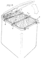
- 1 and 2 differently designed holders are designated, on each of which a plurality of bags 3 can be arranged.
- Holding rods 4 for bags 3 are provided both on the holder 1 and on the holder 2.
- holding plates can also be provided.
- 1, 2, and 9 and 10 the adjacent bags 3 with the mutually facing edges 5 for the bag openings 16 are detachably fastened to the holding bars 4 or to the holding plate.
- a holding rod 4 serves in each case for holding the edge 5 of only one sack 3.
- the holding rods 4 are arranged movably on the holder 1 or 2 in the two aforementioned embodiments.
- the holder 2 is designed as a column 6, a plurality of holding rods 4 or holding plates being pivotably mounted on the holder 2. It is also possible, according to an embodiment not shown, to fix the holding rods 4 to the column 6 in a predetermined position. This fixation can take place, for example, by means of a screw which is screwed through the bearing sleeve of the bars 4 in the area of the column 6 and is pressed with its end face against the column 6.
- the holding rods 4 are supported in the embodiment according to FIGS. 9 and 10 with their free ends on a support frame 7 which surrounds the column 6 at a radial distance.
- the support frame 7 can be designed as a U-profile, so that the free ends of the holding rods 4 rest on the flanges of the U-profile.
- the free ends of the holding rods 4 can also be provided with ball or needle bearings which engage in the U-profile.
- the holder 1 is designed as a square frame 8.
- the support rods 4 span the frame opening 9.
- the support frame 8 is formed at least on two mutually opposite spars of C-profiles, in which the support strips 4 engage with their ends.
- the ends of the holding strips 4 can be designed differently.
- a T-shaped end can be provided, according to FIG. 4 the end of the holding strips 4 is bent at an angle. 3 and 4, the support rods 4 can slide in the longitudinal direction of the frame bars.
- the ends of the holding rods 4 can also be provided with ball bearings or needle bearings so that the mobility of the holding rods in the longitudinal direction of the bars of the frame 8 is improved.
- the ends of the holding rod 4 are angled and engage in the space between the web and the upwardly angled flange end of the spar of the frame 8 which has a C-shaped cross section.
- the holding rod 4 can be prevented from sliding out of the frame 8 in this way.
- the support frame 7 or the Frame 8 may be provided in a manner not shown with notches, with which the holding rods 4 can be brought into engagement. These notches can be provided on the lower flange of the support frame 7 or on the lower flange of the frame 8.
- the holding rods 4 can be provided for the releasable attachment of the bags 3 with hooks 11, in which the bags, which are provided with holes, are hung.
- terminal strips or push buttons can also be provided in a manner not shown separately. In this case, bags without holes or handles can be used.
- FIGS. 6 and 7 show various possible arrangements of hooks 11 on the holding rods 5.
- the hooks 11 are arranged on riders 12. If the hooks 11 arranged on different sides of the holding rod 4 are to be aligned with one another, an embodiment according to FIG. 7 is recommended in which two hooks 11 are arranged opposite one another on a rider 12; However, if it is desired not to align the hooks 11, which are arranged on a holding rod 4 on different sides, with one another, an arrangement according to FIG. 6 can also be provided, in which a rider 12 has a hook 11 only on one side is provided. This embodiment is also used if only one sack 3 is attached to a movable holding rod 4, as shown in FIG. 14.
- the tabs 12 can be moved along the support rods 4 as desired.
- the upper side of the holding rods 4 can also be provided with notches with which the riders 12 can be brought into engagement, so that an unintentional displacement of the hooks 11 on the holding rods 4 is prevented.
- FIG. 8 A further possibility of arranging hooks 11 is shown in FIG. 8.
- the holding rod 4 consists of a double-T profile, the flanges of which are angled at the ends, so that plates 13 which carry the hooks 11 are in the free Space between the web and the angled flange ends inserted can be.
- the bends of the flanges can be provided at one point with openings through which the plates 13 can be inserted.
- Additional openings 17 in the region of the opening edge of the sack can be used to hang the sack into hooks 11 on the holding rod 4, which are also provided.
- the container 10 can be provided with a lid (only shown in FIG. 15) both in the round and in the square version, so that the sacks are then closed to the outside.
- the brackets designed as riders 12 for the releasable fastening of the opening edge of the bags 3 are slidably (slidably) arranged on the holding rods 4 and also on the cross member of the frame 8.
Description
Die Erfindung betrifft eine Halteeinrichtung für Säcke mit einem Halter, an dem mehrere Säcke angeordnet sind, wobei an dem Halter mindestens ein Haltestab lösbar und bewegbar angeordnet ist, der mit Halterungen zur lösbaren Befestigung eines Öffnungsrandes eines der Säcke oder einander zugekehrter Ränder der Öffnungen einander in der Halteeinrichtung benachbarter Säcke versehen ist, wobei der mindestens eine Haltestab mit beiden Enden an Holmen eines Rahmens, dessen Öffnung überspannend, gelagert ist. Säcke werden häufig dazu verwendet, Abfälle der verschiedensten Art aufzunehmen, um nach Füllung der Säcke abtransportiert zu werden. Handelt es sich dabei um Müll, so ist es wünschenswert, die Trennung des anfallenden Mülls möglichst bereits am Ort, an dem der Müll anfällt, vorzunehmen. Hiezu ist es erforderlich, daß der Müll je nach Gattung in getrennte Säcke aufgeteilt wird. Diese Säcke sollen leicht zugänglich sein, da erfahrungsgemäß nur dann eine Mülltrennung am Entstehungsort durchgeführt wird, wenn mit dieser Trennung kein besonderer Mehraufwand entsteht. Vor allem wird gefordert, daß die Säcke leicht aus der Haltevorrichtung entfernt und durch neue Säcke ersetzt werden können.The invention relates to a holding device for sacks with a holder on which a plurality of sacks are arranged, wherein at least one holding rod is detachably and movably arranged on the holder, which with holders for releasably fastening an opening edge of one of the sacks or mutually facing edges of the openings in each other the holding device of adjacent sacks is provided, the at least one holding rod being supported with both ends on spars of a frame, the opening of which spans. Sacks are often used to collect all kinds of waste in order to be transported away after the sacks have been filled. If it is garbage, it is desirable to separate the resulting garbage at the location where the garbage is generated. For this purpose, it is necessary that the garbage is divided into separate bags depending on the type. These sacks should be easily accessible, as experience has shown that waste is only separated at the point of origin if this separation does not result in any particular additional effort. Above all, it is required that the bags can be easily removed from the holding device and replaced with new bags.
Bekannt wurden Halteeinrichtungen für Säcke in Absackvorrichtungen, das sind Vorrichtungen, in welchen ein Sack an einem vorgegebenen Ort befüllt und mindestens ein weiterer Sack an einem benachbarten Ort in Bereitschaft gehalten wird, um in die Befüllungsstellung gebracht zu werden, nachdem der bereits befüllte Sack entfernt wurde (DE-A-15 86 264).Holding devices for sacks in bagging devices have become known, these are devices in which a bag is filled at a predetermined location and at least one further bag is held ready at an adjacent location in order to be brought into the filling position after the already filled bag has been removed (DE-A-15 86 264).
Unterschiedlich zu den vorerwähnten Absackvorrichtungen werden bei Einrichtungen zum Sammeln von getrenntem Müll in Säcken, mehrere Säcke zur gleichzeitigen Befüllung an voneinander verschiedenen Orten bereitgehalten.Damit ist das Einsatzgebiet der Absackvorrichtungen verschieden vom Einsatzgebiet von Müllsammeleinrichtungen, die Säcke für die verschiedensten Müllsorten verwenden, wiewohl in der konstruktiven Gestaltung durchaus gewisse Parallelitäten vorhanden sein können.Different from the above-mentioned bagging devices, devices for collecting separate rubbish in sacks have several sacks ready for simultaneous filling in different locations constructive design there may be certain parallelisms.
Für Absackeinrichtungen wurde aus der GB-A-1 317 995 eine Halteeinrichtung für Säcke mit einem Halter bekannt, an dem mehrere Säcke angeordnet sind, wobei an dem Halter mindestens ein Haltestab lösbar und bewegbar, z.B. gleitbar, gegebenenfalls an einer gewünschten Stelle des Halters z.B. mittels Kerben für den Eingriff der Haltestäbe festlegbar angeordnet ist, der mit Halterungen zur lösbaren Befestigung des Öffnungsrandes eines der Säcke oder der einander zugekehrten Ränder der Öffnungen einander in der Halteeinrichtung benachbarter Säcke versehen ist. Bei dieser Einrichtung ist ein gerader bzw. kreissektorförmig gekrümmter Holm zur Aufnahme der Haltestäbe bekanntgeworden. Die Haltestäbe stehen fliegend von diesem Holm ab, sodaß die gesamte Halteeinrichtung relativ instabil ist.For bagging devices from GB-A-1 317 995 a holding device for sacks with a holder on which several sacks are arranged has been known, at least one holding rod being releasable and movable on the holder, e.g. slidable, possibly at a desired location on the holder e.g. is arranged by means of notches for the engagement of the holding rods, which is provided with holders for releasably fastening the opening edge of one of the sacks or the mutually facing edges of the openings in the holding device of adjacent sacks. In this device, a straight or circular sector-shaped spar for receiving the holding rods has become known. The holding rods protrude from this spar so that the entire holding device is relatively unstable.
Bei Absackvorrichtungen ist schließlich auch bereits bekanntgeworden (vgl. etwa die DE-A-15 86 264), die Haltestäbe an einander gegenüberliegenden Holmen eines U-förmig ausgebildeten, somit auf einer Seite offenen Halters anzuordnen. Diese bekannten Einrichtungen sind zwar günstig, was den Abtransport der Säcke betrifft, hinsichtlich der gewünschten Stabilität, insbesondere wenn - wie im Falle von Müllsammeleinrichtungen - mehr als ein Sack zur gleichzeitigen Befüllung zur Verfügung gestellt werden soll, jedoch ungenügend. Die Belastung des U-förmigen Halters in der bekannten Absackvorrichtung ist dabei nur von kurzer Dauer, ebenfalls unterschiedlich zu Müllsammelvorrichtungen.In the case of bagging devices, it has finally also become known (cf., for example, DE-A-15 86 264) to arrange the holding rods on mutually opposite bars of a U-shaped holder which is thus open on one side. Although these known devices are inexpensive as far as the removal of the bags is concerned, they are insufficient in terms of the desired stability, in particular if - as in the case of garbage collection devices - more than one bag is to be made available for simultaneous filling. The load on the U-shaped holder in the known bagging device is only of short duration, also different from waste collection devices.
In der DE-A-12 07 259 ist weiters eine Absackvorrichtung beschrieben, bei der die Haltestäbe mit ihren freien Enden an einem geschlossenen Stützrahmen gehalten sind, der als kreisförmiger Laufschienenring ausgebildet ist. Die Sackklemmen sind dabei als von einer gemeinsamen Nabe radial abstehende Speichen ausgebildet, wodurch die Öffnungen der Säcke, deren Ränder zwischen zwei einander benachbarten Speichen geklemmt sind, jeweils konstant sind. Eine Anpassung der Sacköffnung an den jeweiligen Füllzustand des Sackes ist bei der Einrichtung gemäß der DE-A-12 07 259 nicht möglich.DE-A-12 07 259 also describes a bagging device in which the holding rods are held with their free ends on a closed support frame which is designed as a circular track ring. The bag clamps are designed as spokes projecting radially from a common hub, whereby the openings of the bags, the edges of which are clamped between two adjacent spokes, are each constant. An adaptation of the bag opening to the respective filling state of the bag is not possible with the device according to DE-A-12 07 259.
Die Erfindung bietet nun für das Problem, den anfallenden Müll bereits am Ort, an dem der Müll anfällt, zu trennen, eine Lösung, wobei der Müll je nach Gattung in getrennte Säcke aufgeteilt werden kann und die Säcke leicht zugänglich angeordnet und aus der Halteeinrichtung leicht entfernt und durch neue Säcke ersetzt werden können. Auf die Stabilität der Einrichtung ist dabei besonderes Augenmerk zu richten, bei der Müll unterschiedlichsten spez. Gewichts anfallt und demgemäß die von der Einrichtung aufzunehmende Last bei gleichem Volumen unterschiedlich sein kann. Die Erfindung geht hiebei aus von einer Halteeinrichtung für Säcke der eingangs erwähnten Art und schlägt zur Lösung der vorerwähnten Aufgabe vor, daß erfindungsgemäß die Holme für die Lagerung der Haltestäbe bzw. einer Halteplatte Teile eines geschlossenen vieleckigen, insbesondere viereckigen Rahmens bilden. Durch die erfindungsgemäße Gestaltung wird eine Halteeinrichtung erzielt, die es erlaubt, mehrere Säcke auf einfache Weise offenzuhalten, um unterschiedlichste Müllsorten (organischen Müll, Glas, Metall, Sondermüll usw.) in die hiefür vorgesehenen Säcke einzuwerfen und nach der Füllung der Säcke diese aus der Halteeinrichtung voneinander sowohl zeitlich als auch örtlich getrennt entfernen zu können und neue Säcke mit offenem Einwurfrand wieder in die Halteeinrichtung einzusetzen. Die einzelnen Säcke können unterschiedlich markiert (gefärbt) sein, um die einzelnen Müllsorten anhand der Markierung zu unterscheiden. In der Halteeinrichtung selbst können die Säcke an die jeweils gewünschte Stelle zur Erleichterung der Befüllung gebracht werden. Sind die Haltestäbe permanent beweglich, so paßt sich die Sacköffnung der jeweiligen Befüllung an. Die erfindungsgemäße Vorrichtung erreicht dadurch, daß der mindestens eine Haltestab bzw. eine Halteplatte mit beiden Enden an Holmen eines geschlossenen, bevorzugt viereckigen Rahmens gelagert ist, die für die gleichzeitige Befüllung mehrerer Säcke erforderliche Stabilität in ausreichendem Maße. Die erfindungsgemäße Halteeinrichtung eignet sich daher besonders für einen Einsatz, bei welchem mehrere Säcke zur Verfügung stehen, um unterschiedliches Gut, etwa verschiedenartigen Müll, aufzunehmen. Von besonderem Interesse kann es dabei sein, die Halterungen zur lösbaren Befestigung des Öffnungsrandes der Säcke verstellbar und feststellbar am jeweiligen Haltestab anzuordnen. Auf diese Weise gelingt es nämlich, verschiedene Sacktypen an der gleichen Halteeinrichtung einzusetzen, insbesondere können als Säcke zur Aufnahme von Müll auch übliche Tragtaschen eingesetzt werden, womit diese Tragtaschen vor ihrer Vernichtung noch einem Zweck zugeführt werden können. Auch bereits vorhandene Behälter können mit erfindungsgemäßen Halteeinrichtungen ausgestattet werden, nämlich dann, wenn der Rahmen für die Haltestäbe vom Öffnungsrand des Behälters gebildet ist oder der Rahmen auf den Öffnungsrand des Behälters aufgesetzt werden kann.The invention now offers a solution to the problem of separating the resulting garbage at the location where the garbage occurs, the garbage can be divided into separate bags depending on the genre and the sacks arranged in an easily accessible manner and can be easily removed from the holding device and replaced with new bags. Particular attention should be paid to the stability of the facility, in the case of various types of waste. Weight accrues and accordingly the load to be absorbed by the device can be different for the same volume. The invention is based on a holding device for bags of the type mentioned at the outset and proposes to solve the above-mentioned object that, according to the invention, the spars for the storage of the holding rods or a holding plate form parts of a closed polygonal, in particular square frame. With the design according to the invention, a holding device is achieved which allows several sacks to be kept open in a simple manner in order to throw different types of waste (organic waste, glass, metal, special waste etc.) into the sacks provided for this purpose and after the sacks have been filled, they are removed from the To be able to remove the holding device separately from one another both in terms of time and location and to reinsert new bags with the throw-in edge open into the holding device. The individual bags can be marked (colored) differently in order to distinguish the individual types of waste based on the marking. In the holding device itself, the bags can be brought to the desired location in order to facilitate filling. If the holding rods are permanently movable, the bag opening adapts to the respective filling. The device according to the invention achieves the fact that the at least one holding rod or holding plate with both ends is mounted on spars of a closed, preferably square frame, the stability required for the simultaneous filling of several bags to a sufficient extent. The holding device according to the invention is therefore particularly suitable for an application in which a plurality of sacks are available to accommodate different goods, such as different types of waste. It can be of particular interest to arrange the holders for the releasable fastening of the opening edge of the sacks in an adjustable and lockable manner on the respective holding rod. In this way it is possible to use different types of sacks to be used on the same holding device, in particular conventional carrying bags can also be used as sacks for holding garbage, so that these carrying bags can be used for a purpose before they are destroyed. Even existing containers can be equipped with holding devices according to the invention, namely when the frame for the holding rods is formed by the opening edge of the container or the frame can be placed on the opening edge of the container.
Die der Erfindung zugrundeliegende Idee laßt sich auch mit rundem Stützrahmen verwirklichen. Die Erfindung geht dabei aus von einer Halteeinrichtung für Säcke mit einem Halter, der als Säule ausgebildet ist, an der mehrere Haltestäbe bzw. Halteplatten schwenkbar gelagert sind, wobei der Haltestab bzw. die Halteplatte mit Halterungen zur lösbaren Befestigung des Öffnungsrandes eines der Säcke bzw. der einander zugekehrten Ränder der Öffnungen einander in der Halteeinrichtung benachbarter Säcke versehen ist, wobei die Haltestäbe bzw. die Halteplatten mit ihren freien Enden an einem Stützrahmen gehalten sind, der die Säule mit radialem Abstand umschließt, wobei bei einer solchen Einrichtung erfindungsgemäß die Haltestäbe bzw. Halteplatten aufeinander zu und voneinander wegschwenkbar an der Säule gelagert sind und gegebenenfalls, z.B. mittels am Stützrahmen angeordneter Kerben, in welche die Haltestäbe bzw. Halteplatten eingreifen, festlegbar sind. Diese Gestaltung ermöglicht eine Anpassung der Sacköffnung an den jeweiligen Füllzustand des Sakkes. Die Haltestäbe sind hiebei aufeinander zu- und voneinander wegschwenkbar auf der Säule gelagert. Soferne jedoch mittels am Stützrahmen angeordneter Kerben die Haltestäbe festgelegt werden können, ist es möglich, an der Halteeinrichtung Säcke anzuordnen, deren Öffnungen verschieden groß sind. Auch bei dieser Ausführungsform ist es möglich, daß der Stützrahmen für die von der Säule abliegenden Enden der Haltestäbe vom Öffnungsrand eines Behälters gebildet ist oder der Stützrahmen auf den Öffnungsrand des Behälters aufgesetzt wird. Dadurch ist es möglich, vorhandene etwa kreisförmige Tonnen, mit erfindungsgemäß ausgestalteten Halteeinrichtungen für Säcke zu versehen und damit unterschiedlichen Müll oder anderen Abfall bereits am Entstehungsort zu sortieren.The idea on which the invention is based can also be realized with a round support frame. The invention is based on a holding device for sacks with a holder which is designed as a column on which a plurality of holding rods or holding plates are pivotably mounted, the holding rod or holding plate with holders for releasably fastening the opening edge of one of the sacks or of the mutually facing edges of the openings in the holding device of adjacent sacks is provided, the holding rods or the holding plates being held with their free ends on a support frame which surrounds the column at a radial distance, the holding rods or Retaining plates are mounted on the column so that they can be swiveled towards and away from one another and, if necessary, can be fixed, for example by means of notches arranged on the support frame, into which the holding rods or holding plates engage. This design enables the bag opening to be adapted to the respective filling status of the jacket. The holding rods are mounted on the column so that they can be swiveled towards and away from one another. However, if the holding rods can be fixed by means of notches arranged on the support frame, it is possible to arrange sacks on the holding device, the openings of which are of different sizes. In this embodiment too, it is possible for the support frame for the ends of the holding rods remote from the column to be formed by the opening edge of a container or for the support frame to be placed on the opening edge of the container. This makes it possible to provide existing approximately circular bins with holding devices for sacks designed in accordance with the invention and thus to sort different garbage or other waste at the point of origin.
Die Halterungen zur lösbaren Befestigung des Öffnungsrandes einer der Säcke können verstellbar und feststellbar am jeweiligen Haltestab angeordnet sein; dies mit dem Ziele, unterschiedliche Säcke, etwa auch Tragtaschen, in der erfindungsgemäßen Halteeinrichtung verwenden zu können.The brackets for releasably fastening the opening edge of one of the sacks can be arranged on the respective holding rod in an adjustable and lockable manner; this with the aim of being able to use different sacks, for example also carrier bags, in the holding device according to the invention.
Auch mit nur einem einzigen Haltestab können in der Halteeinrichtung zwei Säcke untergebracht werden, wobei jeweils ein Öffnungsrand eines Sackes am Rahmen und an dem beweglichen, gegebenenfalls arretierbaren Haltestab gehalten ist.Even with just a single holding rod, two sacks can be accommodated in the holding device, an opening edge of a sack being held on the frame and on the movable, possibly lockable holding rod.
Der Stützrahmen bzw. der Rahmen für die Ausführung, bei der der Halter als Säule ausgebildet ist, kann vom Öffnungsrand eines Behälters gebildet sein, jedoch ist es auch möglich, den Stützrahmen bzw. den Halterahmen für die Haltestäbe auf die Öffnung des Behälters aufzusetzen oder in diese einzusetzen. Der Stützrahmen bzw. der Rahmen für die Aufnahme der Haltestäbe kann auch von Füßen getragen werden, die am Boden abgestützt sind, oder es kann der Stützrahmen bzw. der Rahmen für die Aufnahme der Haltestäbe auch nach Art einer Konsole an einer Mauer, Wand oder der Innenseite einer Kastentür befestigt werden.The support frame or the frame for the embodiment in which the holder is designed as a column can be formed by the opening edge of a container, but it is also possible to place the support frame or the holding frame for the holding rods on the opening of the container or in to use them. The support frame or the frame for receiving the support rods can also be carried by feet that are supported on the floor, or it can be the support frame or the frame for receiving the support rods in the manner of a console on a wall, wall or the Be fastened inside a box door.
Sind die Haltestäbe mit ihren freien Enden gleitbar in bzw. an dem Stützrahmen bzw. an dem viereckigen Rahmen für die Aufnahme der Haltestäbe gelagert, so können an den Stabenden auch Kugellager oder Nagellager vorgesehen sein, über welche die Haltestäbe an dem Stützrahmen bzw. an dem Rahmen für die Haltestäbe gelagert sind.If the holding rods are slidably mounted with their free ends in or on the support frame or on the square frame for receiving the holding rods, ball bearings or nail bearings can also be provided on the rod ends, via which the holding rods on the support frame or on the Framework for the support rods are stored.
Zur lösbaren Befestigung der Säcke können die Haltestäbe mit Klemmleisten oder mit Haken, Druckknöpfen u.dgl. versehen sein, die bevorzugt ver- und feststellbar am jeweiligen Haltestab angeordnet sind. Sind diese Halteeinrichtungen für die Säcke verstellbar am jeweiligen Haltestab angeordnet, ist es möglich, Säcke zu verwenden, an welchen Einhängeösen in unterschiedlicher gegenseitiger Entfernung vorgesehen sind. Die verstellbare Anordnung der Haltemittel für die Säcke erlaubt es auch, herkömmliche Tragtaschen als Säcke zu verwenden und mit ihren Tragbügeln in die Halteelemente an den Haltestäben einzuhängen.For detachable attachment of the bags, the holding rods can be with clamp strips or with hooks, push buttons, etc. be provided, which are preferably arranged and lockable on the respective holding rod. If these holding devices for the sacks are adjustably arranged on the respective holding rod, it is possible to use sacks on which hanging eyes are provided at different mutual distances. The adjustable arrangement of the holding means for the sacks also makes it possible to use conventional carrier bags as sacks and to hang them on the holding elements on the holding rods with their carrying brackets.
Die Erfindung wird nachstehend anhand von in der Zeichnung dargestellten Ausführungsbeispielen näher und beispielsweise erläutert. Es zeigen,
- Fig. 1 eine Draufsicht auf eine erfindungsgemäß ausgestaltete Halteeinrichtung,
- Fig. 2 einen Schnitt entlang der Linie II-II in Fig. 1,
- Fig. 3 einen Teilschnitt entlang der Linie III-III in Fig. 1, die
- Fig. 4 und 5 gegenüber der Ausführungsform der Fig. 3 abgeänderte Lagerungen von Haltestäben, die
- Fig. 6 einen Schnitt nach der Linie VI-VI in Fig. 1, die
- Fig. 7 und 8 unterschiedliche Ausführungsformen von Haltestäben und Halteeinrichtungen für Säcke,
- Fig. 9 in Draufsicht eine weitere Ausführungsform einer erfindungsgemäßen Halteeinrichtung,
- Fig. 1O einen Schnitt entlang der Linie X-X in Fig. 9,
- Fig. 11 eine Ausführungsform eines in der erfindungsgemäßen Halteeinrichtung verwendbaren Sackes,
- Fig. 12 eine gegenüber Fig. 11 abgeänderte Sackform,
- Fig. 13 eine weitere Variante zu den Ausführungen der Fig. 6 bis 8,
- Fig. 14 eine Ausführungsform, die gegenüber jener in Fig. 2 modifiziert ist, und
- Fig. 15 eine weitere Ausführungsform, bei der große und kleine Säcke in der Halteeinrichtung angeordnet sind und der Halter vom Öffnungsrand eines Containers gebildet ist.
- 1 is a plan view of a holding device designed according to the invention,
- 2 shows a section along the line II-II in FIG. 1,
- Fig. 3 is a partial section along the line III-III in Fig. 1, the
- 4 and 5 compared to the embodiment of FIG. 3 modified bearings of holding rods, the
- Fig. 6 is a section along the line VI-VI in Fig. 1, the
- 7 and 8 different embodiments of holding rods and holding devices for sacks,
- 9 is a plan view of a further embodiment of a holding device according to the invention,
- 1O is a section along the line XX in Fig. 9,
- 11 shows an embodiment of a sack which can be used in the holding device according to the invention,
- 12 is a modified bag shape compared to FIG. 11,
- 13 shows a further variant of the embodiments of FIGS. 6 to 8,
- Fig. 14 shows an embodiment modified from that in Fig. 2, and
- 15 shows a further embodiment in which large and small sacks are arranged in the holding device and the holder is formed by the opening edge of a container.
In der Zeichnung sind mit 1 und 2 unterschiedlich ausgebildete Halter bezeichnet, an welchen jeweils mehrere Säcke 3 angeordnet werden können. Sowohl an dem Halter 1 als auch an dem Halter 2 sind Haltestäbe 4 für Säcke 3 vorgesehen. Statt Haltestäben 4 können auch Halteplatten vorgesehen werden. An den Haltestäben 4 bzw. an der Halteplatte sind gemäß den Fig. 1, 2 sowie 9 und 10 die benachbarten Säcke 3 mit den einander zugekehrten Rändern 5 für die Sacköffnungen 16 lösbar befestigt. In der Ausführungsform gemäß Fig. 13 hingegen dient ein Haltestab 4 jeweils zur Halterung des Randes 5 nur eines Sackes 3. Die Haltestäbe 4 sind in beiden vorgenannten Ausführungsformen beweglich am Halter 1 bzw. 2 angeordnet.In the drawing, 1 and 2 differently designed holders are designated, on each of which a plurality of
In der Ausführungsform nach den Fig. 9 und 10 ist der Halter 2 als Säule 6 ausgebildet, wobei mehrere Haltestäbe 4 bzw. Halteplatten schwenkbar an dem Halter 2 gelagert sind. Es ist auch möglich, gemäß einer nicht dargestellten Ausführungsform die Haltestäbe 4 an der Säule 6 in einer vorgegebenen Stellung zu fixieren. Diese Fixierung kann beispielsweise durch eine Schraube erfolgen, welche durch die Lagerhülse der Stäbe 4 im Bereich der Säule 6 geschraubt und mit ihrer Stirnfläche gegen die Säule 6 gepreßt wird. Die Haltestäbe 4 sind in der Ausführungsform gemaß den Fig. 9 und 10 mit ihren freien Enden an einem Stützrahmen 7 abgestützt, der die Säule 6 mit radialem Abstand umschließt. Der Stützrahmen 7 kann dabei als U-Profil ausgebildet sein, sodaß die freien Enden der Haltestäbe 4 an den Flanschen des U-Profiles anliegen. Die freien Enden der Haltestäbe 4 können dabei auch mit Kugel- oder Nadellagern versehen sein, die in das U-Profil eingreifen.In the embodiment according to FIGS. 9 and 10, the
In der Ausführungsform nach den Fig. 1 und 2 sowie 14 ist der Halter 1 als viereckiger Rahmen 8 ausgebildet. Die Haltestäbe 4 überspannen dabei die Rahmenöffnung 9. Der Stützrahmen 8 wird zumindest an zwei einander gegenüberliegenden Holmen von C-Profilen gebildet, in welche die Halteleisten 4 mit ihren Enden eingreifen. Die Enden der Halteleisten 4 können dabei unterschiedlich ausgebildet sein.In the embodiment according to FIGS. 1 and 2 and 14, the holder 1 is designed as a
Gemäß Fig. 3 kann etwa ein T-förmiges Ende vorgesehen sein, gemäß Fig. 4 ist das Ende der Halteleisten 4 winkelförmig abgekröpft. Gemäß den Fig. 3 und 4 können die Haltestäbe 4 in Längsrichtung der Rahmenholme gleiten. Die Enden der Haltestäbe 4 können auch mit Kugellagern oder Nadellagern versehen sodaß die Bewegbarkeit der Haltestäbe in Längsrichtung der Holme des Rahmens 8 verbessert ist.According to FIG. 3, a T-shaped end can be provided, according to FIG. 4 the end of the holding strips 4 is bent at an angle. 3 and 4, the
In der Ausführungsform gemäß Fig. 13 sind die Enden des Haltestabes 4 abgewinkelt und greifen in den Raum zwischen dem Steg und dem nach oben abgewinkelten Flanschende des C-förmigen Querschnitt aufweisenden Holm des Rahmens 8 ein. Bei Schrägstellung des Haltestabes gegenüber dem Rahmenholm kann solcherart ein Herausgleiten des Haltestabes 4 aus dem Rahmen 8 verhindert werden.In the embodiment according to FIG. 13, the ends of the holding
Um in einfacher Weise die Haltestäbe 4 in einer jeweils gewünschten Stellung am Stützrahmen 7 bzw. am Rahmen 8 zu halten, kann der Stützrahmen 7 bzw. der Rahmen 8 in nicht gesondert dargestellter Weise mit Kerben versehen sein, mit welchen die Haltestäbe 4 in Eingriff gebracht werden können. Diese Kerben können dabei am unteren Flansch des Stützrahmens 7 bzw. am unteren Flansch des Rahmens 8 vorgesehen werden.In order to hold the holding
Der Stützrahmen 7 und auch der Rahmen 8 in der eckigen Ausführung gemäß Fig. 1 kann vom Öffnungsrand eines Behälters 10 gebildet sein, es ist jedoch auch möglich, den Stützrahmen 7 bzw. den Rahmen 8 auf den Öffnungsrand des Behälters 10 aufzusetzen oder in die Öffnung einzusetzen. Die Haltestäbe 4 können zur lösbaren Befestigung der Säcke 3 mit Haken 11 versehen sein, in welche die Säcke, die mit Löchern versehen sind, eingehängt werden. Zum Halten der Säcke können auch Klemmleisten oder Druckknöpfe in nicht gesondert dargestellter Weise vorgesehen sein. In diesem Fall können Säcke ohne Löcher oder Handgriffe verwendet werden.1 can be formed by the opening edge of a
Die Fig. 6 bis 8 zeigen verschiedene mögliche Anordnungen von Haken 11 an den Haltestäben 5. In der Ausführungsform nach den Fig. 6 und 7 sind die Haken 11 an Reitern 12 angeordnet. Soferne die an unterschiedlichen Seiten des Haltestabes 4 angeordneten Haken 11 miteinander fluchten sollen, empfiehlt sich eine Ausführung gemäß Fig. 7, bei der an einem Reiter 12 zwei Haken 11 einander gegenüberliegend angeordnet sind; ist es jedoch gewünscht, die Haken 11, die an einem Haltestab 4 auf unterschiedlichen Seiten angeordnet sind, nicht miteinander fluchtend anzuordnen, so kann auch eine Anordnung gemäß Fig. 6 vorgesehen werden, bei der ein Reiter 12 nur an einer Seite mit einem Haken 11 versehen ist. Diese Ausführungsform findet auch Verwendung, wenn nur ein Sack 3 an einem beweglichen Haltestab 4 befestigt wird, wie dies Fig. 14 zeigt. Die Reiter 12 können beliebig entlang der Haltestäbe 4 verschoben werden. Die Oberseite der Haltestäbe 4 kann auch mit Kerben versehen sein, mit welchen die Reiter 12 in Eingriff gebracht werden können, sodaß ein unbeabsichtigtes Versetzen der Haken 11 an den Haltestäben 4 verhindert ist.6 to 8 show various possible arrangements of
Eine weitere Möglichkeit der Anordnung von Haken 11 zeigt die Fig. 8. In dieser Ausführungsform besteht der Haltestab 4 aus einem Doppel-T-Profil, dessen Flanschen an den Enden abgewinkelt sind, sodaß Plättchen 13, welche die Haken 11 tragen, in den freien Raum zwischen dem Steg und den abgewinkelten Flanschenden eingesetzt werden können. Die Abwinkelungen der Flanschen können dabei an einer Stelle mit Durchbrechungen versehen sein, durch welche die Plättchen 13 hindurchgesteckt werden können.A further possibility of arranging
In den Fig. 11 und 12 sind zwei Ausführungsformen von Säcken 3 gezeichnet. Gemäß Fig. 11 besitzt der Sack 3 unterhalb seines Öffnungsrandes zwei Ausnehmungen 17. Mit diesen Ausnehmungen 17 kann der Sack 3 in die Haken 11 eingehängt werden. In der Ausführungsform nach Fig. 12 ist im Bereich der Öffnung des Sackes 3 ein Griff 15 in der Mitte vorgesehen, der entweder in einen oder auch in zwei ihm benachbarte Haken 11 eingehängt werden kann.11 and 12, two embodiments of
Zusätzliche Öffnungen 17 im Bereich des Öffnungsrandes des Sackes können dazu verwendet werden, den Sack in weiters vorgesehene Haken 11 am Haltestab 4 einzuhängen.
Der Behälter 10 kann sowohl in der runden als auch in der eckigen Ausführung mit einem Deckel (nur in Fig. 15 dargestellt) versehen werden, sodaß dann die Säcke nach außen verschlossen sind.The
In der Ausführungsform gemäß Fig. 15 sind die als Reiter 12 ausgebildeten Halterungen zur lösbaren Befestigung des Öffnungsrandes der Säcke 3 verschiebbar (gleitbar) an den Haltestäben 4 und auch am Querholm des Rahmens 8 angeordnet. Damit können auch mehrere kleine Säcke zwischen zwei einander benachbarten Haltestäben 4 bzw. wie in Fig. 15 dargestellt, im Raum zwischen einem Querholm des Rahmens 8 und dem diesem Querholm benachbarten Haltestab 4 angeordnet werden. Es ist auch möglich, die Reiter in einer jeweils gewünschten Lage am Haltestab 4 bzw. am Holm des Rahmens 8 festzustellen.In the embodiment according to FIG. 15, the brackets designed as
Claims (7)
- Support device for bags (3) with a support (1) on which a plurality of bags (3) are arranged, whereby releasably and movably arranged on the support (1) there is at least one support bar (4), which is provided with holders for releasably securing the opening edge (5) of one of the bags (3) or the edges (5) directed towards one another of the openings (16) of bags (3) adjacent to one another in the support device, whereby the at least one support bar (4) is mounted with both ends on beams of a frame (8), extending across the opening (9) thereof, characterised in that the beams for the mounting of the support bar or a support plate constitute portions of a closed, polygonal, particularly quadrangular, frame (8).
- Support device as claimed in Claim 1, characterised in that the frame (8) for the support bars (4) or support plates is constituted by the opening edge of a container (10) or is placed on the opening edge of the container (10).
- Support device as claimed in Claim 1 or 2, characterised in that the holders for releasably securing the opening edge of the bags (3) are arranged in a manner known per se so as to be movable and adjustable on the respective support bar (4) or on the respective support plate and preferably on a beam of the frame (8) adjacent to a support bar (4).
- Support device as claimed in one of Claims 1 to 3, characterised in that the support bar (4) is fixable in a manner known per se to a desired position on the support, e.g. by means of depressions for the engagement of the support bars.
- Support device for bags with a support (2) which is constructed as a column (6) on which a plurality of support bars (4) or support plates are pivotably mounted, whereby the support bar (4) or the support plate is provided with holders for releasably securing the opening edge (5) of one of the bags (3) or the edges (5) directed towards one another of the opening (16) of bags adjacent to one another in the support device, whereby the support bars (4) or the support plates are supported with their free ends on a support frame (7), which surrounds the column (6) at a radial spacing, characterised in that the support bars (4) or support plates are mounted on the column (6) so as to be pivotable towards one another and away from one another and are optionally fixable, e.g. by means of depressions arranged on the support frame (7) in which the support bars (4) or support plates engage.
- Support device as claimed in Claim 5, characterised in that the support frame (7) for the ends of the support bars (4) or support plates spaced away from the column (6) is constituted by the opening edge of a container or the support frame (7) is placed on the opening edge of the container (10).
- Support device as claimed in Claim 5 or 6, characterised in that the holders for releasably securing the opening edge of one of the bags are arranged so as to be movable and optionally fixable on the respective support bar (4).
Applications Claiming Priority (2)
| Application Number | Priority Date | Filing Date | Title |
|---|---|---|---|
| AT0076690A AT394540B (en) | 1990-04-03 | 1990-04-03 | HOLDING DEVICE FOR BAGS |
| AT766/90 | 1990-04-03 |
Publications (2)
| Publication Number | Publication Date |
|---|---|
| EP0451135A1 EP0451135A1 (en) | 1991-10-09 |
| EP0451135B1 true EP0451135B1 (en) | 1994-09-21 |
Family
ID=3499204
Family Applications (1)
| Application Number | Title | Priority Date | Filing Date |
|---|---|---|---|
| EP91890067A Expired - Lifetime EP0451135B1 (en) | 1990-04-03 | 1991-04-03 | Supporting device for bags |
Country Status (4)
| Country | Link |
|---|---|
| US (1) | US5380081A (en) |
| EP (1) | EP0451135B1 (en) |
| AT (1) | AT394540B (en) |
| DE (1) | DE59102989D1 (en) |
Families Citing this family (22)
| Publication number | Priority date | Publication date | Assignee | Title |
|---|---|---|---|---|
| DE29515727U1 (en) * | 1995-10-05 | 1996-01-25 | Fietz Erwin H Gmbh | Device for collecting textiles with several collecting containers |
| US5639050A (en) * | 1996-04-05 | 1997-06-17 | Peterson; Wilma | Food storage bag holder |
| DE19615349A1 (en) * | 1996-04-18 | 1997-10-23 | Diebold Helmut Gmbh & Co | Clamping device for sack-type receiving container |
| FR2748453B1 (en) * | 1996-05-09 | 1998-07-10 | Rabaud Francois | DEVICE FOR THE SELECTIVE SORTING OF WASTE |
| US5735495A (en) * | 1996-06-05 | 1998-04-07 | Kubota; Teresita | Trash bag holding device |
| DE19713297A1 (en) * | 1997-03-29 | 1998-10-01 | Container Service Groeger Gmbh | Frame structure to hold sacks open |
| WO1999025616A1 (en) * | 1997-11-13 | 1999-05-27 | Cazeaux Jean Marie | Device for selective sorting of household refuse |
| USD404861S (en) * | 1998-01-09 | 1999-01-26 | Seymour Housewares Corporation | Laundry sorter |
| DE10005363C2 (en) * | 2000-02-07 | 2002-10-10 | Klean Contor Gmbh | Bag-like container for the disposal of waste materials |
| US6488243B2 (en) * | 2001-04-06 | 2002-12-03 | Seong Tae Kim | Bag holder for hanging on rims of miscellaneous items |
| US6508443B1 (en) | 2002-03-08 | 2003-01-21 | Mark J. Andreasson | Re-sealable food storage bag filling device |
| JP2008504118A (en) * | 2004-06-23 | 2008-02-14 | リーブテック,インコーポレイテッド | Mixing container alignment system, device and methods related thereto |
| US7210659B2 (en) * | 2005-01-11 | 2007-05-01 | Stephen Lawson | Combination of telescopically extendable frame with a laundry bag assembly |
| US20060157358A1 (en) * | 2005-01-14 | 2006-07-20 | Heidel Lena L | Clothes hamper assembly |
| US20070210546A1 (en) * | 2006-03-06 | 2007-09-13 | Rubbermaid Commercial Products Llc | Wheeled waste collection container |
| US7624915B2 (en) * | 2008-02-04 | 2009-12-01 | Riverwest Engineering & Design, Inc. | Recycling center |
| ITRM20110133A1 (en) * | 2011-03-21 | 2012-09-22 | David Marianecci | ELEMENT WITH BAGS FOR THE DIFFERENTIATED WASTE COLLECTION THAT INCLUDES A BARRIER OF SUPPORT AND ATTACHMENT |
| US8910813B1 (en) * | 2013-09-25 | 2014-12-16 | Neatfreak Group Inc. | Laundry hampers and sorters with accessible front loading regions |
| WO2019186745A1 (en) * | 2018-03-28 | 2019-10-03 | 武秀 山田 | Garbage box |
| CN110615200A (en) * | 2019-09-19 | 2019-12-27 | 芜湖职业技术学院 | Classification garbage can |
| CN111470207A (en) * | 2020-04-30 | 2020-07-31 | 粟陶美 | Space-saving household comprehensive household classification dustbin |
| US11851231B2 (en) * | 2021-02-04 | 2023-12-26 | Orbis Corporation | Bag hook for a hinged tote |
Family Cites Families (8)
| Publication number | Priority date | Publication date | Assignee | Title |
|---|---|---|---|---|
| US2625973A (en) * | 1951-08-31 | 1953-01-20 | John J Weldon | Laundry hamper |
| US2995329A (en) * | 1960-09-02 | 1961-08-08 | Jr Louie R Talcott | Sack holder |
| DE1207259B (en) * | 1963-04-26 | 1965-12-16 | Eugen Popp | Bagging device with bag hanging conveyor |
| FR1512638A (en) * | 1967-02-09 | 1968-02-09 | Bag suspension device | |
| DE1586264A1 (en) * | 1967-02-28 | 1970-07-23 | Smedlund Egon Gunnar | Holding device for bags |
| GB1317995A (en) * | 1971-05-10 | 1973-05-23 | Crisplant As | Suspension means for bags or sacks |
| IT1151650B (en) * | 1982-06-11 | 1986-12-24 | Francesco Canziani | DEVICE FOR THE QUICK CHANGE OF COLLECTION BAGS |
| US4979705A (en) * | 1989-03-27 | 1990-12-25 | Ralph Bovitz | Laundry bags and frame apparatus |
-
1990
- 1990-04-03 AT AT0076690A patent/AT394540B/en not_active IP Right Cessation
-
1991
- 1991-04-03 EP EP91890067A patent/EP0451135B1/en not_active Expired - Lifetime
- 1991-04-03 DE DE59102989T patent/DE59102989D1/en not_active Expired - Fee Related
-
1994
- 1994-01-24 US US08/186,311 patent/US5380081A/en not_active Expired - Fee Related
Also Published As
| Publication number | Publication date |
|---|---|
| AT394540B (en) | 1992-04-27 |
| EP0451135A1 (en) | 1991-10-09 |
| ATA76690A (en) | 1991-10-15 |
| US5380081A (en) | 1995-01-10 |
| DE59102989D1 (en) | 1994-10-27 |
Similar Documents
| Publication | Publication Date | Title |
|---|---|---|
| EP0451135B1 (en) | Supporting device for bags | |
| DE4422772A1 (en) | Crate holding device for baggage rack of bicycle | |
| DE1941854C3 (en) | Rack for storing bar material | |
| EP0894064A1 (en) | Transport device | |
| DE8331310U1 (en) | Basket especially for exhibition purposes and the like | |
| DE4236306A1 (en) | Holder for plastics refuse sacks - has holding ring with open profile to take elastic band. | |
| DE3534177C2 (en) | ||
| DE2748380C2 (en) | Bundle harness for material transport in mining and tunneling | |
| DE833321C (en) | Equipment for storage and transport of electricity meters | |
| DE19622508C1 (en) | Holder for solid roof, especially vehicle hard-top, on mobile frame | |
| DE3641132C2 (en) | Shelf for storing plate-shaped bodies | |
| DE8421274U1 (en) | LAUNDRY HOLDER OD. DGL. | |
| DE2424797C2 (en) | Holding device for suspension files | |
| DE8034462U1 (en) | HANGER | |
| DE3413300A1 (en) | Stacking apparatus for periodicals, newspapers and the like | |
| DE2714172A1 (en) | Display holder for decorative or adhesive foil supply rolls - has support strip and arms fitted into existing storage shelves | |
| DE828404C (en) | File holder | |
| DE3009745C2 (en) | Device for the detachable fastening of gripper heads on packaging machines | |
| CH310381A (en) | Equipment for storing and transporting objects. | |
| DE2424797B1 (en) | Suspension filing system - providing filing storage for suspended folders fitted with varying means of suspension | |
| DE8411356U1 (en) | Device for securing the position of transported goods in the trunk | |
| DE1076726B (en) | Loading equipment for transport vehicles | |
| DE8507886U1 (en) | Device for transporting boilers | |
| DE3728965A1 (en) | Container-like device for transporting and/or storing articles | |
| DE8131669U1 (en) | "Holding device for high jump crossbars" |
Legal Events
| Date | Code | Title | Description |
|---|---|---|---|
| PUAI | Public reference made under article 153(3) epc to a published international application that has entered the european phase |
Free format text: ORIGINAL CODE: 0009012 |
|
| AK | Designated contracting states |
Kind code of ref document: A1 Designated state(s): BE CH DE DK FR GB IT LI NL SE |
|
| 17P | Request for examination filed |
Effective date: 19920317 |
|
| 17Q | First examination report despatched |
Effective date: 19930201 |
|
| GRAA | (expected) grant |
Free format text: ORIGINAL CODE: 0009210 |
|
| AK | Designated contracting states |
Kind code of ref document: B1 Designated state(s): BE CH DE DK FR GB IT LI NL SE |
|
| PG25 | Lapsed in a contracting state [announced via postgrant information from national office to epo] |
Ref country code: IT Free format text: LAPSE BECAUSE OF FAILURE TO SUBMIT A TRANSLATION OF THE DESCRIPTION OR TO PAY THE FEE WITHIN THE PRE;WARNING: LAPSES OF ITALIAN PATENTS WITH EFFECTIVE DATE BEFORE 2007 MAY HAVE OCCURRED AT ANY TIME BEFORE 2007. THE CORRECT EFFECTIVE DATE MAY BE DIFFERENT FROM THE ONE RECORDED.SCRIBED TIME-LIMIT Effective date: 19940921 Ref country code: GB Effective date: 19940921 Ref country code: FR Effective date: 19940921 Ref country code: BE Effective date: 19940921 Ref country code: DK Effective date: 19940921 Ref country code: NL Effective date: 19940921 |
|
| REF | Corresponds to: |
Ref document number: 59102989 Country of ref document: DE Date of ref document: 19941027 |
|
| PG25 | Lapsed in a contracting state [announced via postgrant information from national office to epo] |
Ref country code: SE Effective date: 19941221 |
|
| EN | Fr: translation not filed | ||
| NLV1 | Nl: lapsed or annulled due to failure to fulfill the requirements of art. 29p and 29m of the patents act | ||
| GBV | Gb: ep patent (uk) treated as always having been void in accordance with gb section 77(7)/1977 [no translation filed] |
Effective date: 19940921 |
|
| PLBE | No opposition filed within time limit |
Free format text: ORIGINAL CODE: 0009261 |
|
| STAA | Information on the status of an ep patent application or granted ep patent |
Free format text: STATUS: NO OPPOSITION FILED WITHIN TIME LIMIT |
|
| PGFP | Annual fee paid to national office [announced via postgrant information from national office to epo] |
Ref country code: CH Payment date: 19950724 Year of fee payment: 5 |
|
| 26N | No opposition filed | ||
| PG25 | Lapsed in a contracting state [announced via postgrant information from national office to epo] |
Ref country code: LI Effective date: 19960430 Ref country code: CH Effective date: 19960430 |
|
| REG | Reference to a national code |
Ref country code: CH Ref legal event code: PL |
|
| PGFP | Annual fee paid to national office [announced via postgrant information from national office to epo] |
Ref country code: DE Payment date: 19990331 Year of fee payment: 9 |
|
| PG25 | Lapsed in a contracting state [announced via postgrant information from national office to epo] |
Ref country code: DE Free format text: LAPSE BECAUSE OF NON-PAYMENT OF DUE FEES Effective date: 20010201 |