EP0451125B1 - A feeding device for vegetable cutting machines - Google Patents
A feeding device for vegetable cutting machines Download PDFInfo
- Publication number
- EP0451125B1 EP0451125B1 EP91850078A EP91850078A EP0451125B1 EP 0451125 B1 EP0451125 B1 EP 0451125B1 EP 91850078 A EP91850078 A EP 91850078A EP 91850078 A EP91850078 A EP 91850078A EP 0451125 B1 EP0451125 B1 EP 0451125B1
- Authority
- EP
- European Patent Office
- Prior art keywords
- tube
- arm
- stand arm
- plate
- shaft
- Prior art date
- Legal status (The legal status is an assumption and is not a legal conclusion. Google has not performed a legal analysis and makes no representation as to the accuracy of the status listed.)
- Expired - Lifetime
Links
- 235000013311 vegetables Nutrition 0.000 title claims abstract description 33
- 238000005520 cutting process Methods 0.000 title claims abstract description 19
- 208000027418 Wounds and injury Diseases 0.000 description 1
- 230000006378 damage Effects 0.000 description 1
- 208000014674 injury Diseases 0.000 description 1
- 238000012986 modification Methods 0.000 description 1
- 230000004048 modification Effects 0.000 description 1
- 238000000926 separation method Methods 0.000 description 1
Images

Classifications
-
- B—PERFORMING OPERATIONS; TRANSPORTING
- B26—HAND CUTTING TOOLS; CUTTING; SEVERING
- B26D—CUTTING; DETAILS COMMON TO MACHINES FOR PERFORATING, PUNCHING, CUTTING-OUT, STAMPING-OUT OR SEVERING
- B26D7/00—Details of apparatus for cutting, cutting-out, stamping-out, punching, perforating, or severing by means other than cutting
- B26D7/06—Arrangements for feeding or delivering work of other than sheet, web, or filamentary form
- B26D7/0641—Arrangements for feeding or delivering work of other than sheet, web, or filamentary form using chutes, hoppers, magazines
Definitions
- the present invention relates to vegetable cutting machines according to the preamble of claim 1.
- Vegetable cutting machines are used in large kitchens and restaurants to disintegrate green vegetables and root vegetables, hereinafter referred to collectively as vegetables.
- US-A-3,468,355 This known machine comprises a cylindrical feeding unit which includes a vertically upright cylindrical tube and a vegetable press-feed device in the form of a plate which extends perpendicular to the longitudinal axis of the tube.
- the plate can be moved linearly in the tube, either manually or mechanically with the aid of drive means.
- the plate can be swung away from the top orifice of the tube, so as to enable vegetables or vegetables to be inserted into the tube for disintegration in the machine.
- a cutting tool including a cutting disc with one or more knives is mounted adjacent the bottom orifice of the tube. When the disc rotates and a vegetable in the vegetable feeding unit is pressed down against the cutting tool by means of said press-feed device, the vegetable is disintegrated and the vegetable cuttings exit from the machine through apertures provided in the cutting tool, in the vicinity of the knives.
- the cylindrical tube and the vegetable press-feed device are fitted together so as always to form a unit.
- This cylindrical feeder is heavy and awkward to handle and to clean, as before mentioned.
- the vegetable press-feed device can be lifted easily from the cylindrical tube.
- This design is very liable to result in accidents, since the personnel concerned often lift-out the entire cylindrical feeder unit and then separate the unit into two parts, namely the tube and the vegetable press-feed device, the danger here being that the tube will fall onto the feet of the person concerned. Since the tube is relatively heavy, this can result in serious injury. Consequently, it is necessary to be able to handle the cylindrical feeder as an integral unit which cannot be separated into its component parts unintentionally when removing the feeder temporarily and when carrying the feeder from one place to another.
- the vegetable cutting machine comprises a cylindrical feeder or hopper which includes a vertically upstanding cylindrical tube and a vegetable press-feed device in the form of a plate which extends perpendicularly to the longitudinal axis of the tube, wherein the plate is carried by a stand arm-unit which includes an upper stand arm in which the plate is mounted for linear movement along the longitudinal axis of the tube, the upper stand arm having a downwardly projecting shaft which is placed parallel with the tube and which coacts with a tubular part of a lower arm of said arm unit, thereby enabling the plate to be swung away from the top orifice of the tube to allow vegetables to be inserted into the tube for disintegration in the machine, wherein a cutting tool which includes a cutting disc provided with one or more knives is mounted in the vincinity of the bottom orifice of the tube, according to the present invention the machine being characterised in the provision of an L-shaped slot in the wall of the lower stand arm, said slot having a part which extends parallel with the longitudinal
- FIGS 1 and 2 illustrate a vegetable cutting machine in which the invention is applied.
- the illustrated machine comprises a cylindrical feeder 1 which includes a vertical upstanding cylindrical tube 2 and a vegetable press-feed device in the form of a plate 4 which extends perpendicular to the longitudinal axis of the tube 2 and which can move linearly in relation to the tube.
- the plate 4 is carried by a stand-arm unit 5 which includes an upper arm 6 having a downwardly extending shaft 7.
- the shaft 7 coacts with a tubular part 8 on a lower arm 9 of the arm-unit, thereby enabling the plate to be swung away from the upper orifice of the tube, so as to enable vegetables to be inserted into the tube for disintegration in the machine.
- the plate is shown in its extreme outwardly swung position in Figure 3.
- the plate can be swung from this illustrated position to a position in which the plate is concentrical with the tube 2.
- the plate can be moved linearly within the tube.
- the plate may either be moved manually or with the aid of a pneumatic piston-cylinder device.
- the plate is moved by means of a shaft 10 which runs in a sleeve 11 on the upper frame arm 6.
- a machine of this kind is provided adjacent the bottom orifice of the tube with a cutting tool comprising a cutting disc provided with one or more knives.
- the bottom arm 9 of the arm-unit is provided with an L-shaped slot 12 which penetrates the wall of said arm.
- the slot has a part which extends parallel with the longitudinal axis of the stand arm-unit 6, 9 and extends out to the upper end 13 of the bottom arm 9.
- Mounted on the shaft 7 of the top arm 6 is an outwardly projecting peg 14 which coacts with the slot.
- the upper arm 6 is provided with an outwardly projecting wing 15 which is intended to limit rotary movement of the upper arm 6 to a first position, by coaction with a stop block 16. This position is shown in Figures 1 and 2.
- the two parts of the cylindrical feeder, namely the tube 2 and the vegetable press-feed device are herewith locked together.
- the stop block 16 can be moved against the action of a spring, for instance a helical spring 17, so that the wing 15 on the upper arm is able to pass over the stop block 16, thereby enabling the upper arm 6 to be rotated to a second position past said first position.
- a spring for instance a helical spring 17
- the peg 14 is located in a position in which it can run in that part of the L-shaped slot 12 which extends parallel to the longitudinal axis of the stand arm.
- This position is shown in Figures 3 and 4. In this position, the vegetable press-feed device can be lifted straight up so that the arm 5 will leave the lower arm 9.
- the L-shaped slot is configured so that, in coaction with the peg 14, the plate 4 will be positioned concentrically with the tube 2 when the upper arm 6 is rotated to an opposite position relative to the position shown in Figure 3, in which the peg 14 lies against the wall 19 of the L-shaped slot.
- the block moves on a profiled member 18 which projects out from the inner surface of the cylindrical feeder tube 2.
- the cylindrical tube and the vegetable feeding device can be separated from one another very easily, while, at the same time, when combined in a working position, in which the upper stand arm has limited rotational movement between two positions, it is impossible to separate the vegetable press-feed device from the cylindrical tube by rotating said device.
Landscapes
- Life Sciences & Earth Sciences (AREA)
- Forests & Forestry (AREA)
- Engineering & Computer Science (AREA)
- Mechanical Engineering (AREA)
- Apparatuses For Bulk Treatment Of Fruits And Vegetables And Apparatuses For Preparing Feeds (AREA)
- General Preparation And Processing Of Foods (AREA)
- Food-Manufacturing Devices (AREA)
Abstract
Description
- The present invention relates to vegetable cutting machines according to the preamble of claim 1.
- Vegetable cutting machines are used in large kitchens and restaurants to disintegrate green vegetables and root vegetables, hereinafter referred to collectively as vegetables.
- One such machine is described in US-A-3,468,355. This known machine comprises a cylindrical feeding unit which includes a vertically upright cylindrical tube and a vegetable press-feed device in the form of a plate which extends perpendicular to the longitudinal axis of the tube. The plate can be moved linearly in the tube, either manually or mechanically with the aid of drive means. The plate can be swung away from the top orifice of the tube, so as to enable vegetables or vegetables to be inserted into the tube for disintegration in the machine. A cutting tool including a cutting disc with one or more knives is mounted adjacent the bottom orifice of the tube. When the disc rotates and a vegetable in the vegetable feeding unit is pressed down against the cutting tool by means of said press-feed device, the vegetable is disintegrated and the vegetable cuttings exit from the machine through apertures provided in the cutting tool, in the vicinity of the knives.
- It is necessary to remove the cylindrical feeding unit in order to clean the knife-housing of the machine. Such cylindrical feeders, however, are relatively large and therewith relatively heavy. Because of its size and shape, the cylindrical feeder is also cumbersome to handle. It is also necessary to clean the feeder regularly, which is a troublesome task, due to the configuration of the feeder.
- In the case of one known machine, the cylindrical tube and the vegetable press-feed device are fitted together so as always to form a unit. This cylindrical feeder, however, is heavy and awkward to handle and to clean, as before mentioned. In the case of another known machine, the vegetable press-feed device can be lifted easily from the cylindrical tube. This design, however, is very liable to result in accidents, since the personnel concerned often lift-out the entire cylindrical feeder unit and then separate the unit into two parts, namely the tube and the vegetable press-feed device, the danger here being that the tube will fall onto the feet of the person concerned. Since the tube is relatively heavy, this can result in serious injury. Consequently, it is necessary to be able to handle the cylindrical feeder as an integral unit which cannot be separated into its component parts unintentionally when removing the feeder temporarily and when carrying the feeder from one place to another.
- This problem is solved by means of the vegetable cutting machine according to the features of claim 1, which provides an arrangement for preventing unintentional separation of the two component parts of the cylindrical feeder.
- The vegetable cutting machine according to the present invention comprises a cylindrical feeder or hopper which includes a vertically upstanding cylindrical tube and a vegetable press-feed device in the form of a plate which extends perpendicularly to the longitudinal axis of the tube, wherein the plate is carried by a stand arm-unit which includes an upper stand arm in which the plate is mounted for linear movement along the longitudinal axis of the tube, the upper stand arm having a downwardly projecting shaft which is placed parallel with the tube and which coacts with a tubular part of a lower arm of said arm unit, thereby enabling the plate to be swung away from the top orifice of the tube to allow vegetables to be inserted into the tube for disintegration in the machine, wherein a cutting tool which includes a cutting disc provided with one or more knives is mounted in the vincinity of the bottom orifice of the tube, according to the present invention the machine being characterised in the provision of an L-shaped slot in the wall of the lower stand arm, said slot having a part which extends parallel with the longitudinal axis of the shaft and which terminates at the upper end of the lower stand arm; in the provision of an outwardly projecting peg on the shaft of the upper stand arm, said peg being intended to coact with said slot; in the provision on said upper stand arm of an outwardly projecting wing or the like which functions to restrict rotational movement of the upper stand arm to a first position through coaction with a stop block; in mounting the stop block for movement against a spring force such as to a enable the upper stand arm to be rotated to a second position past said first position, in which second position the peg is positioned for movement in the part of the L-shaped slot that extends parallel with the longitudinal axis of the shaft.
- The invention will now be described in more detail with reference to exemplifying embodiments thereof illustrated in the accompanying drawings, in which
- Figure 1 illustrates part of a cylindrical feeder in a locked state;
- Figure 2 is a top view of the feeder shown in Figure 1;
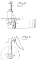
- Figure 3 illustrates part of a cylindrical feeder in an open position; and
- Figure 4 is a top view of the cylindrical feeder shown in Figure 3.
- Figures 1 and 2 illustrate a vegetable cutting machine in which the invention is applied. The illustrated machine comprises a cylindrical feeder 1 which includes a vertical upstanding
cylindrical tube 2 and a vegetable press-feed device in the form of a plate 4 which extends perpendicular to the longitudinal axis of thetube 2 and which can move linearly in relation to the tube. The plate 4 is carried by a stand-arm unit 5 which includes anupper arm 6 having a downwardly extendingshaft 7. Theshaft 7 coacts with atubular part 8 on alower arm 9 of the arm-unit, thereby enabling the plate to be swung away from the upper orifice of the tube, so as to enable vegetables to be inserted into the tube for disintegration in the machine. The plate is shown in its extreme outwardly swung position in Figure 3. The plate can be swung from this illustrated position to a position in which the plate is concentrical with thetube 2. When the plate occupies this latter position, the plate can be moved linearly within the tube. The plate may either be moved manually or with the aid of a pneumatic piston-cylinder device. The plate is moved by means of ashaft 10 which runs in asleeve 11 on theupper frame arm 6. - Although not shown, a machine of this kind is provided adjacent the bottom orifice of the tube with a cutting tool comprising a cutting disc provided with one or more knives.
- In accordance with the invention, the
bottom arm 9 of the arm-unit is provided with an L-shaped slot 12 which penetrates the wall of said arm. The slot has a part which extends parallel with the longitudinal axis of the stand arm-unit upper end 13 of thebottom arm 9. Mounted on theshaft 7 of thetop arm 6 is an outwardly projectingpeg 14 which coacts with the slot. Theupper arm 6 is provided with an outwardly projectingwing 15 which is intended to limit rotary movement of theupper arm 6 to a first position, by coaction with astop block 16. This position is shown in Figures 1 and 2. The two parts of the cylindrical feeder, namely thetube 2 and the vegetable press-feed device are herewith locked together. - The
stop block 16 can be moved against the action of a spring, for instance ahelical spring 17, so that thewing 15 on the upper arm is able to pass over thestop block 16, thereby enabling theupper arm 6 to be rotated to a second position past said first position. In this second position, thepeg 14 is located in a position in which it can run in that part of the L-shaped slot 12 which extends parallel to the longitudinal axis of the stand arm. This position is shown in Figures 3 and 4. In this position, the vegetable press-feed device can be lifted straight up so that thearm 5 will leave thelower arm 9. - The L-shaped slot is configured so that, in coaction with the
peg 14, the plate 4 will be positioned concentrically with thetube 2 when theupper arm 6 is rotated to an opposite position relative to the position shown in Figure 3, in which thepeg 14 lies against thewall 19 of the L-shaped slot. - According to one preferred embodiment, the block moves on a profiled
member 18 which projects out from the inner surface of thecylindrical feeder tube 2. - Thus, the cylindrical tube and the vegetable feeding device can be separated from one another very easily, while, at the same time, when combined in a working position, in which the upper stand arm has limited rotational movement between two positions, it is impossible to separate the vegetable press-feed device from the cylindrical tube by rotating said device.
- Although the invention has been described with reference to an exemplifying embodiment thereof, it will be understood that modifications can be made without departing from the scope defined by the claims.
Claims (2)
- A vegetable cutting machine comprising a cylindrical feeder (1) which includes a vertically upstanding cylindrical tube (2) and a vegetable press-feed device (3) in the form of a plate (4) which extends perpendicular to the longitudinal axis of the tube, wherein the plate is carried by a arm unit including an upper stand arm (6) in which the plate is mounted for linear movement along the longitudinal axis of the tube, the upper stand arm (6) having a downwardly projecting shaft (7) placed parallel with the tube, wherein said shaft coacts with a tubular part (8) on a lower stand arm (9), thereby enabling the plate (4) to be swung away from the top orifice of the tube (2) to enable vegetables to be inserted into said tube for disintegration in said machine, and wherein a cutting tool comprising a disc provided with one or more knives is mounted in the vicinity of the bottom orifice of the tube (2), the machine being characterized in that the wall of the lower stand arm (9) is perforated with an L-shaped slot (12) having a part which extends parallel to the longitudinal axis of the shaft (7) and which terminates at the upper end (13) of said lower stand arm; in that the shaft (7) or the upper stand arm (6) is provided with an outwardly projecting peg (14) intended for coaction with said slot; in that the upper arm (6) is provided with an outwardly projecting wing (15) or the like which functions to restrict rotational movement of the upper stand arm to a first position through coaction with a stop block (16) ; in that the stop block can be moved against the action of a spring force such as to enable the upper stand arm to be rotated to a second position past said first position, in which second position the peg (14) is positioned so as to be movable in that part of the L-shaped slot (12) which extends parallel with the longitudinal axis of the shaft (7).
- A machine according to Claim 1, characterized in that the stop block (16) runs on a profiled member (18) projecting from the outer surface of the cylindrical feeder.
Applications Claiming Priority (2)
| Application Number | Priority Date | Filing Date | Title |
|---|---|---|---|
| SE9001239A SE464693B (en) | 1990-04-04 | 1990-04-04 | FEEDING APPARATUS AT THE VEGETABLE CUTTER |
| SE9001239 | 1990-04-04 |
Publications (2)
| Publication Number | Publication Date |
|---|---|
| EP0451125A1 EP0451125A1 (en) | 1991-10-09 |
| EP0451125B1 true EP0451125B1 (en) | 1994-06-01 |
Family
ID=20379097
Family Applications (1)
| Application Number | Title | Priority Date | Filing Date |
|---|---|---|---|
| EP91850078A Expired - Lifetime EP0451125B1 (en) | 1990-04-04 | 1991-03-27 | A feeding device for vegetable cutting machines |
Country Status (6)
| Country | Link |
|---|---|
| US (1) | US5142972A (en) |
| EP (1) | EP0451125B1 (en) |
| AT (1) | ATE106303T1 (en) |
| DE (1) | DE69102190T2 (en) |
| ES (1) | ES2049716T3 (en) |
| SE (1) | SE464693B (en) |
Families Citing this family (6)
| Publication number | Priority date | Publication date | Assignee | Title |
|---|---|---|---|---|
| US5959634A (en) * | 1993-12-09 | 1999-09-28 | Canon Kabushiki Kaisha | Character generating system employing thickening or narrowing of characters |
| USD464537S1 (en) | 2001-10-26 | 2002-10-22 | Daniel P. Healy | Coring machine |
| US7096777B1 (en) | 2001-10-26 | 2006-08-29 | Healy Daniel P | Automated coring machine |
| US7406914B1 (en) | 2004-06-14 | 2008-08-05 | Healy Daniel P | Modular blade assembly for produce peeling and coring |
| US9364019B2 (en) | 2013-01-25 | 2016-06-14 | Daniel P. Healy | Coring apparatus |
| CN109849086A (en) * | 2017-11-30 | 2019-06-07 | 徕卡显微系统(上海)有限公司 | Retracting device and feeding mechanism having the same |
Family Cites Families (13)
| Publication number | Priority date | Publication date | Assignee | Title |
|---|---|---|---|---|
| US419722A (en) * | 1890-01-21 | Michael siersdorfer | ||
| US539664A (en) * | 1895-05-21 | Raisin-seeder | ||
| US943193A (en) * | 1909-03-16 | 1909-12-14 | Wiley I Irwin | Peach pitter and slicer. |
| US2373781A (en) * | 1942-02-27 | 1945-04-17 | Mike Limberis | Mechanical kitchen equipment |
| DE817351C (en) * | 1948-10-02 | 1951-10-18 | Eugen Burger | Device for cutting fruit, potatoes and other fruits |
| US2852053A (en) * | 1954-10-19 | 1958-09-16 | Inez A Berry | Fruit slicer |
| US3150701A (en) * | 1962-09-24 | 1964-09-29 | Ryp Mfg Company | Vegetable dicing machine |
| US3468355A (en) * | 1967-03-06 | 1969-09-23 | Halldemaskiner Ab | Device in machines for cutting foodstuff |
| JPS5839116Y2 (en) * | 1981-08-01 | 1983-09-03 | 浩和商事株式会社 | Cutter device for pineapple pull |
| US4426924A (en) * | 1982-11-02 | 1984-01-24 | Culwell Charles W | Apple corer with safety feature |
| GB2157945A (en) * | 1984-04-27 | 1985-11-06 | Chin Yang Hsieh | Rotary high-speed automatic slicer |
| US4653393A (en) * | 1986-05-27 | 1987-03-31 | Del Monte Corporation | Apparatus for peeling pineapples |
| US5067397A (en) * | 1991-03-28 | 1991-11-26 | Healy Daniel P | Pineapple cutting and coring device |
-
1990
- 1990-04-04 SE SE9001239A patent/SE464693B/en not_active IP Right Cessation
-
1991
- 1991-03-27 ES ES91850078T patent/ES2049716T3/en not_active Expired - Lifetime
- 1991-03-27 EP EP91850078A patent/EP0451125B1/en not_active Expired - Lifetime
- 1991-03-27 AT AT91850078T patent/ATE106303T1/en not_active IP Right Cessation
- 1991-03-27 DE DE69102190T patent/DE69102190T2/en not_active Expired - Fee Related
- 1991-04-01 US US07/678,734 patent/US5142972A/en not_active Expired - Lifetime
Also Published As
| Publication number | Publication date |
|---|---|
| DE69102190T2 (en) | 1994-12-08 |
| SE9001239D0 (en) | 1990-04-04 |
| SE464693B (en) | 1991-06-03 |
| ES2049716T1 (en) | 1994-05-01 |
| US5142972A (en) | 1992-09-01 |
| ES2049716T3 (en) | 1994-07-16 |
| EP0451125A1 (en) | 1991-10-09 |
| DE69102190D1 (en) | 1994-07-07 |
| ATE106303T1 (en) | 1994-06-15 |
Similar Documents
| Publication | Publication Date | Title |
|---|---|---|
| US6003217A (en) | Size-in-store pleated shade and method and apparatus of sizing | |
| CA1139199A (en) | Feed tube protector for a food processor | |
| US4674690A (en) | Feed tube protector retaining apparatus | |
| DE3650216T2 (en) | Rotating food slicer. | |
| US5040444A (en) | Saw blade position setting apparatus | |
| EP0954415B1 (en) | Food product slicer having an interlock mechanism | |
| US20050276669A1 (en) | Punch assembly with spinning head | |
| US6739066B2 (en) | Level adjusting apparatus for a power tool | |
| EP0901891A1 (en) | Food product slicer having an interlock mechanism | |
| WO1997021526A9 (en) | Food product slicer having an interlock mechanism | |
| EP0451125A1 (en) | A feeding device for vegetable cutting machines | |
| CA2459461A1 (en) | Blind cutting center with detachable vacuum bag | |
| CA2724730C (en) | Automatically configurable blind cutting center | |
| US5529005A (en) | Towel cloth drawing-out device | |
| GB2258686A (en) | Pleated shade | |
| CN110509598A (en) | Multifunctional visual recognition cutting head | |
| US4641826A (en) | Machine designed to lift a flexible, flat workpiece off a support surface | |
| DE3627276A1 (en) | CUTTING INSERT FOR A WORKER OF A KITCHEN MACHINE | |
| CN113522466A (en) | Grinding instrument | |
| EP2877070A1 (en) | Disk grater | |
| EP3114935B1 (en) | Automatic cutting apparatus, applicable to presses for making pasta or to extruders for making snacks | |
| EP1878526A1 (en) | Wood processing machine | |
| US318556A (en) | Device for trimming wall-paper | |
| CN212441462U (en) | Grinding instrument | |
| US2126380A (en) | Slicing machine |
Legal Events
| Date | Code | Title | Description |
|---|---|---|---|
| PUAI | Public reference made under article 153(3) epc to a published international application that has entered the european phase |
Free format text: ORIGINAL CODE: 0009012 |
|
| AK | Designated contracting states |
Kind code of ref document: A1 Designated state(s): AT BE CH DE DK ES FR GB GR IT LI LU NL SE |
|
| 17P | Request for examination filed |
Effective date: 19920319 |
|
| 17Q | First examination report despatched |
Effective date: 19930917 |
|
| GRAA | (expected) grant |
Free format text: ORIGINAL CODE: 0009210 |
|
| ITF | It: translation for a ep patent filed | ||
| AK | Designated contracting states |
Kind code of ref document: B1 Designated state(s): AT BE CH DE DK ES FR GB GR IT LI LU NL SE |
|
| PG25 | Lapsed in a contracting state [announced via postgrant information from national office to epo] |
Ref country code: AT Effective date: 19940601 Ref country code: GR Free format text: LAPSE BECAUSE OF FAILURE TO SUBMIT A TRANSLATION OF THE DESCRIPTION OR TO PAY THE FEE WITHIN THE PRESCRIBED TIME-LIMIT Effective date: 19940601 Ref country code: DK Effective date: 19940601 Ref country code: BE Effective date: 19940601 Ref country code: NL Effective date: 19940601 |
|
| REF | Corresponds to: |
Ref document number: 106303 Country of ref document: AT Date of ref document: 19940615 Kind code of ref document: T |
|
| REF | Corresponds to: |
Ref document number: 69102190 Country of ref document: DE Date of ref document: 19940707 |
|
| ET | Fr: translation filed | ||
| REG | Reference to a national code |
Ref country code: ES Ref legal event code: FG2A Ref document number: 2049716 Country of ref document: ES Kind code of ref document: T3 |
|
| PG25 | Lapsed in a contracting state [announced via postgrant information from national office to epo] |
Ref country code: SE Effective date: 19940901 |
|
| NLV1 | Nl: lapsed or annulled due to failure to fulfill the requirements of art. 29p and 29m of the patents act | ||
| PG25 | Lapsed in a contracting state [announced via postgrant information from national office to epo] |
Ref country code: LU Free format text: LAPSE BECAUSE OF NON-PAYMENT OF DUE FEES Effective date: 19950331 |
|
| PLBE | No opposition filed within time limit |
Free format text: ORIGINAL CODE: 0009261 |
|
| STAA | Information on the status of an ep patent application or granted ep patent |
Free format text: STATUS: NO OPPOSITION FILED WITHIN TIME LIMIT |
|
| 26N | No opposition filed | ||
| REG | Reference to a national code |
Ref country code: GB Ref legal event code: IF02 |
|
| PGFP | Annual fee paid to national office [announced via postgrant information from national office to epo] |
Ref country code: DE Payment date: 20070323 Year of fee payment: 17 |
|
| REG | Reference to a national code |
Ref country code: CH Ref legal event code: PCAR Free format text: ISLER & PEDRAZZINI AG;POSTFACH 1772;8027 ZUERICH (CH) |
|
| PGFP | Annual fee paid to national office [announced via postgrant information from national office to epo] |
Ref country code: CH Payment date: 20080314 Year of fee payment: 18 Ref country code: ES Payment date: 20080318 Year of fee payment: 18 |
|
| PGFP | Annual fee paid to national office [announced via postgrant information from national office to epo] |
Ref country code: GB Payment date: 20080317 Year of fee payment: 18 |
|
| PGFP | Annual fee paid to national office [announced via postgrant information from national office to epo] |
Ref country code: FR Payment date: 20080229 Year of fee payment: 18 |
|
| PGFP | Annual fee paid to national office [announced via postgrant information from national office to epo] |
Ref country code: IT Payment date: 20080329 Year of fee payment: 18 |
|
| PG25 | Lapsed in a contracting state [announced via postgrant information from national office to epo] |
Ref country code: DE Free format text: LAPSE BECAUSE OF NON-PAYMENT OF DUE FEES Effective date: 20081001 |
|
| REG | Reference to a national code |
Ref country code: CH Ref legal event code: PL |
|
| GBPC | Gb: european patent ceased through non-payment of renewal fee |
Effective date: 20090327 |
|
| PG25 | Lapsed in a contracting state [announced via postgrant information from national office to epo] |
Ref country code: LI Free format text: LAPSE BECAUSE OF NON-PAYMENT OF DUE FEES Effective date: 20090331 Ref country code: CH Free format text: LAPSE BECAUSE OF NON-PAYMENT OF DUE FEES Effective date: 20090331 |
|
| PG25 | Lapsed in a contracting state [announced via postgrant information from national office to epo] |
Ref country code: GB Free format text: LAPSE BECAUSE OF NON-PAYMENT OF DUE FEES Effective date: 20090327 |
|
| REG | Reference to a national code |
Ref country code: ES Ref legal event code: FD2A Effective date: 20090328 |
|
| PG25 | Lapsed in a contracting state [announced via postgrant information from national office to epo] |
Ref country code: ES Free format text: LAPSE BECAUSE OF NON-PAYMENT OF DUE FEES Effective date: 20090328 |
|
| PG25 | Lapsed in a contracting state [announced via postgrant information from national office to epo] |
Ref country code: IT Free format text: LAPSE BECAUSE OF NON-PAYMENT OF DUE FEES Effective date: 20090327 |
|
| REG | Reference to a national code |
Ref country code: FR Ref legal event code: ST Effective date: 20110916 |
|
| PG25 | Lapsed in a contracting state [announced via postgrant information from national office to epo] |
Ref country code: FR Free format text: LAPSE BECAUSE OF NON-PAYMENT OF DUE FEES Effective date: 20090331 |