EP0450974A2 - Transmission congestion control method and apparatus - Google Patents
Transmission congestion control method and apparatus Download PDFInfo
- Publication number
- EP0450974A2 EP0450974A2 EP91303017A EP91303017A EP0450974A2 EP 0450974 A2 EP0450974 A2 EP 0450974A2 EP 91303017 A EP91303017 A EP 91303017A EP 91303017 A EP91303017 A EP 91303017A EP 0450974 A2 EP0450974 A2 EP 0450974A2
- Authority
- EP
- European Patent Office
- Prior art keywords
- queue
- queues
- data
- communications link
- polled
- Prior art date
- Legal status (The legal status is an assumption and is not a legal conclusion. Google has not performed a legal analysis and makes no representation as to the accuracy of the status listed.)
- Granted
Links
- 238000000034 method Methods 0.000 title claims abstract description 9
- 230000005540 biological transmission Effects 0.000 title claims description 4
- 239000000835 fiber Substances 0.000 claims description 3
- 238000012544 monitoring process Methods 0.000 claims 4
- 238000010586 diagram Methods 0.000 description 3
- 230000011664 signaling Effects 0.000 description 1
- 230000001360 synchronised effect Effects 0.000 description 1
Images

Classifications
-
- H—ELECTRICITY
- H04—ELECTRIC COMMUNICATION TECHNIQUE
- H04J—MULTIPLEX COMMUNICATION
- H04J3/00—Time-division multiplex systems
- H04J3/24—Time-division multiplex systems in which the allocation is indicated by an address the different channels being transmitted sequentially
- H04J3/247—ATM or packet multiplexing
-
- H—ELECTRICITY
- H04—ELECTRIC COMMUNICATION TECHNIQUE
- H04J—MULTIPLEX COMMUNICATION
- H04J3/00—Time-division multiplex systems
- H04J3/16—Time-division multiplex systems in which the time allocation to individual channels within a transmission cycle is variable, e.g. to accommodate varying complexity of signals, to vary number of channels transmitted
- H04J3/1682—Allocation of channels according to the instantaneous demands of the users, e.g. concentrated multiplexers, statistical multiplexers
Definitions
- This invention relates generally to communications systems and, more particularly, to congestion control in communications systems.
- High speed communications links are typically utilized to transmit data from a plurality of lower speed channels.
- data from each of the plurality of lower speed channels is stored temporarily in an associated queue, and the queues are serviced sequentially, for example, by a time-division multiplexer or a switch.
- the multiplexer may not be able to service this queue fast enough. Since the queue is of finite capacity, data overflow would occur. This data overflow condition is known as congestion.
- each terminal is allowed to transmit as much data in as short a time as is required by the terminal.
- Congestion is controlled in such prior arrangements by sending a control message to the terminal if congestion occurs. This control message inhibits transmission from the terminal and thereby avoids congestion.
- This arrangement does not function well in high speed networks because it is quite likely that by the time the control message can be generated and transmitted to the terminal, congestion has already occurred and data has been lost.
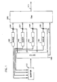
- FIG.1 shows a block diagram of an exemplary embodiment of the invention comprising switch 100, a plurality of queues 101-104, an exemplary time division multiplexer (TDM) 105, communications link 111, and monitor 112.
- TDM time division multiplexer
- communications link 111 is divided into an exemplary five channels, and that each of multiplexer inputs 106-110 is associated with a separate one of the five channels.
- any desired number of communications channels may be employed on communications link 111.
- each of the four queues 101-104 is polled for a predetermined amount of time, denoted a polling time.
- multiplexer input 110 is polled for a polling time during each polling cycle.
- each polling cycle comprises five polling times, one for each of the four exemplary queues 101-104, and a final polling time for multiplexer input 110.
- time division multiplexer 105 sequentially polls the queues 101-104 in a predetermined order in well-known fashion.
- data in the particular one of queues 101-104 is supplied to the corresponding multiplexer input 106-109, respectively, and transmitted on the associated channel of communications link 111.
- monitor 112 stores a record of the fullness of each queue. This fullness represents how near the queue is to a data overflow condition and may be, for example, the percentage of the queue which is occupied by data. Monitor 112 also records the address of the particular queue being polled.
- monitor 112 Since monitor 112 is arranged to monitor the particular queue being polled, it is necessary to keep monitor 112 synchronized with multiplexer 105. This is readily achieved by, for example, deriving the clock for monitor 112 from the clock which is employed by multiplexer 105.
- monitor 112 After queues 101-104 have been polled, monitor 112 contains the address of the one of queues 101-104 which is nearest to a data overflow condition. Monitor 112 then supplies a control signal to switch 100. This control signal causes switch 100 to connect the one of queues 101-104 which is nearest to a data overflow condition to multiplexer input 110. Thus, the fifth polling time in each polling cycle is used for whichever queue is nearest to a data overflow condition.
- multiplexer 105 input 110 may be utilized to transmit data from a different one of the four queues 101-104 in each polling cycle. Specifically, whichever one of queues 101-104 is nearest to a data overflow condition during a polling cycle will be switched to multiplexer input 110 during the fifth polling time of that polling cycle.
- queue 103 receives a sudden burst of data and, thereby becomes very near to a data overflow condition.
- queue 103 would be serviced twice in a polling cycle, since it would be nearest to a data overflow condition and would thereby be connected via switch 100 to multiplexer input 110. This servicing of queue 103 twice in a polling cycle continues until queue 103 is no longer nearer to the data overflow condition than queues 101, 102, and 104.
- FIG. 2 shows a flow chart depicting operational steps of an exemplary algorithm which may be implemented in monitor 112.
- "i" denotes the address of the particular one of queues 101-104 currently being polled
- the fullness denotes the percentage of the queue which is occupied by data, for example, packets.
- queues 101-104 are assumed to be at addresses 1-4, respectively.
- the "fullness" of queue 101 is written to monitor 112 by step 202.
- Step 203 compares the fullness written in, to the fullness stored, which is initially zero. If the written in fullness is greater, step 204 will replace the stored fullness with the written in fullness. Additionally, step 204 will replace the stored address with the address of the ith queue. If however, the written in fullness is less than or equal to the stored fullness, then the stored fullness and address will not be updated.
- the technique will not alleviate congestion completely. If a particular queue continues to receive data at a higher rate than the data can be transmitted on the associated channel of communications link 111, then that queue will eventually experience data overflow. The technique does however, delay the occurrence of overflow so that sufficient time exists to signal the source of the data thereby slow or stop transmission. It should also be noted that while an extra channel is utilized to control congestion, such extra channel is never held idle when no congestion exists. Rather, as can be appreciated from the above discussion, such extra channel is utilized in every polling cycle, and is dynamically allocated to whichever queue is nearest to a data overflow condition in that particular polling cycle.
- the receiving terminal would have to switch data from the channel associated with input 110 of multiplexer 105 to an associated destination.
- an address in the packet header could be utilized to accomplish this function at the receiver in accordance with well known techniques.
- out-of-band signalling could be utilized.
- the communications link could actually be several physical connections, one or more of which are used for whichever queue requires them.
- the communications link could be fiber optic, in order to facilitate high speed.
Landscapes
- Engineering & Computer Science (AREA)
- Computer Networks & Wireless Communication (AREA)
- Signal Processing (AREA)
- Computer Hardware Design (AREA)
- Data Exchanges In Wide-Area Networks (AREA)
- Time-Division Multiplex Systems (AREA)
- Mobile Radio Communication Systems (AREA)
Abstract
Description
- This invention relates generally to communications systems and, more particularly, to congestion control in communications systems.
- High speed communications links are typically utilized to transmit data from a plurality of lower speed channels. Usually, data from each of the plurality of lower speed channels is stored temporarily in an associated queue, and the queues are serviced sequentially, for example, by a time-division multiplexer or a switch. Consider the situation where one of the queues suddenly receives a large burst of data. The multiplexer may not be able to service this queue fast enough. Since the queue is of finite capacity, data overflow would occur. This data overflow condition is known as congestion.
- Several arrangements have previously been employed in attempts to overcome the problem of congestion. One such arrangement is disclosed in the article "Congestion Control Through Input Rate Regulation", by M. Sidi et al. in IEEE GLOBECOM 1989. In the Sidi article, a plurality of terminals are connected to a network, and each terminal is assigned a predetermined maximum input data rate. Congestion is controlled by dropping data if the data input rate of the terminal exceeds the predetermined maximum input rate. Alternatively, the input of data can be temporarily halted until a later time. The problem with this arrangement is that a determination of resource requirements must be made for each terminal in advance of operation. Since this prior determination cannot be made accurately, one must account for the worst possible case. This results in reserving more network resources for a particular terminal than is normally needed, leading to underutilized resources.
- In other prior arrangements, each terminal is allowed to transmit as much data in as short a time as is required by the terminal. Congestion is controlled in such prior arrangements by sending a control message to the terminal if congestion occurs. This control message inhibits transmission from the terminal and thereby avoids congestion. This arrangement does not function well in high speed networks because it is quite likely that by the time the control message can be generated and transmitted to the terminal, congestion has already occurred and data has been lost.
- These and other problems in prior congestion control arrangements are overcome by employing a plurality of at most N-1 queues, a N channel communications link, and a multiplexer for multiplexing the channels onto the communications link. The plurality of at most N-1 queues are sequentially polled. During the time that a queue is polled, data from that queue is supplied as an output onto an associated one of the N channels of the communications link, thereby leaving at least one remaining channel after all the queues have been polled. Simultaneously with the polling, the queues are monitored to determine which one or more of the queues is nearest to a data overflow condition, i.e., has the most data stored therein relative to the other queues. After the at most N-1 queues have been polled and monitored, data from the one or more queues which is nearest to a data overflow condition is transmitted on the at least one remaining channel. In this manner, and in accordance with the invention, the extra channel is automatically provided to the most heavily loaded channel and its cost is shared by all channels.
- In the Drawing:
- FIG. 1 shows a simplified block diagram of a portion of a communications system including an exemplary embodiment of the invention; and
- FIG. 2 shows a flow diagram depicting operational steps of an exemplary implementation of the monitor employed in the embodiment of FIG. 1.
- FIG.1 shows a block diagram of an exemplary embodiment of the
invention comprising switch 100, a plurality of queues 101-104, an exemplary time division multiplexer (TDM) 105,communications link 111, andmonitor 112. For simplicity and clarity of description, it is assumed thatcommunications link 111 is divided into an exemplary five channels, and that each of multiplexer inputs 106-110 is associated with a separate one of the five channels. However, it will be apparent to those of ordinary skill in the art that any desired number of communications channels may be employed oncommunications link 111. During a polling cycle, each of the four queues 101-104 is polled for a predetermined amount of time, denoted a polling time. Additionally, multiplexer input 110 is polled for a polling time during each polling cycle. Thus, each polling cycle comprises five polling times, one for each of the four exemplary queues 101-104, and a final polling time for multiplexer input 110. - In operation, time division multiplexer 105 sequentially polls the queues 101-104 in a predetermined order in well-known fashion. During the polling time for each of queues 101-104, data in the particular one of queues 101-104 is supplied to the corresponding multiplexer input 106-109, respectively, and transmitted on the associated channel of
communications link 111. In addition, during the polling time for each one of queues 101-104, monitor 112 stores a record of the fullness of each queue. This fullness represents how near the queue is to a data overflow condition and may be, for example, the percentage of the queue which is occupied by data. Monitor 112 also records the address of the particular queue being polled. - Since
monitor 112 is arranged to monitor the particular queue being polled, it is necessary to keepmonitor 112 synchronized withmultiplexer 105. This is readily achieved by, for example, deriving the clock formonitor 112 from the clock which is employed bymultiplexer 105. - After queues 101-104 have been polled,
monitor 112 contains the address of the one of queues 101-104 which is nearest to a data overflow condition. Monitor 112 then supplies a control signal to switch 100. This control signal causesswitch 100 to connect the one of queues 101-104 which is nearest to a data overflow condition to multiplexer input 110. Thus, the fifth polling time in each polling cycle is used for whichever queue is nearest to a data overflow condition. - From the above discussion, it can be appreciated that
multiplexer 105 input 110 may be utilized to transmit data from a different one of the four queues 101-104 in each polling cycle. Specifically, whichever one of queues 101-104 is nearest to a data overflow condition during a polling cycle will be switched to multiplexer input 110 during the fifth polling time of that polling cycle. - In the above manner, congestion in the network is slowed. More particularly, assume
queue 103, for example, receives a sudden burst of data and, thereby becomes very near to a data overflow condition. As can be seen from the above discussion,queue 103 would be serviced twice in a polling cycle, since it would be nearest to a data overflow condition and would thereby be connected viaswitch 100 to multiplexer input 110. This servicing ofqueue 103 twice in a polling cycle continues untilqueue 103 is no longer nearer to the data overflow condition thanqueues - FIG. 2 shows a flow chart depicting operational steps of an exemplary algorithm which may be implemented in
monitor 112. In FIG. 2, "i" denotes the address of the particular one of queues 101-104 currently being polled, and the fullness denotes the percentage of the queue which is occupied by data, for example, packets. For purposes of explanation, queues 101-104 are assumed to be at addresses 1-4, respectively. - The algorithm is entered via
step 200. At the start of a polling cycle,step 201 sets i=1, corresponding toqueue 101, and fullness=0, corresponding to an empty queue. As thefirst queue 101 is polled bytime division multiplexer 105, the "fullness" ofqueue 101 is written to monitor 112 bystep 202.Step 203 then compares the fullness written in, to the fullness stored, which is initially zero. If the written in fullness is greater,step 204 will replace the stored fullness with the written in fullness. Additionally,step 204 will replace the stored address with the address of the ith queue. If however, the written in fullness is less than or equal to the stored fullness, then the stored fullness and address will not be updated. - Next,
step 205 determines if all the queues have been polled for the current polling cycle. If they have not all been polled, step 206 will increment the queue address i, i.e. i=i+1. Steps 202-205 are then repeated as shown in FIG. 2. Thus, it can be appreciated that after the queues have all been polled, the address of the most full queue, and its fullness, are stored inmonitor 112. After the last queue is polled,step 207 sends a control signal to switch 100. This control signal causes switch 100 to connect the queue which is nearest to a data overflow condition, i.e., the most full, to multiplexer input 110, thereby servicing this queue two times in the polling cycle. The algorithm then returns to step 201 for the start of the next polling cycle. - Several further points about the operation of this embodiment of the invention are worth noting. First, the technique will not alleviate congestion completely. If a particular queue continues to receive data at a higher rate than the data can be transmitted on the associated channel of communications link 111, then that queue will eventually experience data overflow. The technique does however, delay the occurrence of overflow so that sufficient time exists to signal the source of the data thereby slow or stop transmission. It should also be noted that while an extra channel is utilized to control congestion, such extra channel is never held idle when no congestion exists. Rather, as can be appreciated from the above discussion, such extra channel is utilized in every polling cycle, and is dynamically allocated to whichever queue is nearest to a data overflow condition in that particular polling cycle.
- It should also be noted that the receiving terminal would have to switch data from the channel associated with input 110 of
multiplexer 105 to an associated destination. In a packet system, an address in the packet header could be utilized to accomplish this function at the receiver in accordance with well known techniques. In other systems, out-of-band signalling could be utilized. - It is to be understood that the example given above is for illustrative purposes only and is not to be construed as limiting the scope or spirit of the invention. Other variations may be constructed by those ordinary skill in the art. For example, more than one extra channel could be employed. The communications link could actually be several physical connections, one or more of which are used for whichever queue requires them. The communications link could be fiber optic, in order to facilitate high speed.
Claims (7)
- A method of controlling transmission congestion in apparatus for generating a plurality of N communications channels (106-110), CHARACTERISED IN THAT the apparatus comprises a plurality of at most N-1 queues (101-104); and the method comprises the steps of:(a) polling one of the queues, and transmitting data therefrom on an associated separate one of the N channels during such time when the queue is polled,(b) repeating step (a) for each of the plurality of at most N-1 queues, thereby leaving at least one remaining channel (110),(c) determining at least one queue which has the most data stored therein relative to the queues′ condition and outputting data therefrom on said at least one remaining channel, and(d) repeating steps (a) to (c).
- A method as claimed in claim 1 wherein the communications link is a fiber optic communications link (111).
- A method as claimed in claim 1 or 2 wherein step (c) comprises monitoring a fullness associated with each queue, recording an address associated with a queue which is most full, generating a control signal in response to the recorded address, transmitting the control signal to a switch (100), and switching data from the queue associated with the recorded address to the communications link via the switch.
- Apparatus for generating a plurality of N communications channels (106-110), and being adapted for connection to a communications link (111), CHARACTERISED BY a plurality of at most N-1 queues (101-104), means (105) for sequentially polling said queues and for outputting data from each queue on an associated separate one of said N communications channels during such time when said queue is polled, thereby leaving at least one remaining communications channel (110), means (112) for monitoring each of said queues to determine at least one of said queues which has the most data stored therein relative to the other queues, and means (100) for switching data from said at least one queue which has the most data stored therein to said means for sequentially polling and for outputting, thereby causing data from said at least one queue which has the most data stored therein to be output on said at least one remaining channel.
- Apparatus as claimed in claim 4 wherein said communications link is a fiber optic communications link.
- Apparatus as claimed in claim 4 or 5 wherein the means for monitoring includes means for monitoring a fullness associated with each queue, and for recording an address associated with a queue which is most full.
- Apparatus as claimed in claim 4, 5 or 6 wherein the means for sequentially polling comprises a Time Division Multiplexer comprising a plurality of inputs, each arranged to receive data from a separate one of the N-1 queues.
Applications Claiming Priority (2)
| Application Number | Priority Date | Filing Date | Title |
|---|---|---|---|
| US07/505,796 US5048013A (en) | 1990-04-06 | 1990-04-06 | Transmission congestion control method and apparatus |
| US505796 | 1990-04-06 |
Publications (3)
| Publication Number | Publication Date |
|---|---|
| EP0450974A2 true EP0450974A2 (en) | 1991-10-09 |
| EP0450974A3 EP0450974A3 (en) | 1992-09-23 |
| EP0450974B1 EP0450974B1 (en) | 1996-08-14 |
Family
ID=24011870
Family Applications (1)
| Application Number | Title | Priority Date | Filing Date |
|---|---|---|---|
| EP91303017A Expired - Lifetime EP0450974B1 (en) | 1990-04-06 | 1991-04-05 | Transmission congestion control method and apparatus |
Country Status (5)
| Country | Link |
|---|---|
| US (1) | US5048013A (en) |
| EP (1) | EP0450974B1 (en) |
| JP (1) | JPH0828741B2 (en) |
| CA (1) | CA2039746C (en) |
| DE (1) | DE69121273T2 (en) |
Cited By (1)
| Publication number | Priority date | Publication date | Assignee | Title |
|---|---|---|---|---|
| FR2728122A1 (en) * | 1994-12-13 | 1996-06-14 | Alcatel Espace | ADAPTIVE PACKET MULTIPLEXING SYSTEM BY CALCULATION OF DYNAMIC TIMES |
Families Citing this family (14)
| Publication number | Priority date | Publication date | Assignee | Title |
|---|---|---|---|---|
| GB8914983D0 (en) * | 1989-06-29 | 1989-08-23 | Digital Equipment Int | Congestion control in computer networks |
| US5475680A (en) * | 1989-09-15 | 1995-12-12 | Gpt Limited | Asynchronous time division multiplex switching system |
| IT1237668B (en) * | 1989-10-31 | 1993-06-15 | Telettra Lab Telefon | SYSTEM AND MULTIPLATOR / DEMULTIPLATOR FOR THE TRANSMISSION / RECEPTION OF DIGITAL TELEVISION INFORMATION. |
| JP2752522B2 (en) * | 1990-12-20 | 1998-05-18 | 富士通株式会社 | Flow control method in broadband ISDN |
| US5233606A (en) * | 1991-08-02 | 1993-08-03 | At&T Bell Laboratories | Arrangement for controlling shared-buffer-memory overflow in a multi-priority environment |
| NL9201668A (en) * | 1992-09-25 | 1994-04-18 | Nederland Ptt | Method for converting a polling frequency table into a polling sequence table. |
| US5701301A (en) * | 1993-06-28 | 1997-12-23 | Bellsouth Corporation | Mediation of open advanced intelligent network in SS7 protocol open access environment |
| US5457679A (en) * | 1993-12-08 | 1995-10-10 | At&T Corp. | Channel sharing and memory sharing in a packet switching system |
| US5596577A (en) * | 1995-05-02 | 1997-01-21 | Motorola, Inc. | Method and system for providing access by secondary stations to a shared transmission medium |
| KR100318956B1 (en) * | 1995-12-26 | 2002-04-22 | 윤종용 | Apparatus and method for multiplexing cells in asynchronous transmission mode |
| KR100318957B1 (en) | 1996-09-02 | 2002-04-22 | 윤종용 | Congestion notification device and congestion control method in asynchronous transmission mode network |
| JPH10229444A (en) * | 1997-02-13 | 1998-08-25 | Nec Corp | Optimum call distribution method and system using intelligent network |
| US5742587A (en) * | 1997-02-28 | 1998-04-21 | Lanart Corporation | Load balancing port switching hub |
| US6625117B1 (en) * | 1999-09-30 | 2003-09-23 | International Business Machines Corporation | Method and apparatus for switching messages from a primary message channel to a secondary message channel in a message queuing system |
Citations (3)
| Publication number | Priority date | Publication date | Assignee | Title |
|---|---|---|---|---|
| EP0169017A2 (en) * | 1984-07-16 | 1986-01-22 | AT&T Corp. | Method for controlling information transfer |
| US4821264A (en) * | 1988-02-04 | 1989-04-11 | Bell Communications Research, Inc. | Adaptive concentration communication network ISDN access |
| US4914650A (en) * | 1988-12-06 | 1990-04-03 | American Telephone And Telegraph Company | Bandwidth allocation and congestion control scheme for an integrated voice and data network |
Family Cites Families (5)
| Publication number | Priority date | Publication date | Assignee | Title |
|---|---|---|---|---|
| US4538259A (en) * | 1983-07-05 | 1985-08-27 | International Business Machines Corporation | System for digitized voice and data with means to compensate for variable path delays |
| JPS6336348A (en) * | 1986-07-30 | 1988-02-17 | Toshiba Corp | Buffer memory control method |
| US4914653A (en) * | 1986-12-22 | 1990-04-03 | American Telephone And Telegraph Company | Inter-processor communication protocol |
| US4916692A (en) * | 1988-03-14 | 1990-04-10 | Racal Data Communications Inc. | TDM bus controller |
| US4962497A (en) * | 1989-09-21 | 1990-10-09 | At&T Bell Laboratories | Building-block architecture of a multi-node circuit-and packet-switching system |
-
1990
- 1990-04-06 US US07/505,796 patent/US5048013A/en not_active Expired - Lifetime
-
1991
- 1991-04-04 CA CA002039746A patent/CA2039746C/en not_active Expired - Fee Related
- 1991-04-05 DE DE69121273T patent/DE69121273T2/en not_active Expired - Fee Related
- 1991-04-05 JP JP9975791A patent/JPH0828741B2/en not_active Expired - Fee Related
- 1991-04-05 EP EP91303017A patent/EP0450974B1/en not_active Expired - Lifetime
Patent Citations (3)
| Publication number | Priority date | Publication date | Assignee | Title |
|---|---|---|---|---|
| EP0169017A2 (en) * | 1984-07-16 | 1986-01-22 | AT&T Corp. | Method for controlling information transfer |
| US4821264A (en) * | 1988-02-04 | 1989-04-11 | Bell Communications Research, Inc. | Adaptive concentration communication network ISDN access |
| US4914650A (en) * | 1988-12-06 | 1990-04-03 | American Telephone And Telegraph Company | Bandwidth allocation and congestion control scheme for an integrated voice and data network |
Non-Patent Citations (1)
| Title |
|---|
| AUTOMATIC CONTROL AND COMPUTER SCIENCES, vol. 21, no. 4, April 1987, NEW YORK, US; pages 24 - 29; V. B. IVANOVSKII: 'MESSAGE SWITCHING NETWORK WITH BACKUP CHANNELS' * |
Cited By (3)
| Publication number | Priority date | Publication date | Assignee | Title |
|---|---|---|---|---|
| FR2728122A1 (en) * | 1994-12-13 | 1996-06-14 | Alcatel Espace | ADAPTIVE PACKET MULTIPLEXING SYSTEM BY CALCULATION OF DYNAMIC TIMES |
| EP0717519A1 (en) * | 1994-12-13 | 1996-06-19 | Alcatel N.V. | Adaptive packet multiplexing system with calculation of dynamic delivery times |
| US5784376A (en) * | 1994-12-13 | 1998-07-21 | Alcatel N.V. | Adaptive burst multiplexing system using dynamic deadline computation |
Also Published As
| Publication number | Publication date |
|---|---|
| DE69121273D1 (en) | 1996-09-19 |
| CA2039746C (en) | 1994-06-21 |
| JPH04227357A (en) | 1992-08-17 |
| JPH0828741B2 (en) | 1996-03-21 |
| CA2039746A1 (en) | 1991-10-07 |
| US5048013A (en) | 1991-09-10 |
| DE69121273T2 (en) | 1997-03-06 |
| EP0450974B1 (en) | 1996-08-14 |
| EP0450974A3 (en) | 1992-09-23 |
Similar Documents
| Publication | Publication Date | Title |
|---|---|---|
| CA2119205C (en) | Improvements in or relating to asynchronous transfer mode communication systems | |
| US5048013A (en) | Transmission congestion control method and apparatus | |
| EP0297629B1 (en) | Communications systems | |
| US5577035A (en) | Apparatus and method of processing bandwidth requirements in an ATM switch | |
| JP4209940B2 (en) | Broadband switching network | |
| US5467348A (en) | Bandwidth allocation system of virtual path in asynchronous transfer mode | |
| EP0596624B1 (en) | Bandwidth allocation, transmission scheduling, and congestion avoidance in broadband asynchronous transfer mode networks | |
| EP0508378B1 (en) | Method and system for monitoring the packet rate in a packet network | |
| US5784358A (en) | Broadband switching network with automatic bandwidth allocation in response to data cell detection | |
| US6091740A (en) | Bandwidth management method and circuit, communication apparatus, communication system, and dual-queue network unit | |
| US5414697A (en) | Data transmission control system | |
| US6560231B1 (en) | Multiplex transmission system and bandwidth control method | |
| EP0706298A2 (en) | Dynamic queue length thresholds in a shared memory ATM switch | |
| JP3645746B2 (en) | Dynamic bandwidth control system for upstream bandwidth in optical communication networks | |
| CA2161359C (en) | Telecommunication system with detection and control of packet collisions | |
| US5365521A (en) | Data transmission and transmission path setting among exchange modules in building block type exchanger | |
| US6542463B1 (en) | Method and arrangement for controlling accesses of network terminal units to predetermined resources of a packet-oriented communication network | |
| JP3092580B2 (en) | Band allocation method and transmission system | |
| US8369320B2 (en) | Multiplexing apparatus and cell discard method | |
| GB2272820A (en) | Improvements in or relating to asynchronous transfer mode communication systems | |
| KR20000006077A (en) | An arrangement for minimizing cell-delay variations in a communications system that supports multiple constant-bit-rate connections | |
| JPH03272248A (en) | Digital communication system | |
| JPH104409A (en) | System consisting of plurality of units and method for controlling information transfer | |
| KR0151920B1 (en) | Atm unit switch control method for abr service | |
| JPH0385839A (en) | Data communication flow control system |
Legal Events
| Date | Code | Title | Description |
|---|---|---|---|
| PUAI | Public reference made under article 153(3) epc to a published international application that has entered the european phase |
Free format text: ORIGINAL CODE: 0009012 |
|
| AK | Designated contracting states |
Kind code of ref document: A2 Designated state(s): DE FR GB IT |
|
| PUAL | Search report despatched |
Free format text: ORIGINAL CODE: 0009013 |
|
| AK | Designated contracting states |
Kind code of ref document: A3 Designated state(s): DE FR GB IT |
|
| 17P | Request for examination filed |
Effective date: 19930311 |
|
| RAP3 | Party data changed (applicant data changed or rights of an application transferred) |
Owner name: AT&T CORP. |
|
| 17Q | First examination report despatched |
Effective date: 19950607 |
|
| GRAH | Despatch of communication of intention to grant a patent |
Free format text: ORIGINAL CODE: EPIDOS IGRA |
|
| GRAA | (expected) grant |
Free format text: ORIGINAL CODE: 0009210 |
|
| AK | Designated contracting states |
Kind code of ref document: B1 Designated state(s): DE FR GB IT |
|
| REF | Corresponds to: |
Ref document number: 69121273 Country of ref document: DE Date of ref document: 19960919 |
|
| ITF | It: translation for a ep patent filed | ||
| ET | Fr: translation filed | ||
| ET | Fr: translation filed | ||
| PLBE | No opposition filed within time limit |
Free format text: ORIGINAL CODE: 0009261 |
|
| STAA | Information on the status of an ep patent application or granted ep patent |
Free format text: STATUS: NO OPPOSITION FILED WITHIN TIME LIMIT |
|
| 26N | No opposition filed | ||
| REG | Reference to a national code |
Ref country code: GB Ref legal event code: IF02 |
|
| PGFP | Annual fee paid to national office [announced via postgrant information from national office to epo] |
Ref country code: DE Payment date: 20060330 Year of fee payment: 16 |
|
| PGFP | Annual fee paid to national office [announced via postgrant information from national office to epo] |
Ref country code: GB Payment date: 20060405 Year of fee payment: 16 |
|
| PGFP | Annual fee paid to national office [announced via postgrant information from national office to epo] |
Ref country code: FR Payment date: 20060410 Year of fee payment: 16 |
|
| PGFP | Annual fee paid to national office [announced via postgrant information from national office to epo] |
Ref country code: IT Payment date: 20060430 Year of fee payment: 16 |
|
| GBPC | Gb: european patent ceased through non-payment of renewal fee |
Effective date: 20070405 |
|
| PG25 | Lapsed in a contracting state [announced via postgrant information from national office to epo] |
Ref country code: DE Free format text: LAPSE BECAUSE OF NON-PAYMENT OF DUE FEES Effective date: 20071101 |
|
| PG25 | Lapsed in a contracting state [announced via postgrant information from national office to epo] |
Ref country code: GB Free format text: LAPSE BECAUSE OF NON-PAYMENT OF DUE FEES Effective date: 20070405 |
|
| PG25 | Lapsed in a contracting state [announced via postgrant information from national office to epo] |
Ref country code: FR Free format text: LAPSE BECAUSE OF NON-PAYMENT OF DUE FEES Effective date: 20070430 |
|
| PG25 | Lapsed in a contracting state [announced via postgrant information from national office to epo] |
Ref country code: IT Free format text: LAPSE BECAUSE OF NON-PAYMENT OF DUE FEES Effective date: 20070405 |