EP0449822B1 - Electronic control and protection device - Google Patents
Electronic control and protection device Download PDFInfo
- Publication number
- EP0449822B1 EP0449822B1 EP89905438A EP89905438A EP0449822B1 EP 0449822 B1 EP0449822 B1 EP 0449822B1 EP 89905438 A EP89905438 A EP 89905438A EP 89905438 A EP89905438 A EP 89905438A EP 0449822 B1 EP0449822 B1 EP 0449822B1
- Authority
- EP
- European Patent Office
- Prior art keywords
- heater
- facade
- protection device
- power source
- enclosure
- Prior art date
- Legal status (The legal status is an assumption and is not a legal conclusion. Google has not performed a legal analysis and makes no representation as to the accuracy of the status listed.)
- Expired - Lifetime
Links
- 230000001747 exhibiting effect Effects 0.000 claims description 2
- 238000010438 heat treatment Methods 0.000 abstract description 10
- 239000011521 glass Substances 0.000 abstract description 3
- 229910052751 metal Inorganic materials 0.000 description 3
- 239000002184 metal Substances 0.000 description 3
- 239000004065 semiconductor Substances 0.000 description 2
- 230000003213 activating effect Effects 0.000 description 1
- 230000002411 adverse Effects 0.000 description 1
- 239000004411 aluminium Substances 0.000 description 1
- 229910052782 aluminium Inorganic materials 0.000 description 1
- XAGFODPZIPBFFR-UHFFFAOYSA-N aluminium Chemical compound [Al] XAGFODPZIPBFFR-UHFFFAOYSA-N 0.000 description 1
- 230000005494 condensation Effects 0.000 description 1
- 238000009833 condensation Methods 0.000 description 1
- 239000004020 conductor Substances 0.000 description 1
- 238000010276 construction Methods 0.000 description 1
- 239000000356 contaminant Substances 0.000 description 1
- 230000000694 effects Effects 0.000 description 1
- 238000009434 installation Methods 0.000 description 1
- 239000000463 material Substances 0.000 description 1
- 150000003839 salts Chemical class 0.000 description 1
- 230000002459 sustained effect Effects 0.000 description 1
Images
Classifications
-
- H—ELECTRICITY
- H02—GENERATION; CONVERSION OR DISTRIBUTION OF ELECTRIC POWER
- H02H—EMERGENCY PROTECTIVE CIRCUIT ARRANGEMENTS
- H02H7/00—Emergency protective circuit arrangements specially adapted for specific types of electric machines or apparatus or for sectionalised protection of cable or line systems, and effecting automatic switching in the event of an undesired change from normal working conditions
- H02H7/22—Emergency protective circuit arrangements specially adapted for specific types of electric machines or apparatus or for sectionalised protection of cable or line systems, and effecting automatic switching in the event of an undesired change from normal working conditions for distribution gear, e.g. bus-bar systems; for switching devices
- H02H7/226—Emergency protective circuit arrangements specially adapted for specific types of electric machines or apparatus or for sectionalised protection of cable or line systems, and effecting automatic switching in the event of an undesired change from normal working conditions for distribution gear, e.g. bus-bar systems; for switching devices for wires or cables, e.g. heating wires
-
- H—ELECTRICITY
- H02—GENERATION; CONVERSION OR DISTRIBUTION OF ELECTRIC POWER
- H02H—EMERGENCY PROTECTIVE CIRCUIT ARRANGEMENTS
- H02H3/00—Emergency protective circuit arrangements for automatic disconnection directly responsive to an undesired change from normal electric working condition with or without subsequent reconnection ; integrated protection
- H02H3/16—Emergency protective circuit arrangements for automatic disconnection directly responsive to an undesired change from normal electric working condition with or without subsequent reconnection ; integrated protection responsive to fault current to earth, frame or mass
-
- H—ELECTRICITY
- H02—GENERATION; CONVERSION OR DISTRIBUTION OF ELECTRIC POWER
- H02H—EMERGENCY PROTECTIVE CIRCUIT ARRANGEMENTS
- H02H7/00—Emergency protective circuit arrangements specially adapted for specific types of electric machines or apparatus or for sectionalised protection of cable or line systems, and effecting automatic switching in the event of an undesired change from normal working conditions
- H02H7/008—Emergency protective circuit arrangements specially adapted for specific types of electric machines or apparatus or for sectionalised protection of cable or line systems, and effecting automatic switching in the event of an undesired change from normal working conditions for protective arrangements according to this subclass
Definitions
- This invention relates to a facade of a building having a thermally conductive framework having a heating element connected to electrical power via an electronic control and protection device.
- ELCBs Earth leakage current breakers
- GB Patent No. 1 208 208 discloses an earth-leakage transformer having a positive temperature coefficient resistor that responds to the heat generated in the coils of the transformer under conditions of sustained overload to operate a trip coil.
- Elongate heating elements including those of the self-regulating type, are not always installed by electrically skilled personnel, so that extra safety must be ensured in the products as sold by the manufacturer.
- One object of the present invention is to provide a facade in which the electronic control and protection device is protected even during normal, i.e. non-overload, operating conditions, against excessive ambient temperatures.
- a facade of a building comprising: a thermally conductive framework having a channel therein, and an elongate electrical heater which can be connected to electrical power and which is mounted on the facade to apply heat thereto; characterised by: an electronic protection device that is electrically connected between the heater and the power source and which, when the heater is connected to the power source, disconnects the heater from the power source when there is a leakage current from the heater to ground which increases to above a predetermined value; switching means located between the protection device and the power source; an enclosure within which the protection device is mounted, said enclosure being disposed within the channel of said framework; and a temperature-sensing device which is mounted externally of the enclosure for sensing the ambient temperature of the facade framework, and which, when the heater is connected to the power source, disconnects the protection device and the heater from the power source when the ambient temperature of the facade increases to above a predetermined value within the range of 20° to 45°C.
- the power interruption means, and electronic ELCB employing semiconductor chips needs to be protected against an ambient temperature is excess of about 45°C when under load.
- the critical ambient temperature may in fact be greater than 45°C.
- the temperature sensing device for example a thermostat, is arranged to switch the ELCB off when such predetermined temperature is exceeded. Switching off the ELCB also switches off the heater and the electronic ELCB will no longer be under load conditions and is thus able to withstand exposure to a much higher ambient temperature, say up to 80°C or even 100°C.
- the predetermined activating temperature may be variably selected either manually at the device itself or remotely.
- Remote control may be connected via a computer, so that, for example, the amount of heating provided at different parts of a building can be variably controlled as required.
- the electrical heater is an elongate heating cable exhibiting a positive temperature coefficient (PTC) of resistivity, and is thus self-regulating.
- PTC positive temperature coefficient
- Such a heater is available from Raychem under the trade names CHEMELEX, AUTOTRACE and WINTERGARD.
- the electrical power and cable are connected to the ELCB within the enclosure for reasons of safety, and also to protect the ELCB device and its connections.
- the materials used for the enclosure are preferably substantially unaffected by any adverse environment to which they may be exposed, such as moisture condensation, salts and other ionic contaminants such as are found in industrial and coastal locations for example.
- any cable, power or heater, extending from the control and protection device to have its free end terminated. That is to say, the free end of the cable will be completely sealed off, such as the termination of a PTC heater cable, or have a connector or plug fitted thereto.
- a pre-terminated power supply cable is connected to the control and protection device within a compact enclosure of cross-section 15 x 15mm and length 120mm.
- a WINTERGARD PTC heater cable from Raychem is also connected to the ELCB device within the enclosure and extends therefrom through aluminium extruded profiles of a facade heating construction.
- the heater cable may be located remote from the enclosure and connected to the device therein by means of a further power cable lead.
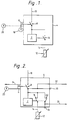
- an electronic earth leakage current breaker (ELCB) 2 that is capable of withstanding a maximum temperature of 45°C under load conditions, is mounted inside an enclosure 4.
- a temperature sensor 6 is mounted on the outside of the enclosure 5 and is electrically connected to the ELCB 2 via a switch 8.
- a power cable 10 enters the enclosure 4 and is connected to the switch 8.
- a self-regulating heater cable 12 has its power supply cable 14 extending into the enclosure 4 and connected to the ELCB 2 and to the switch 8 by a further switch 16.
- the ELCB In the event of an electrical fault that gives rise to a current flow through the ELCB 2 in excess of its trip value or 10mA, the ELCB operates to open the switch 16 thus cutting off the power supply to the heater 12.
- the temperature sensor 6 In the event of the temperature sensor 6 detecting an ambient temperature in excess of its trip value of 45°C, it is arranged to operate the switch 8 thus cutting off the power supply to the heater 12 and also to the ELCB 2 so that the latter component is not under load above its maximum operating temperature.
- the temperature sensor 6 may have a control arrangement 18 associated therewith in order that its critical ambient or trip temperature may be set at a predetermined value anywhere within the range 20°C to 45°C.
- the control arrangement 18 may be mounted alongside the sensor 6 on the enclosure 4 and operated manually, or it may be located remote therefrom as shown at 20, with a cable connection thereto, and operated manually or preferably by a computer.
- the electronic control and protection device of Figure 2 includes all the components of Figure 1, which for convenience have been given the same reference numerals, and some additional components.
- a switch 22 is connected in parallel with the switch 16 so as to be operated simultaneously therewith by the ELCB 2.
- An indicator lamp 24 in series with the switch 22 is mounted on the outside of the enclosure 4, and a cable 26 extends from the lamp 24 to remote equipment which may be an indicating and/or control equipment.
- remote equipment which may be an indicating and/or control equipment.
- a further indicator lamp 30 is mounted on the outside of the enclosure 4 and electrically connected to the switch 8 in order to indicate locally whether or not electrical power is supplied to the ELCB 2 and heater 12.
- a cable 32 also conveys this information to remote indicating equipment.
- a cable 34 extends also from the temperature sensor 6 to remote equipment for indicating the actual ambient temperature, and/or the fact that the critical temperature has been reached or exceeded.
- the various pieces of remote equipment referred to above may be separate, or may be combined together, giving information on the status of the various components of the protection and control device, indicating a fault or alarm condition, or exercising a control function as appropriate.
- a protection and control device may include selected ones only of the components and features described herein.
- a device described above with reference to Figure 1 or Figure 2 is used in facade heating of a building.
- the electronic control and protection device is made small enough to be located within the framework, which is of good thermally conductive material such as metal, surrounding a window or a door of a building that is subject to large heat loss, for example through glass panels.
- the heating to counteract the cold effect felt by a person in the vicinity of a large glass panel of a heated building, may conveniently be achieved by one or more self-regulating heaters, for example polymeric PTC (positive temperature coefficient) heaters as sold by Raychem under the tradenames CHEMELEX and AUTOTRACE, also mounted within the framework.
- the temperature sensor will arrange for current through the ELCB 2 to be interrupted and so maintain the integrity cf the electronic ELCB.
Landscapes
- Electrophonic Musical Instruments (AREA)
- Central Heating Systems (AREA)
- Emergency Protection Circuit Devices (AREA)
- Building Environments (AREA)
- Soundproofing, Sound Blocking, And Sound Damping (AREA)
- Air Bags (AREA)
Abstract
Description
- This invention relates to a facade of a building having a thermally conductive framework having a heating element connected to electrical power via an electronic control and protection device.
- Heated window and door surrounds are described in GB-A-2 096 221.
- Earth leakage current breakers (ELCBs) are known for plugging in between a source of electrical power and electric equipment to ensure the safety of an operator of the equipment under faulty or other conditions that could otherwise give rise to flow of a dangerously high earth current, of greater than about 10mA, through the operator. Traditionally, ELCBs are heavy, rugged pieces of equipment containing a lot of metal that can generally withstand high ambient temperatures under normal load conditions. GB Patent No. 1 208 208 discloses an earth-leakage transformer having a positive temperature coefficient resistor that responds to the heat generated in the coils of the transformer under conditions of sustained overload to operate a trip coil. Known electronic ELCBs however are limited to operating under normal conditions in maximum ambient temperatures of about 45 °C when power is being supplied through them to the associated equipment. US-A-3 803 455 describes an ELCB having a thermal override to open the circuit breaker. However, applications exist in which the temperature can reach 60°C to 70°C under normal load conditions either due to the electrical poser supplied or due to heating from another source e.g. the sun. For example a self-regulating electric heater, that is to say one having a positive temperature coefficient of resistance, mounted inside the metal facade surrounding a window can reach 60°C in the winter. In these circumstances, it may not be convenient to locate the electronic ELCB physically near the heater since it would have to be switched off. On the other hand, the traditional ELCBs are electromechanical devices and consequently too bulky for applications such as facade heating.
- Elongate heating elements, including those of the self-regulating type, are not always installed by electrically skilled personnel, so that extra safety must be ensured in the products as sold by the manufacturer.
- One object of the present invention is to provide a facade in which the electronic control and protection device is protected even during normal, i.e. non-overload, operating conditions, against excessive ambient temperatures.
- According to the present invention, there is provided a facade of a building, the facade comprising:
a thermally conductive framework having a channel therein, and
an elongate electrical heater which can be connected to electrical power and which is mounted on the facade to apply heat thereto;
characterised by:
an electronic protection device that is electrically connected between the heater and the power source and which, when the heater is connected to the power source, disconnects the heater from the power source when there is a leakage current from the heater to ground which increases to above a predetermined value;
switching means located between the protection device and the power source;
an enclosure within which the protection device is mounted, said enclosure being disposed within the channel of said framework; and
a temperature-sensing device which is mounted externally of the enclosure for sensing the ambient temperature of the facade framework, and which, when the heater is connected to the power source, disconnects the protection device and the heater from the power source when the ambient temperature of the facade increases to above a predetermined value within the range of 20° to 45°C. - The power interruption means, and electronic ELCB employing semiconductor chips, needs to be protected against an ambient temperature is excess of about 45°C when under load. By appropriate selection of components, in particular the semiconductor chips, the critical ambient temperature may in fact be greater than 45°C. Accordingly, the temperature sensing device, for example a thermostat, is arranged to switch the ELCB off when such predetermined temperature is exceeded. Switching off the ELCB also switches off the heater and the electronic ELCB will no longer be under load conditions and is thus able to withstand exposure to a much higher ambient temperature, say up to 80°C or even 100°C.
- The predetermined activating temperature may be variably selected either manually at the device itself or remotely. Remote control may be connected via a computer, so that, for example, the amount of heating provided at different parts of a building can be variably controlled as required.
- Advantageously the electrical heater is an elongate heating cable exhibiting a positive temperature coefficient (PTC) of resistivity, and is thus self-regulating. Such a heater is available from Raychem under the trade names CHEMELEX, AUTOTRACE and WINTERGARD.
- The electrical power and cable are connected to the ELCB within the enclosure for reasons of safety, and also to protect the ELCB device and its connections. The materials used for the enclosure are preferably substantially unaffected by any adverse environment to which they may be exposed, such as moisture condensation, salts and other ionic contaminants such as are found in industrial and coastal locations for example.
- Further installation and operational safety and convenience are provided by arranging for any cable, power or heater, extending from the control and protection device to have its free end terminated. That is to say, the free end of the cable will be completely sealed off, such as the termination of a PTC heater cable, or have a connector or plug fitted thereto.
- In one application of the present invention, a pre-terminated power supply cable is connected to the control and protection device within a compact enclosure of cross-section 15 x 15mm and length 120mm. a WINTERGARD PTC heater cable from Raychem is also connected to the ELCB device within the enclosure and extends therefrom through aluminium extruded profiles of a facade heating construction. Alternatively, the heater cable may be located remote from the enclosure and connected to the device therein by means of a further power cable lead.
- Some embodiments of electronic control and protection devices, each used in a facade in accordance with the present invention, will now be described, by way of example, with reference to the accompanying drawings, in which:-
- Figure 1
- shows schematically a basic version of the device and indicates some preferred optional features; and
- Figure 2
- shows schematically a more complex version of the device.
- Referring to Figure 1, an electronic earth leakage current breaker (ELCB) 2 that is capable of withstanding a maximum temperature of 45°C under load conditions, is mounted inside an
enclosure 4. Atemperature sensor 6 is mounted on the outside of the enclosure 5 and is electrically connected to theELCB 2 via aswitch 8. Apower cable 10 enters theenclosure 4 and is connected to theswitch 8. A self-regulatingheater cable 12 has itspower supply cable 14 extending into theenclosure 4 and connected to theELCB 2 and to theswitch 8 by afurther switch 16. - In the event of an electrical fault that gives rise to a current flow through the
ELCB 2 in excess of its trip value or 10mA, the ELCB operates to open theswitch 16 thus cutting off the power supply to theheater 12. - In the event of the
temperature sensor 6 detecting an ambient temperature in excess of its trip value of 45°C, it is arranged to operate theswitch 8 thus cutting off the power supply to theheater 12 and also to theELCB 2 so that the latter component is not under load above its maximum operating temperature. - As an optional feature, the
temperature sensor 6 may have a control arrangement 18 associated therewith in order that its critical ambient or trip temperature may be set at a predetermined value anywhere within therange 20°C to 45°C. The control arrangement 18 may be mounted alongside thesensor 6 on theenclosure 4 and operated manually, or it may be located remote therefrom as shown at 20, with a cable connection thereto, and operated manually or preferably by a computer. - The electronic control and protection device of Figure 2 includes all the components of Figure 1, which for convenience have been given the same reference numerals, and some additional components.
- Referring to Figure 2, a
switch 22 is connected in parallel with theswitch 16 so as to be operated simultaneously therewith by theELCB 2. Anindicator lamp 24 in series with theswitch 22 is mounted on the outside of theenclosure 4, and acable 26 extends from thelamp 24 to remote equipment which may be an indicating and/or control equipment. When theELCB 2 opens theswitch 16, as described with reference to Figure 1, theswitch 22 is also opened and the normally onlamp 24 is extinguished, and this is detected and indicated in an appropriate manner by remote alarm indicating equipment. The existence of an electrical fault is thus indicated locally on theenclosure 4 of the device itself and also remotely. - A
further indicator lamp 30 is mounted on the outside of theenclosure 4 and electrically connected to theswitch 8 in order to indicate locally whether or not electrical power is supplied to theELCB 2 andheater 12. Acable 32 also conveys this information to remote indicating equipment. - A
cable 34 extends also from thetemperature sensor 6 to remote equipment for indicating the actual ambient temperature, and/or the fact that the critical temperature has been reached or exceeded. - The various pieces of remote equipment referred to above may be separate, or may be combined together, giving information on the status of the various components of the protection and control device, indicating a fault or alarm condition, or exercising a control function as appropriate.
- It is to be understood that a protection and control device may include selected ones only of the components and features described herein.
- A device described above with reference to Figure 1 or Figure 2 is used in facade heating of a building. Thus, the electronic control and protection device is made small enough to be located within the framework, which is of good thermally conductive material such as metal, surrounding a window or a door of a building that is subject to large heat loss, for example through glass panels. The heating, to counteract the cold effect felt by a person in the vicinity of a large glass panel of a heated building, may conveniently be achieved by one or more self-regulating heaters, for example polymeric PTC (positive temperature coefficient) heaters as sold by Raychem under the tradenames CHEMELEX and AUTOTRACE, also mounted within the framework. In such an arrangement, when the ambient temperature of the facade exceeds a predetermined value the temperature sensor will arrange for current through the
ELCB 2 to be interrupted and so maintain the integrity cf the electronic ELCB.
Claims (6)
- A facade of a building, the facade comprising:
a thermally conductive framework having a channel therein, and
an elongate electrical heater (12) which can be connected to electrical power and which is mounted on the facade to apply heat thereto;
characterised by:
an electronic protection device (2) that is electrically connected between the heater (12) and the power source (10) and which, when the heater (12) is connected to the power source, disconnects the heater (12) from the power source (10) when there is a leakage current from the heater to ground which increases to above a predetermined value;
switching means (8) located between the protection device (2) and the power source;
an enclosure (4) within which the protection device (2) is mounted, said enclosure (4) being disposed within the channel of said framework; and
a temperature-sensing device (6) which is mounted externally of the enclosure (4) for sensing the ambient temperature of the facade framework, and which, when the heater (12) is connected to the power source (10), disconnects the protection device (2) and the heater (12) from the power source when the ambient temperature of the facade increases to above a predetermined value within the range of 20° to 45°C. - A facade according to claim 1, wherein said predetermined ambient temperature value can be changed.
- A facade according to claim 1 or claim 2, including indicating equipment (24) which is located remote from the protection device (4) and which indicates when the protection device (4) has been disconnected from the power source (10).
- A facade according to any one of claims 1 to 3, including indicating equipment which indicates when said predetermined value of ambient temperature has been exceeded.
- A facade as claimed in any one of claims 1 to 4 wherein the elongate heater is a self-regulating heater cable.
- A facade as claimed in claim 5 wherein the heater cable is a polymeric heater cable capable of exhibiting a positive temperature coefficient of resistance.
Applications Claiming Priority (3)
| Application Number | Priority Date | Filing Date | Title |
|---|---|---|---|
| GB8810938 | 1988-05-09 | ||
| GB888810938A GB8810938D0 (en) | 1988-05-09 | 1988-05-09 | Electronic control & protection device |
| PCT/GB1989/000503 WO1989011174A1 (en) | 1988-05-09 | 1989-05-09 | Electronic control and protection device |
Publications (2)
| Publication Number | Publication Date |
|---|---|
| EP0449822A1 EP0449822A1 (en) | 1991-10-09 |
| EP0449822B1 true EP0449822B1 (en) | 1994-09-21 |
Family
ID=10636582
Family Applications (1)
| Application Number | Title | Priority Date | Filing Date |
|---|---|---|---|
| EP89905438A Expired - Lifetime EP0449822B1 (en) | 1988-05-09 | 1989-05-09 | Electronic control and protection device |
Country Status (7)
| Country | Link |
|---|---|
| EP (1) | EP0449822B1 (en) |
| JP (1) | JPH03504314A (en) |
| AT (1) | ATE112111T1 (en) |
| DE (1) | DE68918461T2 (en) |
| DK (1) | DK268190A (en) |
| GB (1) | GB8810938D0 (en) |
| WO (1) | WO1989011174A1 (en) |
Families Citing this family (2)
| Publication number | Priority date | Publication date | Assignee | Title |
|---|---|---|---|---|
| DE102014118530A1 (en) | 2014-12-12 | 2016-06-16 | Bernhard Synoracki | Warming facade jacket |
| DE102024106565A1 (en) * | 2024-03-07 | 2025-09-11 | Burkhard Herbach | Control device for an electric surface heating and surface heating |
Family Cites Families (6)
| Publication number | Priority date | Publication date | Assignee | Title |
|---|---|---|---|---|
| AT285709B (en) * | 1967-12-19 | 1970-11-10 | Uninorm Anstalt | Residual current circuit breaker with additional overcurrent release |
| DE2221055A1 (en) * | 1972-04-28 | 1973-11-08 | Glaverbel | HEATABLE GLAZING ELEMENT |
| US3803455A (en) * | 1973-01-02 | 1974-04-09 | Gen Electric | Electric circuit breaker static trip unit with thermal override |
| DE2425081A1 (en) * | 1974-05-24 | 1975-12-11 | Bbc Brown Boveri & Cie | Protection system for electric cookers - has main switch disconnecting all supply poles on short ccts. and rising temp. |
| US4359626A (en) * | 1980-03-18 | 1982-11-16 | Potter Bronson M | Electric blanket heating control with capacitance sensing |
| GB2096221A (en) * | 1981-04-07 | 1982-10-13 | Rea John Terence | Anti-condensation device |
-
1988
- 1988-05-09 GB GB888810938A patent/GB8810938D0/en active Pending
-
1989
- 1989-05-09 WO PCT/GB1989/000503 patent/WO1989011174A1/en not_active Ceased
- 1989-05-09 JP JP1505596A patent/JPH03504314A/en active Pending
- 1989-05-09 EP EP89905438A patent/EP0449822B1/en not_active Expired - Lifetime
- 1989-05-09 DE DE68918461T patent/DE68918461T2/en not_active Expired - Fee Related
- 1989-05-09 AT AT89905438T patent/ATE112111T1/en not_active IP Right Cessation
-
1990
- 1990-11-08 DK DK268190A patent/DK268190A/en not_active Application Discontinuation
Also Published As
| Publication number | Publication date |
|---|---|
| EP0449822A1 (en) | 1991-10-09 |
| ATE112111T1 (en) | 1994-10-15 |
| DK268190D0 (en) | 1990-11-08 |
| JPH03504314A (en) | 1991-09-19 |
| GB8810938D0 (en) | 1988-06-15 |
| WO1989011174A1 (en) | 1989-11-16 |
| DE68918461D1 (en) | 1994-10-27 |
| DK268190A (en) | 1990-11-08 |
| DE68918461T2 (en) | 1995-05-18 |
Similar Documents
| Publication | Publication Date | Title |
|---|---|---|
| US5710408A (en) | Automatic controlled for an ice and snow melting system with ground fault circuit interruption | |
| FI82997B (en) | KRETSAVBRYTARE. | |
| US6639502B2 (en) | Overload protector with control element | |
| US5541803A (en) | Electrical safety device | |
| US4205223A (en) | Heating circuits for detection of localized overheating | |
| EP0352987B1 (en) | Solid state circuit protector | |
| US4278874A (en) | Heating circuits | |
| US6172647B1 (en) | Remote control for use with a deicing apparatus | |
| PL191284B1 (en) | Method for switching off a power supply in a dangerous situation and a corresponding safeguarding arrangement | |
| US6104352A (en) | Remote testing and monitoring apparatus for use with antenna reflector deicing systems | |
| US7164102B2 (en) | Self heating thermal protector | |
| KR100713224B1 (en) | Power Distribution Device with Optimal Operation Environment Control | |
| EP0449822B1 (en) | Electronic control and protection device | |
| JPH079782B2 (en) | Circuit breaker with overheat prevention device | |
| US6839212B2 (en) | Bus bar thermal detection | |
| CN1068993C (en) | Electric motor with means for preventing thermal overload | |
| JP2016195016A (en) | Terminal connection failure detector | |
| JP6924502B2 (en) | Terminal connection failure detector | |
| AU5771996A (en) | Electric power distribution unit for buildings | |
| GB2028607A (en) | Heating circuits | |
| WO2001048498A1 (en) | ELECTRICAL FLASHOVER MONITOR-E FOM?x+¿ | |
| SU995071A1 (en) | Room electric heating device | |
| CA1220262A (en) | Electronic safety and heat control means | |
| KR200276698Y1 (en) | Circuit breaker using positive temperature coefficent thermister | |
| Baen | Advancements in heat tracing controls to meet code and reduce energy consumption |
Legal Events
| Date | Code | Title | Description |
|---|---|---|---|
| PUAI | Public reference made under article 153(3) epc to a published international application that has entered the european phase |
Free format text: ORIGINAL CODE: 0009012 |
|
| 17P | Request for examination filed |
Effective date: 19901107 |
|
| AK | Designated contracting states |
Kind code of ref document: A1 Designated state(s): AT BE CH DE FR GB IT LI NL SE |
|
| 17Q | First examination report despatched |
Effective date: 19930301 |
|
| GRAA | (expected) grant |
Free format text: ORIGINAL CODE: 0009210 |
|
| AK | Designated contracting states |
Kind code of ref document: B1 Designated state(s): AT BE CH DE FR GB IT LI NL SE |
|
| PG25 | Lapsed in a contracting state [announced via postgrant information from national office to epo] |
Ref country code: IT Free format text: LAPSE BECAUSE OF FAILURE TO SUBMIT A TRANSLATION OF THE DESCRIPTION OR TO PAY THE FEE WITHIN THE PRE;WARNING: LAPSES OF ITALIAN PATENTS WITH EFFECTIVE DATE BEFORE 2007 MAY HAVE OCCURRED AT ANY TIME BEFORE 2007. THE CORRECT EFFECTIVE DATE MAY BE DIFFERENT FROM THE ONE RECORDED.SCRIBED TIME-LIMIT Effective date: 19940921 Ref country code: BE Effective date: 19940921 Ref country code: CH Effective date: 19940921 Ref country code: LI Effective date: 19940921 Ref country code: AT Effective date: 19940921 Ref country code: NL Effective date: 19940921 |
|
| REF | Corresponds to: |
Ref document number: 112111 Country of ref document: AT Date of ref document: 19941015 Kind code of ref document: T |
|
| REF | Corresponds to: |
Ref document number: 68918461 Country of ref document: DE Date of ref document: 19941027 |
|
| ET | Fr: translation filed | ||
| PG25 | Lapsed in a contracting state [announced via postgrant information from national office to epo] |
Ref country code: SE Effective date: 19941221 |
|
| REG | Reference to a national code |
Ref country code: CH Ref legal event code: PL |
|
| NLV1 | Nl: lapsed or annulled due to failure to fulfill the requirements of art. 29p and 29m of the patents act | ||
| PGFP | Annual fee paid to national office [announced via postgrant information from national office to epo] |
Ref country code: GB Payment date: 19950428 Year of fee payment: 7 |
|
| PGFP | Annual fee paid to national office [announced via postgrant information from national office to epo] |
Ref country code: FR Payment date: 19950510 Year of fee payment: 7 |
|
| PLBE | No opposition filed within time limit |
Free format text: ORIGINAL CODE: 0009261 |
|
| STAA | Information on the status of an ep patent application or granted ep patent |
Free format text: STATUS: NO OPPOSITION FILED WITHIN TIME LIMIT |
|
| 26N | No opposition filed | ||
| PG25 | Lapsed in a contracting state [announced via postgrant information from national office to epo] |
Ref country code: GB Effective date: 19960509 |
|
| GBPC | Gb: european patent ceased through non-payment of renewal fee |
Effective date: 19960509 |
|
| PG25 | Lapsed in a contracting state [announced via postgrant information from national office to epo] |
Ref country code: FR Effective date: 19970131 |
|
| REG | Reference to a national code |
Ref country code: FR Ref legal event code: ST |
|
| PGFP | Annual fee paid to national office [announced via postgrant information from national office to epo] |
Ref country code: DE Payment date: 20010430 Year of fee payment: 13 |
|
| PG25 | Lapsed in a contracting state [announced via postgrant information from national office to epo] |
Ref country code: DE Free format text: LAPSE BECAUSE OF NON-PAYMENT OF DUE FEES Effective date: 20021203 |