EP0449692B1 - Modulare Pumpe mit mehreren Auslässen, jeder versorgt durch eine Pumpeinheit - Google Patents
Modulare Pumpe mit mehreren Auslässen, jeder versorgt durch eine Pumpeinheit Download PDFInfo
- Publication number
- EP0449692B1 EP0449692B1 EP91400680A EP91400680A EP0449692B1 EP 0449692 B1 EP0449692 B1 EP 0449692B1 EP 91400680 A EP91400680 A EP 91400680A EP 91400680 A EP91400680 A EP 91400680A EP 0449692 B1 EP0449692 B1 EP 0449692B1
- Authority
- EP
- European Patent Office
- Prior art keywords
- pump
- cartridges
- fact
- pump body
- pistons
- Prior art date
- Legal status (The legal status is an assumption and is not a legal conclusion. Google has not performed a legal analysis and makes no representation as to the accuracy of the status listed.)
- Expired - Lifetime
Links
- 238000005086 pumping Methods 0.000 claims abstract description 31
- 125000006850 spacer group Chemical group 0.000 claims 2
- 230000000295 complement effect Effects 0.000 claims 1
- 230000008878 coupling Effects 0.000 claims 1
- 238000010168 coupling process Methods 0.000 claims 1
- 238000005859 coupling reaction Methods 0.000 claims 1
- 210000002445 nipple Anatomy 0.000 claims 1
- 239000000314 lubricant Substances 0.000 abstract description 3
- 239000007788 liquid Substances 0.000 description 8
- 230000000694 effects Effects 0.000 description 2
- 230000004048 modification Effects 0.000 description 2
- 238000012986 modification Methods 0.000 description 2
- 229910045601 alloy Inorganic materials 0.000 description 1
- 239000000956 alloy Substances 0.000 description 1
- 238000005266 casting Methods 0.000 description 1
- 238000004140 cleaning Methods 0.000 description 1
- 238000002485 combustion reaction Methods 0.000 description 1
- 239000012530 fluid Substances 0.000 description 1
- 239000000446 fuel Substances 0.000 description 1
- 238000004519 manufacturing process Methods 0.000 description 1
- 239000000463 material Substances 0.000 description 1
- 238000000034 method Methods 0.000 description 1
- 238000010926 purge Methods 0.000 description 1
- 238000007789 sealing Methods 0.000 description 1
Images
Classifications
-
- F—MECHANICAL ENGINEERING; LIGHTING; HEATING; WEAPONS; BLASTING
- F16—ENGINEERING ELEMENTS AND UNITS; GENERAL MEASURES FOR PRODUCING AND MAINTAINING EFFECTIVE FUNCTIONING OF MACHINES OR INSTALLATIONS; THERMAL INSULATION IN GENERAL
- F16N—LUBRICATING
- F16N13/00—Lubricating-pumps
- F16N13/22—Lubricating-pumps with distributing equipment
-
- F—MECHANICAL ENGINEERING; LIGHTING; HEATING; WEAPONS; BLASTING
- F04—POSITIVE - DISPLACEMENT MACHINES FOR LIQUIDS; PUMPS FOR LIQUIDS OR ELASTIC FLUIDS
- F04B—POSITIVE-DISPLACEMENT MACHINES FOR LIQUIDS; PUMPS
- F04B1/00—Multi-cylinder machines or pumps characterised by number or arrangement of cylinders
-
- F—MECHANICAL ENGINEERING; LIGHTING; HEATING; WEAPONS; BLASTING
- F16—ENGINEERING ELEMENTS AND UNITS; GENERAL MEASURES FOR PRODUCING AND MAINTAINING EFFECTIVE FUNCTIONING OF MACHINES OR INSTALLATIONS; THERMAL INSULATION IN GENERAL
- F16N—LUBRICATING
- F16N13/00—Lubricating-pumps
- F16N13/02—Lubricating-pumps with reciprocating piston
- F16N13/06—Actuation of lubricating-pumps
Definitions
- the present invention relates to a modular pump with several pumping elements actuated by a common external control, and with several outputs each supplied by one of said pumping elements.
- the pump body contains a predetermined number of pumping elements each formed by a cylinder formed in the form of a bore of predetermined diameter in the pump body, and a piston of predetermined stroke mounted in said cylinder. Consequently, each pump has a number of starts or exits predetermined by the number of cylinders, and each pumping element has a capacity predetermined by the diameter and the stroke of the piston mounted in the pump body.
- Such a pump structure has the disadvantage that if it is desired to modify the number of pump outlets and / or the capacity of each pumping element, it is necessary to machine the pump body as a function of these characteristics.
- US-A-2,160,978 discloses a fuel supply pump for an internal combustion engine.
- the pump comprises several pumping elements in the form of cartridges mounted in parallel bores of a support disc which is fixed in the pump casing. Each cartridge is axially traversed by a bore forming a cylinder to receive a piston.
- This document which proposes a modular pump with removable pumping elements, also does not provide the possibility of modifying the operating characteristics of the pump to adapt them to the conditions of use of the pump.
- the present invention aims to remedy these drawbacks by a modular pump designed so that from a single pump body, it is possible to produce pumps with a variable number of outlets and a variable capacity of each element. pumping.
- Another object of the invention is to produce a modular pump designed so as to simplify the disassembly of the pumping elements and the reassembly of the pumping elements, possibly after their exchange against pumping elements of the same capacity or of different capacity.
- the object of the invention is to produce a modular pump, the pump body of which can be manufactured using simple methods and from inexpensive materials.
- the modular pump according to the invention comprises several pumping elements each comprising a piston sliding in a cylinder inside a common pump body.
- the pistons are actuated in the pumping direction by a common external control, against the action of return springs.
- the pump has several outputs each supplied by one of said pumping elements.
- each pumping element comprises a cartridge axially traversed by a bore forming a cylinder receiving a piston, said cartridges being able to have cylinders and pistons of different diameters.
- the pump body has several parallel bores which can receive either said cartridges or full cartridges without cylinder and without piston.
- the cartridges are held in the bores of the pump body by a cover attached to the pump body opposite the external control and delimiting with the pump body a supply chamber communicating with a tank under load and with the cartridge cylinders.
- each cartridge is preferably subdivided, in the axial direction, into a piston guide section turned towards the external control and into a cylinder section turned towards the cover.
- Each cartridge is mounted in a bore of the pump body by its part corresponding to said guide section and is provided with connecting means making said supply chamber communicate with its bore between said two sections.
- the pistons are mounted in the cartridges so as to disengage said connection means and said cylinder sections under the action of the return springs when they are not actuated by the external control.
- the pistons can advantageously be returned to the external control by springs bearing on the cartridges.
- the pistons are actuated by the external control by means of a common plate with a centering tip guided in the pump body.
- a shim exchangeable for a shim of different height is placed between said plate actuating the pistons and the fixed-stroke output member of the external control.
- the cartridges have a check valve at their end facing the outlets.
- the outlet orifices can be made in the cover in alignment with the cartridges, the return springs of the check valves bearing against the outlet fittings screwed into said orifices.
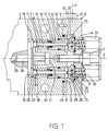
- the pump illustrated in the drawings comprises a pump body 1 on one end of which is fixed an electromagnet 2 by screws, not shown.
- each stepped bore 3 receives a pumping cartridge 5 held in its bore 3 by a cover 6 fixed to the pump body 1 on the end opposite to the electromagnet 2.
- the cover 6 is fixed to the pump body 1 using a central screw 7, the centering and the correct positioning of the cover 6 relative to the pump body 1 being ensured by a centering tip. 8 annular of the pump body 1 and by a centering foot 9.
- the cover 6 defines with the pump body 1 a chamber 10 which is supplied with fluid to be distributed from a reservoir in load not shown connected to an orifice 11 formed in the cover 6, orifice of which only the axis is shown.
- the chamber 10 can be purged by means of a purge plug 12.
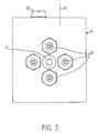
- the cover 6 also comprises four outlet connections 13 screwed into four outlet orifice 14 formed in the cover 6 in alignment with the bores 3 of the pump body 1.
- Each pumping cartridge 5 is traversed over its entire length by an axial bore 15 in which is slidably mounted a piston 16 biased towards the control electromagnet 2 by a return spring 17 which bears on the cartridge 5 and on a head 18 that the piston 16 has at its end facing the control electromagnet 2.
- the heads 18 of all the pistons 16 are applied against a plate 19 mounted axially movable in the pump body 1 while being centered in the latter by a centering nozzle 20 sliding in an axial blind hole 21 of the pump body 1.
- the centering nozzle 20 has a polygonal profile and that the hole 21 is cylindrical, which prevents the nozzle from acting like a piston in the hole.
- the body of the cartridge 5 is subdivided into a section 22 for guiding the piston 16 and into a pumping section 23 which contains the bore or pumping cylinder proper.
- Transversal holes 24 formed in the body of the cartridge 5 between said two sections 22, 23 allow the pumping cylinder 25 of section 23 to communicate with the chamber 10 when the piston 16 is returned to the rest position by its spring 17.
- the bore 15 has the same diameter in the section 22 for guiding the piston 16 and in the pumping section 23 corresponding to the pumping cylinder 25.
- each cartridge 5 receives a non-return valve 26 comprising a seal carrier body 27 slidably mounted in an enlarged section 28 of the bore 15 of the cartridge body 5, at the end facing the cover 6.
- the seal carrier body 27 carries a seal 29 by which it is applied against the bottom of the enlarged section 28 of the bore 15 under the action of a return spring 30 bearing on the outlet connector 13. It should be noted that the seal-carrying body 27 is extended towards the outlet by a nozzle 31 which somewhat exceeds the outside face of the cover 6.
- a seal 32 is provided between each cartridge 5 and the bore 3 of the pump body 1 receiving this cartridge. Furthermore, a seal 33 is provided between each cartridge 5 and the piston 16 sliding in the latter. A seal 34 is also provided between each cartridge 5 and the cover 6. Finally, a seal 35 is provided between the centering nozzle 8 of the pump body 1 and the cover 6.
- a drainage orifice 36 is also provided in the pump body 1, this orifice 36 communicating with the chamber 37 provided between the pump body 1 and the control electromagnet 2 to receive the plate 19.
- This drainage orifice 36 makes it possible to evacuate the slight leaks of liquid which could occur in the long run between the cartridges 5 and the pistons 16 sliding in the latter.
- a shim 39 is provided, the function of which will appear subsequently.
- the pump body 1 includes fixing holes 40 intended for the screw fixing of the pump assembly on a support not shown.
- the plate 19 When the electromagnet 2 is energized, the plate 19 is actuated to the right in FIG. 1 by the pusher 37 and the wedge 38 and pushes the pistons 16 into the cylinders 25.
- the liquid contained in the cylinders 25 is thus compressed and, after lifting the valves 26 from their seats, expelled towards the outlet until the pistons 16 have reached the end of their travel.
- each piston 16 sends a corresponding volume of liquid through the corresponding outlet connector 13 which is a function of the stroke and the diameter of the piston 16.
- the pump body 1 and the cover 6 can be produced for example by pressure casting from alloys having no particular characteristics of resistance to friction. This reduces the cost of the pump body and the cover.
- the friction which can occur between the centering end piece 20 of the plate 19 and the pump body 1 is low, but it is possible to design a lining for the hole 21 in the pump body 1 if necessary.
- the end pieces 31 provided on the seal-carrying body 27 of the valves 26 allow, after unscrewing the outlet fittings 13, to easily remove the valves 26, for example for cleaning purposes, without having to dismantle the cover 6.
- the pump according to the invention can preferably be used for the sequential dispensing of liquid or viscous lubricant, in particular of volumes from 5 to 50 mm3 at each sequence by each outlet.
- the control electromagnet 2 could be replaced, for example, by a pneumatically or hydraulically actuated cylinder.
Landscapes
- Engineering & Computer Science (AREA)
- General Engineering & Computer Science (AREA)
- Mechanical Engineering (AREA)
- Reciprocating Pumps (AREA)
- Details Of Reciprocating Pumps (AREA)
- External Artificial Organs (AREA)
- Massaging Devices (AREA)
- Compressors, Vaccum Pumps And Other Relevant Systems (AREA)
- Devices For Dispensing Beverages (AREA)
Claims (9)
- Modular aufgebaute Pumpe mit mehreren Pumpelementen, von denen jedes einen in einem Zylinder (15, 25) im Inneren eines gemeinsamen Pumpenkörpers (1) verschiebbaren Kolben (16) aufweist, wobei die Kolben durch einen gemeinsamen äußeren Antrieb (2) entgegen der Wirkung von Rückstellfedern (17) im Pumpsinne angetrieben sind, wobei die Pumpe mehrere Auslässe (13) aufweist, von denen jeder durch eines der Pumpelemente gespeist wird, wobei jedes Pumpelement einen Einsatz (5) aufweist, der in axialer Richtung von einer Bohrung (15, 25) durchsetzt ist, die einen einen Kolben (16) aufnehmenden Zylinder bildet, wobei der Pumpenkörper (1) mehrere gleiche, parallele Bohrungen (3) aufweist, um die Einsätze aufzunehmen, dadurch gekennzeichnet, daß die Einsätze Zylinder und Kolben mit unterschiedlichen Durchmessern aufweisen können und daß die Bohrungen (3) des Pumpenkörpers wahlweise die vorgenannten Einsätze (5) oder Blindeinsätze ohne Zylinder und ohne Kolben aufnehmen.
- Pumpe nach Anspruch 1, dadurch gekennzeichnet, daß die Einsätze (5) in den Bohrungen (3) des Pumpenkörpers (1) durch einen an dem Pumpenkörper dem gemeinsamen Antrieb (2) gegenüberliegend angebrachten Deckel (6) gehalten sind, der zusammen mit dem Pumpenkörper eine Kammer (10) begrenzt, die mit einem befüllten Behälter und mit den Zylindern (25) der Einsätze in Verbindung steht.
- Pumpe nach Anspruch 2, dadurch gekennzeichnet, daß die Bohrung der Einsätze in axialer Richtung in einen dem Antrieb (2) zugewandten Kolbenführungsabschnitt (15) und einen dem Deckel (6) zugewandten Zylinderabschnitt (25) unterteilt ist, daß die Einsätze in den Bohrungen (3) des Pumpenkörpers durch die den Führungsabschnitten entsprechenden Teile befestigt sind und mit Zuleitungsmitteln (24) versehen sind, die die Kammer (10) mit der Bohrung der Einsätze zwischen den zwei Abschnitten in Verbindung setzen, und daß die Kolben (16) in den Einsätzen (5) derart angeordnet sind, daß sie die Zuleitungsmittel (24) und die vorgenannten Zylinderabschnitte (25) unter der Einwirkung der Rückstellfedern (17) freigeben, wenn sie von dem Antrieb (2) nicht betätigt sind.
- Pumpe nach einem der vorstehenden Ansprüche, dadurch gekennzeichnet, daß die Kolben (16) von den sich auf den Einsätzen (5) abstützenden Federn (17) zu dem Antrieb (2) hin zurückgestellt werden.
- Pumpe nach einem der vorstehenden Ansprüche, dadurch gekennzeichnet, daß die Kolben (16) von dem Antrieb (2) mittels einer gemeinsamen Scheibe (19) angetrieben sind, die einen in dem Pumpenkörper (1) geführten Zentrieransatz (20) aufweist.
- Pumpe nach Anspruch 5, dadurch gekennzeichnet, daß zwischen dem Antrieb (2) und der Scheibe (19) ein gegen ein Distanzstück unterschiedlicher Länge auswechselbares Distanzstück (39) angeordnet ist.
- Pumpe nach einem der vorstehenden Ansprüche, dadurch gekennzeichnet, daß die Einsätze (5) an ihrem den Auslässen zugewandten Ende jeweils ein Rückschlagventil (26) enthalten.
- Pumpe nach Anspruch 7, dadurch gekennzeichnet, daß die Auslaßöffnungen (14) in dem Deckel (6) fluchtend mit den die Einsätze (5) aufnehmenden Bohrungen (3) angeordnet sind und daß sich die Rückstellfedern (30) der Rückschlagventile (26) auf den in die Auslaßöffnungen (14) eingeschraubten Auslaßanschlußteilen (13) abstützen.
- Pumpe nach einem der vorstehenden Ansprüche, dadurch gekennzeichnet, daß der Pumpenkörper (1) und der Deckel (6) komplementäre Mittel (8, 9) zur Zentrierung und Positionierung aufweisen.
Applications Claiming Priority (2)
| Application Number | Priority Date | Filing Date | Title |
|---|---|---|---|
| FR9003832 | 1990-03-26 | ||
| FR9003832A FR2660021B1 (fr) | 1990-03-26 | 1990-03-26 | Pompe modulaire a plusieurs sorties alimentees chacune par un element de pompage. |
Publications (2)
| Publication Number | Publication Date |
|---|---|
| EP0449692A1 EP0449692A1 (de) | 1991-10-02 |
| EP0449692B1 true EP0449692B1 (de) | 1995-01-25 |
Family
ID=9395111
Family Applications (1)
| Application Number | Title | Priority Date | Filing Date |
|---|---|---|---|
| EP91400680A Expired - Lifetime EP0449692B1 (de) | 1990-03-26 | 1991-03-13 | Modulare Pumpe mit mehreren Auslässen, jeder versorgt durch eine Pumpeinheit |
Country Status (5)
| Country | Link |
|---|---|
| EP (1) | EP0449692B1 (de) |
| AT (1) | ATE117786T1 (de) |
| DE (1) | DE69106916T2 (de) |
| ES (1) | ES2067169T3 (de) |
| FR (1) | FR2660021B1 (de) |
Families Citing this family (6)
| Publication number | Priority date | Publication date | Assignee | Title |
|---|---|---|---|---|
| GB9405028D0 (en) * | 1994-03-15 | 1994-04-27 | Counting Tech Ltd | Fluid diluter |
| AU2848999A (en) * | 1998-04-03 | 1999-10-25 | Allen Norman Geldenhuys | Multi-cylinder piston pump |
| DE202005018630U1 (de) | 2005-11-30 | 2006-03-09 | Lincoln Gmbh & Co. Kg | Förderpumpe und modulares Pumpensystem |
| DE102007011192A1 (de) * | 2007-03-06 | 2008-09-18 | Perma-Tec Gmbh & Co. Kg | Dosiervorrichtung für einen Schmierstoffspender |
| DE102019104648A1 (de) * | 2019-02-25 | 2020-08-27 | Thomas Magnete Gmbh | Pumpe mit einer Mehrzahl von Auslässen |
| WO2020180724A1 (en) * | 2019-03-01 | 2020-09-10 | Procept Biorobotics Corporation | Pump cartridge and console |
Family Cites Families (3)
| Publication number | Priority date | Publication date | Assignee | Title |
|---|---|---|---|---|
| US2160978A (en) * | 1935-12-17 | 1939-06-06 | Eclipse Aviat Corp | Fuel pump |
| US2739671A (en) * | 1953-02-12 | 1956-03-27 | Dewandre Co Ltd C | Lubricating devices |
| US4032263A (en) * | 1975-09-25 | 1977-06-28 | Lear Siegler, Inc. | Pump with coaxial inlet and outlet valve arrangement |
-
1990
- 1990-03-26 FR FR9003832A patent/FR2660021B1/fr not_active Expired - Fee Related
-
1991
- 1991-03-13 AT AT91400680T patent/ATE117786T1/de not_active IP Right Cessation
- 1991-03-13 ES ES91400680T patent/ES2067169T3/es not_active Expired - Lifetime
- 1991-03-13 DE DE69106916T patent/DE69106916T2/de not_active Expired - Fee Related
- 1991-03-13 EP EP91400680A patent/EP0449692B1/de not_active Expired - Lifetime
Also Published As
| Publication number | Publication date |
|---|---|
| FR2660021A1 (fr) | 1991-09-27 |
| FR2660021B1 (fr) | 1992-07-10 |
| DE69106916D1 (de) | 1995-03-09 |
| ATE117786T1 (de) | 1995-02-15 |
| DE69106916T2 (de) | 1995-09-21 |
| EP0449692A1 (de) | 1991-10-02 |
| ES2067169T3 (es) | 1995-03-16 |
Similar Documents
| Publication | Publication Date | Title |
|---|---|---|
| EP0117806B1 (de) | Flüssigkeitsverteiler, insbesondere für Fernsteuerung | |
| EP0280600B1 (de) | Hydraulischer Kettenspanner | |
| FR2492473A1 (fr) | Pompe a membrane a compensation dans la chambre hydraulique de commande | |
| EP0449692B1 (de) | Modulare Pumpe mit mehreren Auslässen, jeder versorgt durch eine Pumpeinheit | |
| EP0376815B1 (de) | Pumpe für kleine Mengen, insbesondere für die Schmierung einer Zweitaktbrennkraftmaschine | |
| FR2677429A1 (fr) | Dispositif pour un doseur de lubrifiant. | |
| FR2678330A1 (fr) | Dispositif pour arbre a cames comprenant au moins une came pouvant etre desactivee. | |
| FR2720120A3 (fr) | Pompe à huile à double commande manuelle/pneumatique. | |
| EP0428192B1 (de) | Stufenloses hydrostatisches Radialkolbengetriebe | |
| FR2780762A1 (fr) | Soupape anti-retour | |
| EP0180510B1 (de) | Hydraulische Kolbenpumpe mit zwangsläufig angetriebenen Einlassventilen | |
| FR2807804A1 (fr) | Dispositif d'actionnement pour un train d'entrainement | |
| WO2023187212A1 (fr) | Tête de connexion rapportable sur une ouverture d'un élément de tuyauterie à bride pour son contrôle sous pression | |
| EP3308057B1 (de) | Druckbegrenzungsvorrichtung, insbesondere für ein hydraulisches hilfssystem für fahrzeuge | |
| FR2749616A1 (fr) | Pompe a haute pression pour tous liquides | |
| CH640310A5 (en) | Hydraulic pump with a sprung valve | |
| FR2474319A1 (fr) | Dispositif d'injection sans aiguille de substances medicamenteuses liquides | |
| BE377216A (de) | ||
| FR2523655A1 (fr) | Pompe hydraulique a pistons axiaux commandes par un plateau biais, munis de moyens d'autoamorcage | |
| FR2735840A1 (fr) | Distributeur pneumatique a tiroir | |
| FR2667381A1 (fr) | Distributeur-doseur de lubrifiant pour installation de graissage centralise. | |
| FR2802985A1 (fr) | Verin a point d'arret intermediaire | |
| FR2993325A1 (fr) | Dispositif de commande du deplacement d'un verin hydraulique, notamment pour machines hydrauliques. | |
| EP0089296A1 (de) | Hydraulische Axialkolbenpumpe mit Schrägscheibe und einer Einrichtung zum Selbstansaugen | |
| FR2795455A1 (fr) | Module de commande, soumis a l'action d'une pression, presentant une fuite reduite, notamment pour injecteur de carburant |
Legal Events
| Date | Code | Title | Description |
|---|---|---|---|
| PUAI | Public reference made under article 153(3) epc to a published international application that has entered the european phase |
Free format text: ORIGINAL CODE: 0009012 |
|
| AK | Designated contracting states |
Kind code of ref document: A1 Designated state(s): AT BE CH DE DK ES FR GB GR IT LI LU NL SE |
|
| 17P | Request for examination filed |
Effective date: 19911011 |
|
| 17Q | First examination report despatched |
Effective date: 19930528 |
|
| GRAA | (expected) grant |
Free format text: ORIGINAL CODE: 0009210 |
|
| ITF | It: translation for a ep patent filed | ||
| AK | Designated contracting states |
Kind code of ref document: B1 Designated state(s): AT BE CH DE DK ES FR GB GR IT LI LU NL SE |
|
| PG25 | Lapsed in a contracting state [announced via postgrant information from national office to epo] |
Ref country code: NL Effective date: 19950125 Ref country code: GR Free format text: LAPSE BECAUSE OF FAILURE TO SUBMIT A TRANSLATION OF THE DESCRIPTION OR TO PAY THE FEE WITHIN THE PRESCRIBED TIME-LIMIT Effective date: 19950125 Ref country code: GB Effective date: 19950125 Ref country code: DK Effective date: 19950125 Ref country code: AT Effective date: 19950125 |
|
| REF | Corresponds to: |
Ref document number: 117786 Country of ref document: AT Date of ref document: 19950215 Kind code of ref document: T |
|
| REF | Corresponds to: |
Ref document number: 69106916 Country of ref document: DE Date of ref document: 19950309 |
|
| REG | Reference to a national code |
Ref country code: ES Ref legal event code: FG2A Ref document number: 2067169 Country of ref document: ES Kind code of ref document: T3 |
|
| PG25 | Lapsed in a contracting state [announced via postgrant information from national office to epo] |
Ref country code: SE Effective date: 19950425 |
|
| NLV1 | Nl: lapsed or annulled due to failure to fulfill the requirements of art. 29p and 29m of the patents act | ||
| GBV | Gb: ep patent (uk) treated as always having been void in accordance with gb section 77(7)/1977 [no translation filed] |
Effective date: 19950125 |
|
| PLBE | No opposition filed within time limit |
Free format text: ORIGINAL CODE: 0009261 |
|
| STAA | Information on the status of an ep patent application or granted ep patent |
Free format text: STATUS: NO OPPOSITION FILED WITHIN TIME LIMIT |
|
| 26N | No opposition filed | ||
| PGFP | Annual fee paid to national office [announced via postgrant information from national office to epo] |
Ref country code: CH Payment date: 19990322 Year of fee payment: 9 |
|
| PGFP | Annual fee paid to national office [announced via postgrant information from national office to epo] |
Ref country code: LU Payment date: 19990409 Year of fee payment: 9 |
|
| PGFP | Annual fee paid to national office [announced via postgrant information from national office to epo] |
Ref country code: BE Payment date: 19990414 Year of fee payment: 9 |
|
| PGFP | Annual fee paid to national office [announced via postgrant information from national office to epo] |
Ref country code: FR Payment date: 20000216 Year of fee payment: 10 |
|
| PGFP | Annual fee paid to national office [announced via postgrant information from national office to epo] |
Ref country code: ES Payment date: 20000303 Year of fee payment: 10 |
|
| PG25 | Lapsed in a contracting state [announced via postgrant information from national office to epo] |
Ref country code: LU Free format text: LAPSE BECAUSE OF NON-PAYMENT OF DUE FEES Effective date: 20000313 |
|
| PGFP | Annual fee paid to national office [announced via postgrant information from national office to epo] |
Ref country code: DE Payment date: 20000316 Year of fee payment: 10 |
|
| PG25 | Lapsed in a contracting state [announced via postgrant information from national office to epo] |
Ref country code: LI Free format text: LAPSE BECAUSE OF NON-PAYMENT OF DUE FEES Effective date: 20000331 Ref country code: CH Free format text: LAPSE BECAUSE OF NON-PAYMENT OF DUE FEES Effective date: 20000331 Ref country code: BE Free format text: LAPSE BECAUSE OF NON-PAYMENT OF DUE FEES Effective date: 20000331 |
|
| BERE | Be: lapsed |
Owner name: CONSORTIUM DE RECHERCHES POUR L'APPLICATION DES FL Effective date: 20000331 |
|
| REG | Reference to a national code |
Ref country code: CH Ref legal event code: PL |
|
| PG25 | Lapsed in a contracting state [announced via postgrant information from national office to epo] |
Ref country code: ES Free format text: LAPSE BECAUSE OF NON-PAYMENT OF DUE FEES Effective date: 20010314 |
|
| PG25 | Lapsed in a contracting state [announced via postgrant information from national office to epo] |
Ref country code: FR Free format text: LAPSE BECAUSE OF NON-PAYMENT OF DUE FEES Effective date: 20011130 |
|
| REG | Reference to a national code |
Ref country code: FR Ref legal event code: TP |
|
| REG | Reference to a national code |
Ref country code: FR Ref legal event code: ST |
|
| PG25 | Lapsed in a contracting state [announced via postgrant information from national office to epo] |
Ref country code: DE Free format text: LAPSE BECAUSE OF NON-PAYMENT OF DUE FEES Effective date: 20020101 |
|
| REG | Reference to a national code |
Ref country code: ES Ref legal event code: FD2A Effective date: 20030203 |
|
| PG25 | Lapsed in a contracting state [announced via postgrant information from national office to epo] |
Ref country code: IT Free format text: LAPSE BECAUSE OF NON-PAYMENT OF DUE FEES;WARNING: LAPSES OF ITALIAN PATENTS WITH EFFECTIVE DATE BEFORE 2007 MAY HAVE OCCURRED AT ANY TIME BEFORE 2007. THE CORRECT EFFECTIVE DATE MAY BE DIFFERENT FROM THE ONE RECORDED. Effective date: 20050313 |