EP0449518B1 - Verfahren und Apparat zur Detektion von leicht flüchtigen atmosphärischen Gasen - Google Patents
Verfahren und Apparat zur Detektion von leicht flüchtigen atmosphärischen Gasen Download PDFInfo
- Publication number
- EP0449518B1 EP0449518B1 EP91302493A EP91302493A EP0449518B1 EP 0449518 B1 EP0449518 B1 EP 0449518B1 EP 91302493 A EP91302493 A EP 91302493A EP 91302493 A EP91302493 A EP 91302493A EP 0449518 B1 EP0449518 B1 EP 0449518B1
- Authority
- EP
- European Patent Office
- Prior art keywords
- air
- membrane
- nozzle
- temperature
- detectors
- Prior art date
- Legal status (The legal status is an assumption and is not a legal conclusion. Google has not performed a legal analysis and makes no representation as to the accuracy of the status listed.)
- Expired - Lifetime
Links
- 238000000034 method Methods 0.000 title claims description 15
- 239000012528 membrane Substances 0.000 claims description 40
- 239000000470 constituent Substances 0.000 claims description 22
- 230000004044 response Effects 0.000 claims description 17
- 239000000463 material Substances 0.000 claims description 16
- 238000010438 heat treatment Methods 0.000 claims description 14
- BASFCYQUMIYNBI-UHFFFAOYSA-N platinum Chemical compound [Pt] BASFCYQUMIYNBI-UHFFFAOYSA-N 0.000 claims description 11
- 238000010828 elution Methods 0.000 claims description 7
- 239000007789 gas Substances 0.000 claims description 6
- 230000001934 delay Effects 0.000 claims description 4
- 230000010363 phase shift Effects 0.000 claims description 4
- 238000012545 processing Methods 0.000 claims description 4
- 238000004458 analytical method Methods 0.000 claims description 3
- 230000000903 blocking effect Effects 0.000 claims description 3
- 125000000118 dimethyl group Chemical group [H]C([H])([H])* 0.000 claims description 3
- 239000011521 glass Substances 0.000 claims description 3
- 229920001296 polysiloxane Polymers 0.000 claims description 3
- 238000004891 communication Methods 0.000 claims description 2
- 239000000356 contaminant Substances 0.000 claims description 2
- 229910052697 platinum Inorganic materials 0.000 claims 3
- 239000002360 explosive Substances 0.000 description 41
- 239000012159 carrier gas Substances 0.000 description 9
- XTFIVUDBNACUBN-UHFFFAOYSA-N 1,3,5-trinitro-1,3,5-triazinane Chemical compound [O-][N+](=O)N1CN([N+]([O-])=O)CN([N+]([O-])=O)C1 XTFIVUDBNACUBN-UHFFFAOYSA-N 0.000 description 7
- 230000035945 sensitivity Effects 0.000 description 7
- SPSSULHKWOKEEL-UHFFFAOYSA-N 2,4,6-trinitrotoluene Chemical compound CC1=C([N+]([O-])=O)C=C([N+]([O-])=O)C=C1[N+]([O-])=O SPSSULHKWOKEEL-UHFFFAOYSA-N 0.000 description 6
- TZRXHJWUDPFEEY-UHFFFAOYSA-N Pentaerythritol Tetranitrate Chemical compound [O-][N+](=O)OCC(CO[N+]([O-])=O)(CO[N+]([O-])=O)CO[N+]([O-])=O TZRXHJWUDPFEEY-UHFFFAOYSA-N 0.000 description 6
- 239000000026 Pentaerythritol tetranitrate Substances 0.000 description 6
- 239000000024 RDX Substances 0.000 description 6
- 238000001514 detection method Methods 0.000 description 6
- 239000012535 impurity Substances 0.000 description 6
- 229960004321 pentaerithrityl tetranitrate Drugs 0.000 description 6
- 239000004033 plastic Substances 0.000 description 6
- 239000000015 trinitrotoluene Substances 0.000 description 6
- 230000002452 interceptive effect Effects 0.000 description 5
- 238000005070 sampling Methods 0.000 description 5
- 150000001875 compounds Chemical class 0.000 description 4
- 238000003795 desorption Methods 0.000 description 4
- 230000003111 delayed effect Effects 0.000 description 3
- 238000009792 diffusion process Methods 0.000 description 3
- 239000007788 liquid Substances 0.000 description 3
- XKRFYHLGVUSROY-UHFFFAOYSA-N Argon Chemical compound [Ar] XKRFYHLGVUSROY-UHFFFAOYSA-N 0.000 description 2
- QVGXLLKOCUKJST-UHFFFAOYSA-N atomic oxygen Chemical compound [O] QVGXLLKOCUKJST-UHFFFAOYSA-N 0.000 description 2
- 239000011248 coating agent Substances 0.000 description 2
- 238000000576 coating method Methods 0.000 description 2
- 230000005264 electron capture Effects 0.000 description 2
- 229910052736 halogen Inorganic materials 0.000 description 2
- 150000002367 halogens Chemical class 0.000 description 2
- 230000006872 improvement Effects 0.000 description 2
- 239000001301 oxygen Substances 0.000 description 2
- 229910052760 oxygen Inorganic materials 0.000 description 2
- 238000000926 separation method Methods 0.000 description 2
- 239000002904 solvent Substances 0.000 description 2
- 238000001179 sorption measurement Methods 0.000 description 2
- MJHPFRRMGOFOJL-UHFFFAOYSA-N 2-nitramidoacetic acid Chemical compound OC(=O)CN[N+]([O-])=O MJHPFRRMGOFOJL-UHFFFAOYSA-N 0.000 description 1
- 229920006362 Teflon® Polymers 0.000 description 1
- 239000006096 absorbing agent Substances 0.000 description 1
- 230000009471 action Effects 0.000 description 1
- 230000002411 adverse Effects 0.000 description 1
- 229910052786 argon Inorganic materials 0.000 description 1
- -1 chlorinated solvents Chemical class 0.000 description 1
- 230000002301 combined effect Effects 0.000 description 1
- 238000010276 construction Methods 0.000 description 1
- 230000001419 dependent effect Effects 0.000 description 1
- 238000013461 design Methods 0.000 description 1
- 238000011161 development Methods 0.000 description 1
- 238000010790 dilution Methods 0.000 description 1
- 239000012895 dilution Substances 0.000 description 1
- 230000009977 dual effect Effects 0.000 description 1
- 230000000694 effects Effects 0.000 description 1
- UQXKXGWGFRWILX-UHFFFAOYSA-N ethylene glycol dinitrate Chemical compound O=N(=O)OCCON(=O)=O UQXKXGWGFRWILX-UHFFFAOYSA-N 0.000 description 1
- 230000002349 favourable effect Effects 0.000 description 1
- 238000009413 insulation Methods 0.000 description 1
- 230000002427 irreversible effect Effects 0.000 description 1
- 238000005259 measurement Methods 0.000 description 1
- VLZLOWPYUQHHCG-UHFFFAOYSA-N nitromethylbenzene Chemical compound [O-][N+](=O)CC1=CC=CC=C1 VLZLOWPYUQHHCG-UHFFFAOYSA-N 0.000 description 1
- 230000008569 process Effects 0.000 description 1
- 239000010453 quartz Substances 0.000 description 1
- 230000009467 reduction Effects 0.000 description 1
- 239000003507 refrigerant Substances 0.000 description 1
- VYPSYNLAJGMNEJ-UHFFFAOYSA-N silicon dioxide Inorganic materials O=[Si]=O VYPSYNLAJGMNEJ-UHFFFAOYSA-N 0.000 description 1
- 229920002379 silicone rubber Polymers 0.000 description 1
- 239000004945 silicone rubber Substances 0.000 description 1
- 230000000007 visual effect Effects 0.000 description 1
Images
Classifications
-
- G—PHYSICS
- G01—MEASURING; TESTING
- G01N—INVESTIGATING OR ANALYSING MATERIALS BY DETERMINING THEIR CHEMICAL OR PHYSICAL PROPERTIES
- G01N30/00—Investigating or analysing materials by separation into components using adsorption, absorption or similar phenomena or using ion-exchange, e.g. chromatography or field flow fractionation
- G01N30/02—Column chromatography
- G01N30/26—Conditioning of the fluid carrier; Flow patterns
- G01N30/38—Flow patterns
- G01N30/46—Flow patterns using more than one column
- G01N30/466—Flow patterns using more than one column with separation columns in parallel
-
- G—PHYSICS
- G01—MEASURING; TESTING
- G01N—INVESTIGATING OR ANALYSING MATERIALS BY DETERMINING THEIR CHEMICAL OR PHYSICAL PROPERTIES
- G01N1/00—Sampling; Preparing specimens for investigation
- G01N1/02—Devices for withdrawing samples
- G01N1/22—Devices for withdrawing samples in the gaseous state
- G01N1/2247—Sampling from a flowing stream of gas
- G01N1/2258—Sampling from a flowing stream of gas in a stack or chimney
-
- G—PHYSICS
- G01—MEASURING; TESTING
- G01N—INVESTIGATING OR ANALYSING MATERIALS BY DETERMINING THEIR CHEMICAL OR PHYSICAL PROPERTIES
- G01N33/00—Investigating or analysing materials by specific methods not covered by groups G01N1/00 - G01N31/00
- G01N33/0004—Gaseous mixtures, e.g. polluted air
- G01N33/0009—General constructional details of gas analysers, e.g. portable test equipment
- G01N33/0027—General constructional details of gas analysers, e.g. portable test equipment concerning the detector
- G01N33/0031—General constructional details of gas analysers, e.g. portable test equipment concerning the detector comprising two or more sensors, e.g. a sensor array
-
- G—PHYSICS
- G01—MEASURING; TESTING
- G01V—GEOPHYSICS; GRAVITATIONAL MEASUREMENTS; DETECTING MASSES OR OBJECTS; TAGS
- G01V9/00—Prospecting or detecting by methods not provided for in groups G01V1/00 - G01V8/00
- G01V9/007—Prospecting or detecting by methods not provided for in groups G01V1/00 - G01V8/00 by detecting gases or particles representative of underground layers at or near the surface
-
- G—PHYSICS
- G01—MEASURING; TESTING
- G01N—INVESTIGATING OR ANALYSING MATERIALS BY DETERMINING THEIR CHEMICAL OR PHYSICAL PROPERTIES
- G01N1/00—Sampling; Preparing specimens for investigation
- G01N1/02—Devices for withdrawing samples
- G01N1/22—Devices for withdrawing samples in the gaseous state
- G01N1/2202—Devices for withdrawing samples in the gaseous state involving separation of sample components during sampling
- G01N1/2214—Devices for withdrawing samples in the gaseous state involving separation of sample components during sampling by sorption
-
- G—PHYSICS
- G01—MEASURING; TESTING
- G01N—INVESTIGATING OR ANALYSING MATERIALS BY DETERMINING THEIR CHEMICAL OR PHYSICAL PROPERTIES
- G01N1/00—Sampling; Preparing specimens for investigation
- G01N1/02—Devices for withdrawing samples
- G01N1/22—Devices for withdrawing samples in the gaseous state
- G01N1/24—Suction devices
-
- G—PHYSICS
- G01—MEASURING; TESTING
- G01N—INVESTIGATING OR ANALYSING MATERIALS BY DETERMINING THEIR CHEMICAL OR PHYSICAL PROPERTIES
- G01N1/00—Sampling; Preparing specimens for investigation
- G01N1/02—Devices for withdrawing samples
- G01N2001/022—Devices for withdrawing samples sampling for security purposes, e.g. contraband, warfare agents
-
- G—PHYSICS
- G01—MEASURING; TESTING
- G01N—INVESTIGATING OR ANALYSING MATERIALS BY DETERMINING THEIR CHEMICAL OR PHYSICAL PROPERTIES
- G01N1/00—Sampling; Preparing specimens for investigation
- G01N1/02—Devices for withdrawing samples
- G01N1/22—Devices for withdrawing samples in the gaseous state
- G01N1/2247—Sampling from a flowing stream of gas
- G01N1/2258—Sampling from a flowing stream of gas in a stack or chimney
- G01N2001/2261—Sampling from a flowing stream of gas in a stack or chimney preventing condensation (heating lines)
-
- G—PHYSICS
- G01—MEASURING; TESTING
- G01N—INVESTIGATING OR ANALYSING MATERIALS BY DETERMINING THEIR CHEMICAL OR PHYSICAL PROPERTIES
- G01N30/00—Investigating or analysing materials by separation into components using adsorption, absorption or similar phenomena or using ion-exchange, e.g. chromatography or field flow fractionation
- G01N30/02—Column chromatography
- G01N30/62—Detectors specially adapted therefor
- G01N2030/621—Detectors specially adapted therefor signal-to-noise ratio
-
- G—PHYSICS
- G01—MEASURING; TESTING
- G01N—INVESTIGATING OR ANALYSING MATERIALS BY DETERMINING THEIR CHEMICAL OR PHYSICAL PROPERTIES
- G01N30/00—Investigating or analysing materials by separation into components using adsorption, absorption or similar phenomena or using ion-exchange, e.g. chromatography or field flow fractionation
- G01N30/02—Column chromatography
- G01N30/62—Detectors specially adapted therefor
- G01N2030/626—Detectors specially adapted therefor calibration, baseline
-
- G—PHYSICS
- G01—MEASURING; TESTING
- G01N—INVESTIGATING OR ANALYSING MATERIALS BY DETERMINING THEIR CHEMICAL OR PHYSICAL PROPERTIES
- G01N30/00—Investigating or analysing materials by separation into components using adsorption, absorption or similar phenomena or using ion-exchange, e.g. chromatography or field flow fractionation
- G01N30/02—Column chromatography
- G01N30/04—Preparation or injection of sample to be analysed
- G01N30/06—Preparation
- G01N30/08—Preparation using an enricher
-
- G—PHYSICS
- G01—MEASURING; TESTING
- G01N—INVESTIGATING OR ANALYSING MATERIALS BY DETERMINING THEIR CHEMICAL OR PHYSICAL PROPERTIES
- G01N30/00—Investigating or analysing materials by separation into components using adsorption, absorption or similar phenomena or using ion-exchange, e.g. chromatography or field flow fractionation
- G01N30/02—Column chromatography
- G01N30/62—Detectors specially adapted therefor
- G01N30/78—Detectors specially adapted therefor using more than one detector
Definitions
- This invention relates to a method and apparatus for detecting explosive vapors and to bomb detectors employing the method and apparatus.
- the prior art includes detectors for selectively detecting explosive vapors such as dynamite and tri-nitro-toluene (TNT) in the atmosphere.
- One effective prior art detector is disclosed in U.S. Patent No. 4,116,042, which issued to Anthony Jenkins on September 26, 1978 and shows a system for continuously detecting explosive vapors which gave a rapid response in less than one second of sampling the vapor.
- air was drawn into this prior art detector through a heated nozzle 21 by the action of a small suction pump 30.
- the hot air flow was caused to impinge onto a heated elastomeric membrane 22 made of di-methyl silicone rubber.
- the membrane 22 was chosen because of a favorable property which allows low volatility vapors to diffuse through the membrane while blocking the transport of unwanted gases such as oxygen. Explosive vapors were transmitted in this prior art detector with an efficiency of about 2%.
- Explosive vapors which were transmitted through the membrane 22 in the prior art apparatus of U.S. Patent No. 4,116,042 were carried on an inert carrier gas stream and split into two flow paths. The two flows were passed down two, short open tubular chromatographic capillary columns 25 and 26 toward detectors 27 and 28 respectively.
- the capillary column 26 was coated with a polar chromatographic liquid, while the capillary column 25 either remained uncoated or was coated with non-polar material.
- 4,116,042 were arranged such that common interfering compounds, such as chlorinated solvents, travelled down the two columns 25,26 and arrived at detectors 28 through the polar column 26 a few milli-seconds before arriving at the detector 27 down the non-polar column 25. Explosive vapors are mostly very polar and are absorbed strongly down the polar column where they are delayed. The explosive vapor peak arrived at the detector through the non-polar column 25 before the polar detector 28.
- common interfering compounds such as chlorinated solvents
- the signals of the two detectors 27 and 28 in the prior art detector were processed, and the difference between the two signals was computed in an analogue summing amplifier.
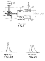
- the difference signals generated in the prior art detector for explosive and non-explosive vapors are shown in FIGS. 2a and 2b. It can be seen that the difference signal for explosives responds in the opposite direction to non-explosives.
- a logic gating circuit was arranged in the prior art detector to allow the signals to be presented at an output device such as an audible alarm or visual readout when the difference signal went negative while the signal strength was increasing.
- the limit of detection of the prior art device is one part of explosive vapor in 1010 parts of air. This is insufficient to detect the vapors from the "plastic" explosives largely comprised of cyclotrimethylenetrinitramine (otherwise known as RDX), and pentaerythritol tetranitrate (PETN). A sensitivity to one part of RDX in 1012 parts of air is required to provide a means of detection for the plastic explosives.
- the apparatus of the subject invention is a further improvement of the explosive detector described in U.S.Patent No.4,116,042, and shown schematically in Fig.1. More particularly, the subject invention is directed to a method and apparatus which will rapidly detect the vapors of all explosives including RDX and PETN. This has been achieved by a novel trapping system which has no moving parts, has extremely low volume and no metallic surfaces in the separation system.
- the system of the subject invention is capable of detecting dynamite and di nitro toluene (a component of commercial TNT), in less than 1 second and the plastic explosives in 10 to 20 seconds.
- an apparatus for detecting the presence of at least one selected constituent in a selected sample of air comprising: nozzle means for receiving air from the sample; suction means for creating a flow of the air through the nozzle, heating means for heating the flow of air in the nozzle membrane means in proximity to said nozzle for receiving at least the selected constituents in the air flowing through the nozzle; first and second chromatographic capillaries in proximity to the membrane for receiving the constituents diffused through the membrane, said capillaries being of substantially identical dimensions, said first capillary being internally coated with a layer of material which selectively delays the elution of the constituent; first and second detectors in communication with the respective first and second capillaries for generating signals in response to gases impinging therein; means for changing the temperature to which the air in the nozzle is heated; and signal processing means operatively connected to the detectors for identifying differences in phase of the signals detected by the first and second detectors respectively, whereby a difference in phase between selected signals generated
- a method for detecting the presence of a selected constituent in a flow of air comprising the steps of: generating a flow of said air; heating the air in said flow; providing a dimethyl silicone membrane in said flow for blocking selected unwanted constituents in said flow and permitting at least the selected constituent to diffuse through the membrane; directing the air diffused through said membrane into first and second dimensionally identical capillaries, said first capillary being coated internally with a layer of material which selectively delays the elution of the constituent; periodically raising the temperature of the air directed toward the membrane; generating signals for detecting the presence of materials passing through the capillaries; identifying phase differences existing at times when said constituents are known not to be present to identify a difference signal D; adjusting the generated signals by the amount of the difference signal D; and identifying actual phase differences for the adjusted signals to identify the presence of said constituent.
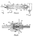
- the illustrated apparatus of the present invention is identified generally by the numeral 40 in FIG. 3.
- the apparatus 40 includes an inlet nozzle 42 into which sampled air being analyzed for the presence of explosive vapors is drawn and a membrane housing 44 into which the sampled air is directed by the inlet nozzle 42.
- the inlet nozzle 42 and the membrane housing 44 are shown in greater detail in FIG. 4.
- the inlet nozzle 42 Generally, during operation of the apparatus 40, air is drawn into the inlet nozzle 42 from the vicinity of a suspect object or package which is being inspected for possible terrorist explosive devices.
- the air flow through the inlet nozzle 42 is generated by a suction pump 46 which draws both the sampled air and an inert carrier gas, such as argon from a source 48 into the membrane housing 44.
- the inlet nozzle 42 preferably is made of all glass construction with thin walls which have a low thermal inertia.
- a coil of platinum wire 50 is held inside the full length of the glass inlet nozzle 42 and serves as a heater to warm the sampled air stream.
- An electric current is passed through the platinum wire coil 50, and the resistance of the wire 50 is measured by ohmmeter 52 to provide a measure of the temperature.
- the temperature of the inlet nozzle 42 is, by this means, controlled to a level which will allow the passage of most explosive vapors without adsorption in the walls of the inlet nozzle 42.
- the length of the inlet nozzle 42 is selected so that all of the sampled air reaches the temperature of the platinum wire coil 50 before striking the dimethyl silicone membrane 54 shown in FIG. 4.
- the sampled air is then drawn down the exhaust line 55 to a suction pump 46.
- the flow of air impinging on the membrane 54 maintains the membrane near to the temperature of the warm air. This temperature is sufficient to allow the diffusion through the membrane 54 of dynamite and the more volatile impurity materials in the other explosives. Most interfering atmospheric contaminants are more volatile than dynamite and will also pass directly through the membrane at this temperature. The vapors of TNT, RDX, and PETN are all trapped on the surface of the membrane 54 at this temperature and do not pass through the membrane 54 into the carrier gas stream.
- the vapors which do pass through the membrane 54 are swept by the carrier gas directly into two pure quartz chromatographic capillary columns 56 and 58.
- the capillary columns 56 and 58 are supported in an elongated heater jacket 60 defined by a Teflon® tube with a heater wire 62 in its wall.
- the heater jacket 60 is mounted in a housing 64 having a thermal insulation 66 between the heater jacket 60 and the housing 64.
- the capillary column 56 is coated with a polar chromatographic liquid, while the capillary column 58 is coated with a non-polar material:
- a dead volume 68 exists between the membrane 54 and the columns 56 and 58 and is kept extremely small, preferably below 50 micro litres and most preferably on the order of ten micro litres.
- the capillary columns 56 and 58 are maintained at a temperature between 150°C and 190°C which is much higher than previously used in the prior art described in U.S. Patent No. 4,116,042. At these temperatures, most materials travel down the non-polar column 58 at the speed of the carrier gas, i.e., they suffer no delay in the liquid coating in the wall of the capillary column 58. Most materials also travel down the polar capillary column 56 at the speed of the carrier gas.
- the geometry of the two columns 56 and 58 is kept identical so that these materials arrive at the detectors 70 and 72 simultaneously, and therefore respond simultaneously. If both detectors 70 and 72 have the same sensitivity, then no difference between the two detector responses is observed. This is true for all weak absorbers, such as oxygen, and all commonly occurring halogenated materials, such as refrigerants and solvents.
- any extremely low volatility explosives vapors such as RDX, PETN, or TNT which may be present, accumulate on the membrane 54.
- Increased heating is applied to the inlet nozzle 42 periodically (e.g. every 10-20 seconds) so that the temperature is rapidly increased from a first temperature between ambient and about 90°C to a second temperature of between about 150°C and 220°C.
- a second temperature of between about 150°C and 220°C.
- any explosive which has been deposited either in the nozzle 42 or on the membrane 54 is quickly evaporated and diffuses through the membrane 54 into the carrier gas stream.
- a high temperature is required to allow rapid diffusion to produce a sharp "peak" of vapor.
- Some explosives break down rapidly above 200°C, and so it is essential to maintain good control of the desorption temperature. This is again preferably achieved by using the platinum wire coil 50 as both the heater and thermometer in a closed loop temperature control system.
- the desorbed explosive travels down the two columns 56 and 58 and is delayed in the polar column 56 as in the prior art apparatus identified above. This causes a difference signal from the two detectors 70 and 72 which is used to signal the presence of explosives.
- the dynamic capacity and diffusion co-efficient of the membrane 54 for other interfering volatile impurities changes. This results in a response in each detector 70 and 72 at every heating cycle.
- the response can be completely balanced if the elution time or phase of the responses is identical and the sensitivity of the detectors 70 and 72 is identical. This ideal situation does not occur in practice.
- the sensitivity of detectors 70 and 72 may differ slightly and the phase of the two responses may also differ. Different diameters of the columns 56 and 58 or coating thicknesses thereon and temperature differentials between columns 56 and 58 may cause the elution time to differ.
- the subject apparatus 40 is uniquely adapted to maintain the phase and the responses identical for normal air background by a novel method and means for analyzing the signals.
- the similar signals containing random fluctuations are difficult to match in phase, but the time difference of the signal produced in each desorption cycle can be easily determined.
- the phase difference is first measured during a cycle in which normal background air is sampled. This is achieved by digitizing the signal in a micro processor system 74 and measuring the time to first respond after heating the membrane 54. This time difference can be checked in every cycle during which no response is obtained.
- a difference signal is then digitally computed after allowing for the phase shift between the two signals.
- a weighted mean gain calibration factor is calculated every cycle in which no response is obtained.
- the algorithm compensates for volatile impurity changes in the atmosphere and eliminates the noise in the difference signal due to such impurities.
- the apparatus and method described herein achieves several significant improvements to the sensitivity and selectivity.
- a greater concentration gain between atmosphere and the carrier gas is achieved due to the unrestricted path of sampled air and the extremely low volume of the desorption chamber. This allows a high air flow, F, at the same time as an extremely low carrier flow, f, and still provides extremely fast responses.
- C o the concentration reaching the detector
- C i the concentration in the sampled air
- T s the sampling time of the sampled air
- T p the peak width at half height of the desorbed peak; e in the trapping efficiency.
- T s can be chosen from 2 seconds to a few minutes, but in practice, sufficient sensitivity is achieved after 10 to 20 seconds.
- T p is adversely affected by the volume in the gas paths after the membrane and is also dependent on the rate of temperature rise in the membrane itself. Both of these points have been addressed in the design illustrated in FIGS. 3 and 4 to reduce T p to below 1 second.
- the ratio F/f can be in the region from 10 to 1000. At higher sample flow, F, the trapping efficiency is reduced and a high flow may cause dilution of the finite volume of vapor which is available. In practice, little or no concentration increase is gained beyond a flow ratio of 100.
- the apparatus 40 also achieves a much lower noise level which has resulted in the detection of much smaller quantities of explosive vapors. Furthermore, the apparatus 40 enables a reduction of interfering responses by cancellation in the dual detection system and ease of operation due to the automatic calibration of both gain and phase difference in the signal processing circuits of the processor 74 and the methods defined by the preceding algorithms. The combined effects of the apparatus 40 have led to the development of an apparatus capable of detecting the vapors from the most involatile of the plastic explosives used in terrorist bombs.
Landscapes
- Life Sciences & Earth Sciences (AREA)
- Health & Medical Sciences (AREA)
- Chemical & Material Sciences (AREA)
- General Physics & Mathematics (AREA)
- Engineering & Computer Science (AREA)
- Physics & Mathematics (AREA)
- Biochemistry (AREA)
- General Health & Medical Sciences (AREA)
- Immunology (AREA)
- Pathology (AREA)
- Analytical Chemistry (AREA)
- Remote Sensing (AREA)
- Molecular Biology (AREA)
- Biomedical Technology (AREA)
- General Life Sciences & Earth Sciences (AREA)
- Geophysics (AREA)
- Combustion & Propulsion (AREA)
- Food Science & Technology (AREA)
- Medicinal Chemistry (AREA)
- Sampling And Sample Adjustment (AREA)
Claims (9)
- Vorrichtung zur Erfassung der Anwesenheit von wenigstens einem gewählten Bestandteil in einer gewählten Luftprobe, gekennzeichnet durch:
eine Düse (42) zum Aufnehmen von Luft aus der Probe;
Saugmittel (46) zum Erzeugen eines Stromes der Luft durch die Düse (42);
Heizmittel (50) zum Erhitzen des Luftstromes in der Düse,
eine Membran (54) in der Nähe der genannten Düse (42) zum Aufnehmen wenigstens der gewählten Bestandteile in der durch die Düse strömenden Luft;
erste und zweite chromatografische Kapillare (56, 58) in der Nähe der Membran (54) zum Aufnehmen der durch die Membran diffundierten Bestandteile, wobei die Kapillare (56, 58) im wesentlichen gleich groß sind, wobei das genannte erste Kapillar (56) innen mit einer Schicht aus einem Material überzogen ist, das selektiv die Elution des Bestandteils verzögert;
erste und zweite Detektoren (70, 72) in Verbindung mit den entsprechenden ersten und zweiten Kapillaren (56, 58) zur Erzeugung von Signalen in Reaktion auf darauf auftreffende Gase;
Mittel zum Ändern der Temperatur, auf die die Luft in der Düse erhitzt wird; und
einen betriebsmäßig mit den Detektoren (70, 72) verbundenen Signalprozessor (74) zur Identifizierung von Phasenunterschieden der von dem ersten bzw. dem zweiten Detektor erfaßten Signale, wobei ein Phasenunterschied zwischen gewählten, durch den genannten ersten bzw. den genannten zweiten Detektor erzeugten Signalen die Anwesenheit des Gasbestandteils anzeigt. - Vorrichtung nach Anspruch 1, wobei das Heizmittel einen Platindraht (50) umfaßt.
- Vorrichtung nach Anspruch 1, wobei die Düse aus einer dünnwandigen Glasröhre ausgebildet ist und wobei das Heizmittel eine in der Düse angeordnete Platinspule (50) aufweist, wobei das genannte Heizmittel außerdem Mittel zum Messen des Widerstandes in der Platinspule und Mittel zum Ändern des elektrischen Stromes darin aufweist, wobei der elektrische Strom veränderlich ist und der Widerstand zum Regeln der Temperatur der Platinspule und somit zum Regeln der Temperatur der Luft gemessen wird.
- Vorrichtung nach Anspruch 3, wobei das Heizmittel die Luft in der Düse rasch von einer ersten Temperatur zwischen Umgebungstemperatur und etwa 90°C auf eine zweite Temperatur zwischen etwa 150°C und 220°C erhitzt.
- Vorrichtung nach Anspruch 1, weiterhin umfassend ein zweites Heizmittel zum Halten einer Temperatur der Kapillare zwischen 150°C und 190°C.
- Vorrichtung nach einem der Ansprüche 1 bis 5, weiterhin umfassend Mittel, um die Reaktionen der Detektoren auf allgemein vorkommende atmosphärische Schmutzstoffe stets identisch zu halten.
- Vorrichtung nach Anspruch 6, wobei das Mittel zum Identischhalten der Detektorreaktionen Mittel zum Errechnen eines Differenzsignals D zwischen den beiden Detektoren wie folgt aufweist:

- Verfahren zur Identifizierung der Anwesenheit eines gewählten Bestandteils in einem Luftstrom, gekennzeichnet durch die folgenden Schritte;
Erzeugen eines Stroms der genannten Luft;
Erhitzen der Luft in dem genannten Strom;
Einsetzen einer Dimethyl-Silikonmembran (54) in den genannten Strom, um gewählte unerwünschte Bestandteile in dem genannten Strom zurückzuhalten und wenigstens den gewählten Bestandteil durch die Membran diffundieren zu lassen;
Leiten der durch die genannte Membran (54) diffundierten Luft in erste und zweite größenmäßig identische Kapillare (56, 58), wobei das genannte erste Kapillar (56) innen mit einer Schicht aus einem Material überzogen ist, das selektiv die Elution des Bestandteils verzögert;
periodisches Erhitzen der zu der Membran geleiteten Luft;
Erzeugen von Signalen zum Erfassen der Anwesenheit von durch die Kapillare (56, 58) strömenden Materialien;
Ermitteln von Phasenunterschieden zu Zeiten, wenn bekannt ist, daß die genannten Bestandteile nicht vorhanden sind, um ein Differenzsignal D zu erhalten;
Justieren der generierten Signale um den Betrag des Differenzsignals D; und
Ermitteln der tatsächlichen Phasenunterschiede für die justierten Signale zur Ermittlung der Anwesenheit des genannten Bestandteils. - Verfahren nach Anspruch 8, wobei das Differenzsignal wie folgt errechnet wird:

Applications Claiming Priority (2)
| Application Number | Priority Date | Filing Date | Title |
|---|---|---|---|
| GB9006658A GB2242141A (en) | 1990-03-24 | 1990-03-24 | Method and apparatus for detecting low volatility atmospheric vapors |
| GB9006658 | 1990-03-24 |
Publications (2)
| Publication Number | Publication Date |
|---|---|
| EP0449518A1 EP0449518A1 (de) | 1991-10-02 |
| EP0449518B1 true EP0449518B1 (de) | 1994-12-07 |
Family
ID=10673220
Family Applications (1)
| Application Number | Title | Priority Date | Filing Date |
|---|---|---|---|
| EP91302493A Expired - Lifetime EP0449518B1 (de) | 1990-03-24 | 1991-03-21 | Verfahren und Apparat zur Detektion von leicht flüchtigen atmosphärischen Gasen |
Country Status (4)
| Country | Link |
|---|---|
| US (1) | US5027643A (de) |
| EP (1) | EP0449518B1 (de) |
| DE (1) | DE69105577D1 (de) |
| GB (1) | GB2242141A (de) |
Families Citing this family (26)
| Publication number | Priority date | Publication date | Assignee | Title |
|---|---|---|---|---|
| US5191211A (en) * | 1992-03-23 | 1993-03-02 | Bridgestone/Firestone, Inc. | Thermal desorption method for separating volatile additives from vulcanizable rubber |
| DE9208591U1 (de) * | 1992-07-01 | 1992-08-27 | Baltus, René, 5303 Bornheim | Vorrichtung zum Messen oder Sammeln der Menge eines in einer Flüssigkeit enthaltenen Gasanteils oder Feststoffes |
| US5482677A (en) * | 1993-05-14 | 1996-01-09 | Shell Oil Company | Thermally desorbable passive dosimeter |
| GB2291200A (en) | 1994-07-15 | 1996-01-17 | Ion Track Instr | Ion mobility spectrometer and method of operation for enhanced detection of narotics |
| US5719322A (en) * | 1996-09-20 | 1998-02-17 | Uop | Zeolitic capillary columns for gas chromatography |
| WO2002001528A2 (en) * | 2000-06-23 | 2002-01-03 | The Johns Hopkins University | Method and system for acoustic detection of aerosol dissemination |
| US6690005B2 (en) | 2000-08-02 | 2004-02-10 | General Electric Company | Ion mobility spectrometer |
| US6831273B2 (en) * | 2002-07-31 | 2004-12-14 | General Electric Company | Ion mobility spectrometers with improved resolution |
| US7338638B2 (en) * | 2002-08-19 | 2008-03-04 | Ge Homeland Protection, Inc. | Trapping materials for trace detection systems |
| US20040035187A1 (en) * | 2002-08-21 | 2004-02-26 | Allen William C. | Collection device for collecting the constituents of air |
| US6651520B1 (en) * | 2002-08-21 | 2003-11-25 | Preventure Security Solutions, Inc. | Interface between a piece of baggage and a preconcentrator |
| US20040035186A1 (en) * | 2002-08-21 | 2004-02-26 | Allen William C. | Interface between a collector and a package |
| US7456393B2 (en) * | 2003-04-10 | 2008-11-25 | Ge Homeland Protection, Inc. | Device for testing surfaces of articles for traces of explosives and/or drugs |
| US7047829B2 (en) * | 2004-08-30 | 2006-05-23 | General Electric Company | Device for testing traces of explosives and/or drugs |
| US7141786B2 (en) | 2004-09-08 | 2006-11-28 | General Electric Company | Particle sampling preconcentrator |
| DE602005010872D1 (de) * | 2005-09-20 | 2008-12-18 | Varian Spa | Vorrichtung und Verfahren zur Erfassung der Anwesentheit eines Prüfgases |
| US7448248B2 (en) * | 2005-12-12 | 2008-11-11 | Ge Homeland Protection Inc. | Calibration and verification tool and method for calibrating a detection apparatus |
| US20070158548A1 (en) * | 2006-01-09 | 2007-07-12 | Ge Security, Inc. | Ion trap mobility spectrometer |
| CA2649186A1 (en) * | 2006-04-18 | 2008-05-22 | Excellims Corporation | Chemical sampling and multi-function detection methods and apparatus |
| US7541577B2 (en) * | 2006-06-26 | 2009-06-02 | General Electric Company | Methods for analyzing ion mobility data |
| US20090203149A1 (en) | 2008-02-13 | 2009-08-13 | General Electric Company | Enhanced methods for gas and/or vapor phase analysis of biological assays |
| WO2011070574A1 (en) | 2009-12-07 | 2011-06-16 | S.T.I. Security Technology Integration Ltd. | Method and apparatus for inspecting a gas sample |
| US9170232B2 (en) | 2012-04-26 | 2015-10-27 | Teknoscan Systems Inc. | Substances detection system and method |
| DE102014004286B3 (de) | 2014-03-26 | 2015-04-16 | Peter Boeker | Strömungsfeld induzierte Temperatur-Gradienten-Gaschromatographie |
| CN111521728B (zh) * | 2020-05-15 | 2022-05-13 | 福州大学 | 具有多维浓度梯度的气体燃爆管道实验装置及方法 |
| US20220136941A1 (en) | 2020-11-02 | 2022-05-05 | Iontrap LLC | Method and apparatus for the rapid detection of air-borne viruses |
Family Cites Families (8)
| Publication number | Priority date | Publication date | Assignee | Title |
|---|---|---|---|---|
| US3225521A (en) * | 1962-06-04 | 1965-12-28 | Gulf Research Development Co | Serially connected thermochromatographic columns |
| US3568411A (en) * | 1969-03-18 | 1971-03-09 | Us Army | Chemosensor bomb detection device |
| GB1438504A (en) * | 1973-05-08 | 1976-06-09 | Analytical Instr Ltd | Method and apparatus for detecting a constituent in an atmosphere |
| GB1566256A (en) * | 1975-11-20 | 1980-04-30 | Analytical Instr Ltd | Method and apparatus for detecting a constituent in an atmosphere |
| DE3137765A1 (de) * | 1981-09-23 | 1983-03-31 | Bundesrepublik Deutschland, vertreten durch den Bundesminister der Verteidigung, dieser vertreten durch den Präsidenten des Bundesamtes für Wehrtechnik und Beschaffung, 5400 Koblenz | Verfahren und vorrichtung zur schnellen detektion, identifikation und quantifikation von spurenelementen in gasen, fluessigkeiten und festkoerpern |
| US4484061A (en) * | 1982-05-13 | 1984-11-20 | Sys-Tec, Inc. | Temperature control system for liquid chromatographic columns employing a thin film heater/sensor |
| GB2171328B (en) * | 1985-01-07 | 1988-10-19 | Loughborough Consult Ltd | Improvements in or relating to gas chromatography |
| US4759210A (en) * | 1986-06-06 | 1988-07-26 | Microsensor Systems, Inc. | Apparatus for gas-monitoring and method of conducting same |
-
1990
- 1990-03-24 GB GB9006658A patent/GB2242141A/en not_active Withdrawn
- 1990-04-03 US US07/503,698 patent/US5027643A/en not_active Expired - Lifetime
-
1991
- 1991-03-21 DE DE69105577T patent/DE69105577D1/de not_active Expired - Lifetime
- 1991-03-21 EP EP91302493A patent/EP0449518B1/de not_active Expired - Lifetime
Also Published As
| Publication number | Publication date |
|---|---|
| EP0449518A1 (de) | 1991-10-02 |
| GB2242141A (en) | 1991-09-25 |
| DE69105577D1 (de) | 1995-01-19 |
| US5027643A (en) | 1991-07-02 |
| GB9006658D0 (en) | 1990-05-23 |
Similar Documents
| Publication | Publication Date | Title |
|---|---|---|
| US5027643A (en) | Method and apparatus for detecting low volatility atmospheric vapors | |
| US4964309A (en) | Portal vapor detection system | |
| US4293316A (en) | Inlet system for a gas analyzer | |
| US4759210A (en) | Apparatus for gas-monitoring and method of conducting same | |
| CA2380477C (en) | Gas sensor with phased heaters for increased sensitivity | |
| US5889199A (en) | Portable leak detector | |
| US5014541A (en) | Continuous air monitoring apparatus and method | |
| US5083019A (en) | Preconcentrator for ion mobility spectrometer | |
| EP1546670B1 (de) | Detektor für gasleckagen mit geringer leistungsaufnahme | |
| US5108705A (en) | Vapor detection with high speed gas chromatography | |
| JP3487708B2 (ja) | ガスクロマトグラフにおける流量センサの補正方法および圧力センサの補正方法 | |
| US4148211A (en) | Sampling system for engine exhaust gas analysis apparatus | |
| CA2070619C (en) | Sample collection and inlet systems for gas chromatography apparatus | |
| JPH06194351A (ja) | ガスクロマトグラフシステム | |
| US4433982A (en) | Input head of a measuring or identification system for chemical agents | |
| GB2250633A (en) | Preconcentrating gas samples for analysis | |
| US3883739A (en) | Method for the qualitative and quantitative detection of vapours from low volatility compounds | |
| JP2000509487A (ja) | 運搬可能なイオン移動度分析計と共に使用する再循環濾過装置 | |
| US3675466A (en) | Sampling valve and system for the detection of predetermined compounds in air | |
| US5300758A (en) | Vapor detection with high speed gas chromatography | |
| Alekseenko et al. | Headspace gas-chromatographic determination of formaldehyde in urine | |
| EP4363825B1 (de) | System zur trennung eines analyten von einer probe | |
| US3940614A (en) | Method and apparatus for collection and analysis of mercury in the atmosphere | |
| US4077773A (en) | Method and apparatus for detection of monoalkylhalides | |
| US5846292A (en) | Chromatograph with column extraction |
Legal Events
| Date | Code | Title | Description |
|---|---|---|---|
| PUAI | Public reference made under article 153(3) epc to a published international application that has entered the european phase |
Free format text: ORIGINAL CODE: 0009012 |
|
| AK | Designated contracting states |
Kind code of ref document: A1 Designated state(s): DE ES FR GB |
|
| 17P | Request for examination filed |
Effective date: 19920116 |
|
| 17Q | First examination report despatched |
Effective date: 19940117 |
|
| GRAA | (expected) grant |
Free format text: ORIGINAL CODE: 0009210 |
|
| AK | Designated contracting states |
Kind code of ref document: B1 Designated state(s): DE ES FR GB |
|
| PG25 | Lapsed in a contracting state [announced via postgrant information from national office to epo] |
Ref country code: ES Free format text: THE PATENT HAS BEEN ANNULLED BY A DECISION OF A NATIONAL AUTHORITY Effective date: 19941207 Ref country code: FR Effective date: 19941207 |
|
| REF | Corresponds to: |
Ref document number: 69105577 Country of ref document: DE Date of ref document: 19950119 |
|
| PG25 | Lapsed in a contracting state [announced via postgrant information from national office to epo] |
Ref country code: DE Effective date: 19950308 |
|
| EN | Fr: translation not filed | ||
| PLBE | No opposition filed within time limit |
Free format text: ORIGINAL CODE: 0009261 |
|
| STAA | Information on the status of an ep patent application or granted ep patent |
Free format text: STATUS: NO OPPOSITION FILED WITHIN TIME LIMIT |
|
| 26N | No opposition filed | ||
| REG | Reference to a national code |
Ref country code: GB Ref legal event code: 732E |
|
| REG | Reference to a national code |
Ref country code: GB Ref legal event code: IF02 |
|
| REG | Reference to a national code |
Ref country code: GB Ref legal event code: 732E |
|
| PGFP | Annual fee paid to national office [announced via postgrant information from national office to epo] |
Ref country code: GB Payment date: 20090403 Year of fee payment: 19 |
|
| GBPC | Gb: european patent ceased through non-payment of renewal fee |
Effective date: 20100321 |
|
| PG25 | Lapsed in a contracting state [announced via postgrant information from national office to epo] |
Ref country code: GB Free format text: LAPSE BECAUSE OF NON-PAYMENT OF DUE FEES Effective date: 20100321 |