EP0449429A2 - A bath - Google Patents
A bath Download PDFInfo
- Publication number
- EP0449429A2 EP0449429A2 EP91301688A EP91301688A EP0449429A2 EP 0449429 A2 EP0449429 A2 EP 0449429A2 EP 91301688 A EP91301688 A EP 91301688A EP 91301688 A EP91301688 A EP 91301688A EP 0449429 A2 EP0449429 A2 EP 0449429A2
- Authority
- EP
- European Patent Office
- Prior art keywords
- seat
- bath
- actuator
- bath tub
- lifting column
- Prior art date
- Legal status (The legal status is an assumption and is not a legal conclusion. Google has not performed a legal analysis and makes no representation as to the accuracy of the status listed.)
- Withdrawn
Links
Images


Classifications
-
- A—HUMAN NECESSITIES
- A61—MEDICAL OR VETERINARY SCIENCE; HYGIENE
- A61G—TRANSPORT, PERSONAL CONVEYANCES, OR ACCOMMODATION SPECIALLY ADAPTED FOR PATIENTS OR DISABLED PERSONS; OPERATING TABLES OR CHAIRS; CHAIRS FOR DENTISTRY; FUNERAL DEVICES
- A61G7/00—Beds specially adapted for nursing; Devices for lifting patients or disabled persons
- A61G7/10—Devices for lifting patients or disabled persons, e.g. special adaptations of hoists thereto
- A61G7/1001—Devices for lifting patients or disabled persons, e.g. special adaptations of hoists thereto specially adapted for specific applications
- A61G7/1003—Devices for lifting patients or disabled persons, e.g. special adaptations of hoists thereto specially adapted for specific applications mounted on or in combination with a bath-tub
-
- A—HUMAN NECESSITIES
- A61—MEDICAL OR VETERINARY SCIENCE; HYGIENE
- A61G—TRANSPORT, PERSONAL CONVEYANCES, OR ACCOMMODATION SPECIALLY ADAPTED FOR PATIENTS OR DISABLED PERSONS; OPERATING TABLES OR CHAIRS; CHAIRS FOR DENTISTRY; FUNERAL DEVICES
- A61G7/00—Beds specially adapted for nursing; Devices for lifting patients or disabled persons
- A61G7/10—Devices for lifting patients or disabled persons, e.g. special adaptations of hoists thereto
- A61G7/1013—Lifting of patients by
- A61G7/1019—Vertical extending columns or mechanisms
-
- A—HUMAN NECESSITIES
- A61—MEDICAL OR VETERINARY SCIENCE; HYGIENE
- A61G—TRANSPORT, PERSONAL CONVEYANCES, OR ACCOMMODATION SPECIALLY ADAPTED FOR PATIENTS OR DISABLED PERSONS; OPERATING TABLES OR CHAIRS; CHAIRS FOR DENTISTRY; FUNERAL DEVICES
- A61G7/00—Beds specially adapted for nursing; Devices for lifting patients or disabled persons
- A61G7/10—Devices for lifting patients or disabled persons, e.g. special adaptations of hoists thereto
- A61G7/1049—Attachment, suspending or supporting means for patients
- A61G7/1059—Seats
-
- A—HUMAN NECESSITIES
- A61—MEDICAL OR VETERINARY SCIENCE; HYGIENE
- A61G—TRANSPORT, PERSONAL CONVEYANCES, OR ACCOMMODATION SPECIALLY ADAPTED FOR PATIENTS OR DISABLED PERSONS; OPERATING TABLES OR CHAIRS; CHAIRS FOR DENTISTRY; FUNERAL DEVICES
- A61G7/00—Beds specially adapted for nursing; Devices for lifting patients or disabled persons
- A61G7/10—Devices for lifting patients or disabled persons, e.g. special adaptations of hoists thereto
- A61G7/1073—Parts, details or accessories
- A61G7/1076—Means for rotating around a vertical axis
-
- A—HUMAN NECESSITIES
- A61—MEDICAL OR VETERINARY SCIENCE; HYGIENE
- A61G—TRANSPORT, PERSONAL CONVEYANCES, OR ACCOMMODATION SPECIALLY ADAPTED FOR PATIENTS OR DISABLED PERSONS; OPERATING TABLES OR CHAIRS; CHAIRS FOR DENTISTRY; FUNERAL DEVICES
- A61G7/00—Beds specially adapted for nursing; Devices for lifting patients or disabled persons
- A61G7/10—Devices for lifting patients or disabled persons, e.g. special adaptations of hoists thereto
- A61G7/1073—Parts, details or accessories
- A61G7/1082—Rests specially adapted for
- A61G7/1092—Rests specially adapted for the arms
Definitions
- This invention relates to a bath comprising a bath tub and apparatus for assisting persons, particularly elderly and physically disabled persons, into and out of the bath tub.
- Lifting devices are known for assisting elderly and physically disabled persons into and out of a bath.
- One such lifting device is designed to be fixed to the floor beside the bath. This has its place, but it takes up space which is often at a premium.
- Several other known lifting devices are designed as non-permanent fixtures and can be placed in or removed from a standard bath at will. Again these have their place, but these lifting devices have a seat which can only be raised and lowered and cannot swivel, with the result that they have limited application and are generally not suitable for wheelchair bound persons.
- a bath comprising a bath tub and apparatus for assisting persons into and out of the bath tub, the apparatus comprising a lifting column, a seat supported by the lifting column, a first actuator mounted with respect to the lifting column for raising and lowering the seat relative to the bath tub, and a second actuator for angularly displacing the lifting column, thereby causing the seat to swivel, when the seat is in an elevated position relative to the bath tub.
- the lifting column extends through a hole in one end of the bath tub.
- the first and second actuators are electro-mechanical or electro-hydraulic actuators.
- the lifting column is in the form of a telescopic mast having a lower part fixed against vertical movement and an upper part which can be extended and retracted relative to the lower part by the first actuator.
- the second actuator comprises two mutually telescopic parts which are extendible and retractable relative to one another in a horizontal plane, one of the parts being pivotally connected to a fixed point, e.g. a frame of the bath, and the other part being pivotally connected to an arm secured to and extending horizontally from the lifting column.
- a fixed point e.g. a frame of the bath
- the apparatus comprises a control device for operating the first and second actuators so as to raise the seat from a lowered to an elevated position and to then swivel the seat in one direction to a position in which the seat extends over a rim of the bath tub and so as to swivel the seat in a opposite direction and to then lower the seat into the bath tub.
- the control device may include sensors, e.g. limit switches, for sensing when the seat reaches a fully elevated position in which it can then be swivelled without fouling the bath tub and for sensing when the seat reaches an angular position in which it can be lowered into the tub without fouling the sides thereof.
- the control device may provide an automatic delay between raising and swivelling the seat, and between swivelling and lowering the seat, to lessen the abruptness of the transitions between raising and swivelling, and between swivelling and lowering of the seat.
- the bath tub has a shallow well for receiving a squab portion of the seat when the latter is in a lowered position.
- the seat has arm rests, one of which is displaceable to provide ease of access to the seat.
- the bath shown therein comprises a bath tub 10, a frame 11 supporting the tub 10, and apparatus 12 for assisting physically disabled persons into and out of the tub 10.
- the apparatus 12 comprises a lifting column in the form of a telescopic mast 13 supported in an upright position by the frame 11 and the bath tub 10, and a seat 14 supported by the mast 13.
- the mast 13 comprises a lower mast part 15 which is mounted beneath the bath tub 10 and concealed from view behind bath panels 9, and an upper mast part 16 which extends through a hole in the top of an upwardly extending bulge 17 formed centrally in an end portion of the rim of the bath tub 10.
- the upper mast part 16 is slidable in the lower mast part 15 between a retracted position (shown in Figures 1, 3 and 5) and an extended position (shown in Figures 2 and 6).
- the seat 14 is of a semi-rigid plastics material having a metal plate 18 moulded into the back of the seat and two armrests 20 and 21 pivotally connected to the plate 18 so that they can be swung upwards.
- the seat is firmly secured to the upper end of the upper mast part 16 by a bracket 19 which is secured to the plate 18 and to the upper end of the upper mast part.
- the mast 13 is supported for angular movement about a vertical (or substantially vertical) axis by sleeve bearings 21 a and 21 b provided in a bush 22, and by a sleeve bearing 23 provided in a plate-like housing 24.
- the bush 22 is mounted in a hole in the top of bulge 17 and the housing 24 is secured to a section 11 a of the frame 11.
- the lower mast part is prevented from moving axially (i.e. vertically) by the bush 22 and the plate-like housing 24, and the upper mast part 16 is slidable in the upper bearing 21 a so that it can be extended and retracted relative to the lower mast part 15 by an electro-mechanical actuator 26 provided for the most part within the mast 13.
- a slider block 25 is fixed to the outside of the upper mast part 16 and co-operates with an outwardly projecting, longitudinally extending slideway 15 a provided in the lower mast part 15, to prevent relative angular movement of the upper and lower mast parts.
- the actuator 26 comprises a threaded rod 27, a nut 28 co-operable with the rod 27, an electric motor 29 and reduction gearbox 51, coupled to the threaded rod 27 by a toothed belt and pulley drive 30, a tube 31, and an overrun clutch 32 between the nut 28 and the tube 31.
- a cylindrical plug 33 is secured to the upper end of the tube 31 and this plug 33 is connected to the upper mast part 16 by a transverse pin 33 a and to the bracket 19 by a threaded bolt 33 b .
- the overrun clutch 32 comprises a first clutch member 34 integral with the nut 28, a second clutch member 35 fixed to the lower end of the tube 31, and a helical spring 36 mounted about the two clutch members 34 and 35.
- the spring 36 will tighten and the clutch members 34 and 35 will be drawn together. This will ensure that the nut 28 cannot rotate and it therefore rides upwards on the threaded rod 27 and extends the mast 13.
- the spring 36 will slacken. The nut 28 can then rotate with the threaded rod 29.
- the mast 13 can be displaced angularly by a second electro-mechanical actuator 37 in order to swivel the seat 14 when the latter is in an elevated position.
- the actuator 37 has two telescopically extendible/retractable parts 38 and 39, and is of a type made by Linak A/S of Denmark under model no. LA 22.5.
- the actuator part 38 is pivotally connected to the frame 11 and the actuator part 39 is pivotally connected to a lever arm 40 projecting radially from the lower end of the lower mast part 15.
- a control device for the actuators 26 and 37 operates in response to pneumatic signals transmitted along air lines 41 from a remote controller 42.
- the control device is designed to move the seat 14 from a bathing position as shown in Figure 1 to a mounting position as shown in Figure 2 and vice versa , while, in each case, an operator (usually the user) holds an appropriate button 43, 44 on the controller 42 in a depressed condition.
- the control device also includes three limit switches 45, 46 and 47 (shown diagrammatically in Figure 6).
- Switch 45 senses the fully extended condition of the mast 13; switch 46 senses the extended condition of the actuator 37, that is when the mast 13 is in a position in which the seat 14 is in the bath tub 10 or in a position in which it can be lowered into the bath tub 10 without fouling the sides of the tub 10; and switch 47 senses the fully retracted condition of the actuator 37.
- the appropriate button 43 on the controller 42 is depressed and held depressed.
- the control device will first energise the motor 29 of the actuator 26 so that an elevated position in which it can be swivelled over the rim of the bath tub 10.
- the limit switch 45 will change condition when the seat 14 reaches this position, and the motor 29 will be de-energised.
- the control device will energise the actuator 37.
- the two parts 38, 39 of the actuator 37 will retract relative to one another and the lever arm 26 will move clockwise as viewed in plan to angularly displace the mast 13 about its axis and swivel the seat 14 over the rim of the bath tub 10.
- the limit switch 46 will change condition.
- the seat 14 will continue to swivel until the button 43 is released or the seat 14 reaches an end of travel position, such as that shown in Figure 2, when the limit switch 47 will change condition and the actuator 37 will be de-energised.
- the seat 14 will be swivelled to the position shown in Figure 2 if it is to be mounted by a non-wheelchair bound person, but transfer from a wheelchair to the seat 14 is more easily accomplished if the seat 14 is swivelled through a smaller angle, and in order to facilitate transfer from a wheelchair to the seat 14, the arm rest 20 is swung upwards and out of the way.
- the arm rest 20 When the user is safely on the seat 14, the arm rest 20 is returned to the position shown in Figures 1 and 2, and the button 44 on the controller 42 is depressed. This will energise the actuator 37.
- the two parts 38, 39 of the actuator 37 will extend relative to clockwise, as viewed in plan, to angularly displace the mast 13 about its axis and swivel the seat 14 back over the rim of the bath tub 10.
- the movement of the seat 14 can be temporarily arrested at any time by releasing the button 44, to allow the user or an attendant to lift the user's legs over the side of the bath tub 10.
- the limit switch 46 When the seat 14 reaches an end of travel position, the limit switch 46 will revert to its original condition and the actuator 37 will be de-energised.
- the control device will energise the actuator 26.
- the mast 13 will retract.
- the limit switch 45 will revert to its original condition and the seat 14, together with the user, will be lowered into the bath tub 10.
- the user can be assisted out of the bath by again depressing the button 43 to again raise and then swivel the seat 14.
- the bath tub 10 has a shallow well 48 for receiving the squab portion of the seat 14 when the latter is its lowermost position.
- the bath is also provided with control valves 49 for the hot and cold water supply, midway along one side of the bath so that these are within easy reach of a user, and hand holds 50.
- actuators 26 and 37 could be electro-hydraulic actuators instead of being electro-mechanical actuators.
- arm rest 21 could be fixed and only arm rest 20 pivotable relative to the seat.
Abstract
Description
- This invention relates to a bath comprising a bath tub and apparatus for assisting persons, particularly elderly and physically disabled persons, into and out of the bath tub.
- Lifting devices are known for assisting elderly and physically disabled persons into and out of a bath. One such lifting device is designed to be fixed to the floor beside the bath. This has its place, but it takes up space which is often at a premium. Several other known lifting devices are designed as non-permanent fixtures and can be placed in or removed from a standard bath at will. Again these have their place, but these lifting devices have a seat which can only be raised and lowered and cannot swivel, with the result that they have limited application and are generally not suitable for wheelchair bound persons. It is also known to provide lifting devices as permanent fixtures in a bath, but the seats of these known devices are freely swivellable when in an elevated position, and this can prove hazardous particularly to wheelchair bound persons as they attempt to transfer from a wheelchair to the seat of the lifting device.
- According to the present invention, there is provided a bath comprising a bath tub and apparatus for assisting persons into and out of the bath tub, the apparatus comprising a lifting column, a seat supported by the lifting column, a first actuator mounted with respect to the lifting column for raising and lowering the seat relative to the bath tub, and a second actuator for angularly displacing the lifting column, thereby causing the seat to swivel, when the seat is in an elevated position relative to the bath tub.
- Preferably, the lifting column extends through a hole in one end of the bath tub.
- Conveniently, the first and second actuators are electro-mechanical or electro-hydraulic actuators.
- Advantageously, the lifting column is in the form of a telescopic mast having a lower part fixed against vertical movement and an upper part which can be extended and retracted relative to the lower part by the first actuator.
- Preferably, the second actuator comprises two mutually telescopic parts which are extendible and retractable relative to one another in a horizontal plane, one of the parts being pivotally connected to a fixed point, e.g. a frame of the bath, and the other part being pivotally connected to an arm secured to and extending horizontally from the lifting column.
- Preferably, the apparatus comprises a control device for operating the first and second actuators so as to raise the seat from a lowered to an elevated position and to then swivel the seat in one direction to a position in which the seat extends over a rim of the bath tub and so as to swivel the seat in a opposite direction and to then lower the seat into the bath tub. In this case, the control device may include sensors, e.g. limit switches, for sensing when the seat reaches a fully elevated position in which it can then be swivelled without fouling the bath tub and for sensing when the seat reaches an angular position in which it can be lowered into the tub without fouling the sides thereof. The control device may provide an automatic delay between raising and swivelling the seat, and between swivelling and lowering the seat, to lessen the abruptness of the transitions between raising and swivelling, and between swivelling and lowering of the seat.
- Conveniently, the bath tub has a shallow well for receiving a squab portion of the seat when the latter is in a lowered position.
- Preferably, the seat has arm rests, one of which is displaceable to provide ease of access to the seat.
- The invention will now be more particularly described, by way of example only, with reference to the accompanying drawings, in which:-
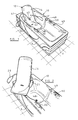
- Figure 1 is a perspective view of one embodiment of a bath according to the present invention, with the seat in a lowered position,
- Figure 2 is a fragmentary perspective view showing the seat of Figure 1 in a position in which it can be mounted by an elderly or physically disabled person,
- Figure 3 is a vertical section taken through part of the bath shown in Figure 1 on an enlarged scale,
- Figure 4 is an underneath plan view of part of the bath shown in Figure 1 on an enlarged scale,
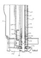
- Figure 5 is a detailed vertical section through the lower end of the lifting column and actuator therein on a much enlarged scale, and
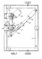
- Figure 6 is a schematic view of the lifting apparatus on its own.
- Referring to the drawings, the bath shown therein comprises a
bath tub 10, aframe 11 supporting thetub 10, andapparatus 12 for assisting physically disabled persons into and out of thetub 10. - The
apparatus 12 comprises a lifting column in the form of atelescopic mast 13 supported in an upright position by theframe 11 and thebath tub 10, and aseat 14 supported by themast 13. - The
mast 13 comprises alower mast part 15 which is mounted beneath thebath tub 10 and concealed from view behindbath panels 9, and anupper mast part 16 which extends through a hole in the top of an upwardly extendingbulge 17 formed centrally in an end portion of the rim of thebath tub 10. Theupper mast part 16 is slidable in thelower mast part 15 between a retracted position (shown in Figures 1, 3 and 5) and an extended position (shown in Figures 2 and 6). - The
seat 14 is of a semi-rigid plastics material having ametal plate 18 moulded into the back of the seat and twoarmrests plate 18 so that they can be swung upwards. The seat is firmly secured to the upper end of theupper mast part 16 by abracket 19 which is secured to theplate 18 and to the upper end of the upper mast part. - As best shown in Figures 3 & 5, the
mast 13 is supported for angular movement about a vertical (or substantially vertical) axis bysleeve bearings 21a and 21b provided in abush 22, and by a sleeve bearing 23 provided in a plate-like housing 24. Thebush 22 is mounted in a hole in the top ofbulge 17 and thehousing 24 is secured to a section 11a of theframe 11. The lower mast part is prevented from moving axially (i.e. vertically) by thebush 22 and the plate-like housing 24, and theupper mast part 16 is slidable in the upper bearing 21a so that it can be extended and retracted relative to thelower mast part 15 by an electro-mechanical actuator 26 provided for the most part within themast 13. - A
slider block 25 is fixed to the outside of theupper mast part 16 and co-operates with an outwardly projecting, longitudinally extending slideway 15a provided in thelower mast part 15, to prevent relative angular movement of the upper and lower mast parts. - The
actuator 26 comprises a threadedrod 27, anut 28 co-operable with therod 27, anelectric motor 29 and reduction gearbox 51, coupled to the threadedrod 27 by a toothed belt andpulley drive 30, atube 31, and anoverrun clutch 32 between thenut 28 and thetube 31. - A
cylindrical plug 33 is secured to the upper end of thetube 31 and thisplug 33 is connected to theupper mast part 16 by a transverse pin 33a and to thebracket 19 by a threaded bolt 33b. - As shown in Figure 5, the
overrun clutch 32 comprises afirst clutch member 34 integral with thenut 28, asecond clutch member 35 fixed to the lower end of thetube 31, and ahelical spring 36 mounted about the twoclutch members motor 29 is rotated to raise theseat 14, thespring 36 will tighten and theclutch members nut 28 cannot rotate and it therefore rides upwards on the threadedrod 27 and extends themast 13. When themotor 29 is rotated to lower theseat 14, if theseat 14 meets with an obstruction, thespring 36 will slacken. Thenut 28 can then rotate with the threadedrod 29. - The
mast 13 can be displaced angularly by a second electro-mechanical actuator 37 in order to swivel theseat 14 when the latter is in an elevated position. Theactuator 37 has two telescopically extendible/retractable parts actuator part 38 is pivotally connected to theframe 11 and theactuator part 39 is pivotally connected to alever arm 40 projecting radially from the lower end of thelower mast part 15. Thus, it will be seen that when the twoparts actuator 37 are retracted, with the seat in an elevated position, themast 13 will turn clockwise as viewed in plan, and theseat 14 will swivel over a side portion of the rim of thebath tub 10, as shown in Figure 2. - A control device for the
actuators air lines 41 from aremote controller 42. The control device is designed to move theseat 14 from a bathing position as shown in Figure 1 to a mounting position as shown in Figure 2 and vice versa, while, in each case, an operator (usually the user) holds anappropriate button 43, 44 on thecontroller 42 in a depressed condition. The control device also includes threelimit switches mast 13; switch 46 senses the extended condition of theactuator 37, that is when themast 13 is in a position in which theseat 14 is in thebath tub 10 or in a position in which it can be lowered into thebath tub 10 without fouling the sides of thetub 10; and switch 47 senses the fully retracted condition of theactuator 37. - Thus, in operation, in order to raise the
seat 14 from a bathing position to a mounting position, theappropriate button 43 on thecontroller 42 is depressed and held depressed. The control device will first energise themotor 29 of theactuator 26 so that an elevated position in which it can be swivelled over the rim of thebath tub 10. Thelimit switch 45 will change condition when theseat 14 reaches this position, and themotor 29 will be de-energised. After a short deliberate delay provided by electronic circuitry, the control device will energise theactuator 37. The twoparts actuator 37 will retract relative to one another and thelever arm 26 will move clockwise as viewed in plan to angularly displace themast 13 about its axis and swivel theseat 14 over the rim of thebath tub 10. As theseat 14 starts to swivel thelimit switch 46 will change condition. Theseat 14 will continue to swivel until thebutton 43 is released or theseat 14 reaches an end of travel position, such as that shown in Figure 2, when thelimit switch 47 will change condition and theactuator 37 will be de-energised. Theseat 14 will be swivelled to the position shown in Figure 2 if it is to be mounted by a non-wheelchair bound person, but transfer from a wheelchair to theseat 14 is more easily accomplished if theseat 14 is swivelled through a smaller angle, and in order to facilitate transfer from a wheelchair to theseat 14, thearm rest 20 is swung upwards and out of the way. - When the user is safely on the
seat 14, thearm rest 20 is returned to the position shown in Figures 1 and 2, and the button 44 on thecontroller 42 is depressed. This will energise theactuator 37. The twoparts actuator 37 will extend relative to clockwise, as viewed in plan, to angularly displace themast 13 about its axis and swivel theseat 14 back over the rim of thebath tub 10. The movement of theseat 14 can be temporarily arrested at any time by releasing the button 44, to allow the user or an attendant to lift the user's legs over the side of thebath tub 10. When theseat 14 reaches an end of travel position, thelimit switch 46 will revert to its original condition and theactuator 37 will be de-energised. After a short deliberate delay provided by electronic circuitry, the control device will energise theactuator 26. Themast 13 will retract. Thelimit switch 45 will revert to its original condition and theseat 14, together with the user, will be lowered into thebath tub 10. After bathing, the user can be assisted out of the bath by again depressing thebutton 43 to again raise and then swivel theseat 14. - As shown, the
bath tub 10 has ashallow well 48 for receiving the squab portion of theseat 14 when the latter is its lowermost position. The bath is also provided withcontrol valves 49 for the hot and cold water supply, midway along one side of the bath so that these are within easy reach of a user, and hand holds 50. - The embodiment described above is given by way of example only and various modifications will be apparent to persons skilled in the art without departing from the scope of the invention. For example, one or both of the
actuators arm rest 21 could be fixed and only armrest 20 pivotable relative to the seat.
Claims (10)
- A bath comprising a bath tub (10) and apparatus (12) for assisting persons into and out of the bath tub, the apparatus comprising a lifting column (13), a seat (14) supported by the lifting column, and a first actuator (26) mounted with respect to the lifting column for raising and lowering the seat relative to the bath tub, characterised in that the apparatus further comprises a second actuator (37) for angularly displacing the lifting column, thereby causing the seat to swivel when the seat is in an elevated position relative to the bath tub.
- A bath as claimed in claim 1, wherein the first and second actuators (26 and 37) are electrically powered.
- A bath as claimed in claim 2, wherein at least one of the actuators (26,37) is an electro-mechanical actuator.
- A bath as claimed in any one of the preceding claims, wherein the lifting column is in the form of a telescopic mast (13) having a lower part (15) fixed against vertical movement and an upper part (16) which can be extended and retracted relative to the lower part by the first actuator.
- A bath as claimed in any one of the preceding claims, wherein the second actuator (37) comprises two mutually telescopic parts (38,39) which are extendable and retractable relative to one another in a horizontal plane, one of the parts (38) being pivotally connected to a fixed point and the other part (39) being pivotally connected to an arm (40) secured to and extending horizontally from the lifting column.
- A bath as claimed in any one of the preceding claims, wherein the apparatus comprises a control device for operating the first and second actuators (26 and 27) so as to raise the seat (14) from a lowered to an elevated position and to then swivel the seat in one direction to a position in which the seat extends over a rim of the bath tub, and so as to swivel the seat in an opposite direction and to then lower the seat into the bath tub.
- A bath as claimed in claim 6, wherein the control device includes sensors (45,46) for sensing when the seat reaches a fully elevated position in which it can then be swivelled without fouling the bath tub and for sensing when the seat reaches an angular position in which it can be lowered into the tub without fouling the sides thereof.
- A bath as claimed in claim 6 or claim 7, wherein the control device includes means for providing an automatic delay between raising and swivelling the seat, and between swivelling and lowering the seat.
- A bath as claimed in any one of the preceding claims, wherein the lifting column (13) extends through a hole in one end of the bath tub.
- A bath as claimed in any one of the preceding claims, wherein the seat has arm rests (20,21), one of which is displaceable to provide ease of access to the seat.
Applications Claiming Priority (2)
| Application Number | Priority Date | Filing Date | Title |
|---|---|---|---|
| GB9006507 | 1990-03-23 | ||
| GB909006507A GB9006507D0 (en) | 1990-03-23 | 1990-03-23 | A bath |
Publications (2)
| Publication Number | Publication Date |
|---|---|
| EP0449429A2 true EP0449429A2 (en) | 1991-10-02 |
| EP0449429A3 EP0449429A3 (en) | 1991-12-27 |
Family
ID=10673107
Family Applications (1)
| Application Number | Title | Priority Date | Filing Date |
|---|---|---|---|
| EP19910301688 Withdrawn EP0449429A3 (en) | 1990-03-23 | 1991-02-28 | A bath |
Country Status (4)
| Country | Link |
|---|---|
| US (1) | US5146638A (en) |
| EP (1) | EP0449429A3 (en) |
| JP (1) | JPH04221562A (en) |
| GB (2) | GB9006507D0 (en) |
Cited By (5)
| Publication number | Priority date | Publication date | Assignee | Title |
|---|---|---|---|---|
| FR2682034A1 (en) * | 1991-10-07 | 1993-04-09 | Allia | Bath with seat for the handicapped |
| WO2006058652A1 (en) * | 2004-12-01 | 2006-06-08 | Palesta Anstalt | Bath lift |
| FR2962900A1 (en) * | 2010-07-23 | 2012-01-27 | Nimitech Composites | Basin for therapeutic treatment of fibromyalgia of e.g. thighs, of patient in hospital, has central boss provided with treatment fluid distribution orifices oriented to treat interior of legs, thighs and abdomen |
| FR2962899A1 (en) * | 2010-07-23 | 2012-01-27 | Nimitech Composites | Hydrotherapy treating tank for treating e.g. legs of old people in fibromyalgia treatment at hospital, has rising mechanism allowing patient to sit up and sit down in sitting position in tank and to arise from tank after sit up in seat |
| EP3040063A1 (en) * | 2014-12-29 | 2016-07-06 | Robotics Care AB | Bathing aid |
Families Citing this family (18)
| Publication number | Priority date | Publication date | Assignee | Title |
|---|---|---|---|---|
| JPH059253A (en) * | 1991-02-19 | 1993-01-19 | Sanyo Chem Ind Ltd | Solid polyelectrolyte |
| GB9124728D0 (en) * | 1991-11-21 | 1992-01-15 | Hampshire Med Dev | Baths for use by physically handicapped persons |
| US5218727A (en) * | 1992-02-26 | 1993-06-15 | Industrial Design & Mfg., Inc. | Above ground spa lift for the handicapped |
| GB9306882D0 (en) * | 1993-04-01 | 1993-05-26 | Parker Roy | Baths |
| US5465433A (en) * | 1994-06-06 | 1995-11-14 | Nolan; J. David | Seat lift |
| US6256807B1 (en) * | 1998-05-28 | 2001-07-10 | Silver Crown Associates Limited | Bath lift |
| US6170612B1 (en) | 1999-06-22 | 2001-01-09 | Spectrum Distributors, Inc. | Swimming pool lift |
| US6643861B2 (en) | 2000-04-14 | 2003-11-11 | Freedom Bath, Inc. | Bath lifting system |
| US20040098801A1 (en) * | 2000-04-14 | 2004-05-27 | Pop-In Pop-Out, Inc | Bath lifting system |
| US6397409B1 (en) | 2000-04-14 | 2002-06-04 | Freedom Bath, Inc. | Bath lifting system |
| US20040231043A1 (en) * | 2000-04-14 | 2004-11-25 | Pop-In Pop-Out, Inc. | Bath lifting system |
| US7055187B1 (en) | 2004-01-23 | 2006-06-06 | Fields J Burford | Bathing apparatus with bathtub and banister |
| US7197775B2 (en) * | 2004-11-16 | 2007-04-03 | William Steadman | Bath lift |
| US8307471B2 (en) * | 2009-09-10 | 2012-11-13 | Axcess Innovations Inc. | Bather movement apparatus |
| US20110131720A1 (en) * | 2009-12-09 | 2011-06-09 | David Franklin Dean | Wall Mounted Lift Chair |
| US20200179201A1 (en) * | 2018-12-05 | 2020-06-11 | Andrew Dancy | Apparatus and method for a bather support system |
| US11318058B2 (en) * | 2019-04-10 | 2022-05-03 | Malcolm Berg | Lift for water entry/exit and methods of manufacture and use thereof |
| CN110063885B (en) * | 2019-04-30 | 2021-03-26 | 中国人民解放军陆军军医大学第一附属医院 | Cleaning pool for burns |
Citations (4)
| Publication number | Priority date | Publication date | Assignee | Title |
|---|---|---|---|---|
| DE2512595A1 (en) * | 1974-04-02 | 1975-10-23 | Toscano Gambini | SEAT LIFT FOR BATHTUBS |
| DE3511267A1 (en) * | 1985-03-28 | 1986-10-09 | Paul Hettmer | Bathing device for the disabled |
| WO1988000820A1 (en) * | 1986-08-01 | 1988-02-11 | David Boublil | Lift for putting a handicapped person into the water of a swimming bath or a pool for reeducation purposes |
| FR2614527A1 (en) * | 1987-04-30 | 1988-11-04 | Boublil David | Automatic seat for bath entry for handicapped people |
Family Cites Families (15)
| Publication number | Priority date | Publication date | Assignee | Title |
|---|---|---|---|---|
| US2187283A (en) * | 1937-10-25 | 1940-01-16 | Joseph A Scheutz | Elevator apparatus |
| GB744155A (en) * | 1953-06-18 | 1956-02-01 | Erling Saelen | An improved invalid lifting and transferring device |
| US3078473A (en) * | 1960-11-28 | 1963-02-26 | William A Daniels | Bath tub lift |
| US3078475A (en) * | 1961-06-23 | 1963-02-26 | Robert W Turner | Electrically operated bathtub seat |
| US3268918A (en) * | 1963-09-06 | 1966-08-30 | Batty Frederick Albert | Invalid lifting apparatus |
| US3815163A (en) * | 1972-01-07 | 1974-06-11 | L Sullivan | Bath lift apparatus |
| US3994030A (en) * | 1975-01-27 | 1976-11-30 | James Cassell | Bath seat lift |
| CH653233A5 (en) * | 1982-02-08 | 1985-12-31 | Kurt Brandenberger | Hospital bath. |
| GB2123285A (en) * | 1982-07-13 | 1984-02-01 | Frederick Alan Fearn | Lifting apparatus |
| GB2131291A (en) * | 1982-10-26 | 1984-06-20 | David Edmund Talbot Garman | Improvements in or relating to bath apparatus |
| GB8411909D0 (en) * | 1984-05-10 | 1984-06-13 | Hampshire Med Dev | Bath |
| US4624019A (en) * | 1984-05-21 | 1986-11-25 | Pennington Richards Cyril M | Apparatus for helping a person to get in or out of a bath |
| GB2197636A (en) * | 1986-11-21 | 1988-05-25 | Hockley Plate & Metal Company | Device for lifting disabled persons |
| GB2222767B (en) * | 1988-09-16 | 1990-11-21 | Roy Parker | A bath for use by disabled persons |
| US4928330A (en) * | 1988-09-16 | 1990-05-29 | Moore Arnold L | Handicap bathtub lift |
-
1990
- 1990-03-23 GB GB909006507A patent/GB9006507D0/en active Pending
-
1991
- 1991-02-28 EP EP19910301688 patent/EP0449429A3/en not_active Withdrawn
- 1991-03-01 GB GB9104428A patent/GB2242126B/en not_active Expired - Fee Related
- 1991-03-01 US US07/663,325 patent/US5146638A/en not_active Expired - Fee Related
- 1991-03-22 JP JP3083604A patent/JPH04221562A/en active Pending
Patent Citations (4)
| Publication number | Priority date | Publication date | Assignee | Title |
|---|---|---|---|---|
| DE2512595A1 (en) * | 1974-04-02 | 1975-10-23 | Toscano Gambini | SEAT LIFT FOR BATHTUBS |
| DE3511267A1 (en) * | 1985-03-28 | 1986-10-09 | Paul Hettmer | Bathing device for the disabled |
| WO1988000820A1 (en) * | 1986-08-01 | 1988-02-11 | David Boublil | Lift for putting a handicapped person into the water of a swimming bath or a pool for reeducation purposes |
| FR2614527A1 (en) * | 1987-04-30 | 1988-11-04 | Boublil David | Automatic seat for bath entry for handicapped people |
Cited By (8)
| Publication number | Priority date | Publication date | Assignee | Title |
|---|---|---|---|---|
| FR2682034A1 (en) * | 1991-10-07 | 1993-04-09 | Allia | Bath with seat for the handicapped |
| WO2006058652A1 (en) * | 2004-12-01 | 2006-06-08 | Palesta Anstalt | Bath lift |
| FR2962900A1 (en) * | 2010-07-23 | 2012-01-27 | Nimitech Composites | Basin for therapeutic treatment of fibromyalgia of e.g. thighs, of patient in hospital, has central boss provided with treatment fluid distribution orifices oriented to treat interior of legs, thighs and abdomen |
| FR2962899A1 (en) * | 2010-07-23 | 2012-01-27 | Nimitech Composites | Hydrotherapy treating tank for treating e.g. legs of old people in fibromyalgia treatment at hospital, has rising mechanism allowing patient to sit up and sit down in sitting position in tank and to arise from tank after sit up in seat |
| US10251799B2 (en) | 2014-11-29 | 2019-04-09 | Robotics Care Ab | Bathing aid |
| EP3040063A1 (en) * | 2014-12-29 | 2016-07-06 | Robotics Care AB | Bathing aid |
| WO2016107711A1 (en) * | 2014-12-29 | 2016-07-07 | Robotics Care Ab | Control system for a bathing aid, bathing system and method |
| WO2016107712A1 (en) * | 2014-12-29 | 2016-07-07 | Robotics Care Ab | Bathing aid |
Also Published As
| Publication number | Publication date |
|---|---|
| GB9104428D0 (en) | 1991-04-17 |
| US5146638A (en) | 1992-09-15 |
| GB9006507D0 (en) | 1990-05-23 |
| JPH04221562A (en) | 1992-08-12 |
| GB2242126B (en) | 1994-02-23 |
| EP0449429A3 (en) | 1991-12-27 |
| GB2242126A (en) | 1991-09-25 |
Similar Documents
| Publication | Publication Date | Title |
|---|---|---|
| US5146638A (en) | Bath | |
| US5129112A (en) | Bathtub chair lift | |
| US8117696B2 (en) | Articulated bed | |
| US4168552A (en) | Adjustable toilet seat | |
| US7360262B2 (en) | Lifting and transfer apparatus | |
| US4453766A (en) | Lift chair for disabled person | |
| US4928330A (en) | Handicap bathtub lift | |
| US6189164B1 (en) | Toilet seat elevating system | |
| EP1162165A1 (en) | Retractable lifting device for wheelchairs | |
| EP1948109A1 (en) | Articulated bed | |
| US3848845A (en) | Adjustable seat assembly | |
| US6811220B2 (en) | Apparatus for automatically raising and lowering a seat | |
| US5619762A (en) | Apparatus for assisting a person in standing from a seated position | |
| US6003168A (en) | Person movement apparatus | |
| US20020038477A1 (en) | Lifting and transfer apparatus | |
| US5875501A (en) | Patient lift | |
| US4475861A (en) | Automobile occupant hoist | |
| EP1029525B1 (en) | Lifting apparatus for bathers | |
| US20100125947A1 (en) | Leg lifting apparatus | |
| JP2590767B2 (en) | Electric lifting type nursing care device | |
| US20030172452A1 (en) | Bathtub lift for seniors and the handicapped | |
| WO1992004881A1 (en) | Mobile lifting device | |
| JP4432155B2 (en) | Care lift device | |
| JPH09580A (en) | Medical care lift device | |
| JP3040908B2 (en) | Bathing equipment |
Legal Events
| Date | Code | Title | Description |
|---|---|---|---|
| PUAI | Public reference made under article 153(3) epc to a published international application that has entered the european phase |
Free format text: ORIGINAL CODE: 0009012 |
|
| AK | Designated contracting states |
Kind code of ref document: A2 Designated state(s): AT BE CH DE DK FR IT LI NL SE |
|
| PUAL | Search report despatched |
Free format text: ORIGINAL CODE: 0009013 |
|
| AK | Designated contracting states |
Kind code of ref document: A3 Designated state(s): AT BE CH DE DK FR IT LI NL SE |
|
| 17P | Request for examination filed |
Effective date: 19920117 |
|
| 17Q | First examination report despatched |
Effective date: 19930608 |
|
| STAA | Information on the status of an ep patent application or granted ep patent |
Free format text: STATUS: THE APPLICATION IS DEEMED TO BE WITHDRAWN |
|
| 18D | Application deemed to be withdrawn |
Effective date: 19940503 |