JP4432155B2 - Care lift device - Google Patents
Care lift device Download PDFInfo
- Publication number
- JP4432155B2 JP4432155B2 JP24583799A JP24583799A JP4432155B2 JP 4432155 B2 JP4432155 B2 JP 4432155B2 JP 24583799 A JP24583799 A JP 24583799A JP 24583799 A JP24583799 A JP 24583799A JP 4432155 B2 JP4432155 B2 JP 4432155B2
- Authority
- JP
- Japan
- Prior art keywords
- arm
- frame member
- attached
- support bracket
- bracket
- Prior art date
- Legal status (The legal status is an assumption and is not a legal conclusion. Google has not performed a legal analysis and makes no representation as to the accuracy of the status listed.)
- Expired - Fee Related
Links
Images


Landscapes
- Invalid Beds And Related Equipment (AREA)
Description
【0001】
【発明の属する技術分野】
本発明は、身体不自由者、長期療養者などの身体が弱く、介護を必要とする人(以下、被介護者という)を持ち上げて、ベッド等から車椅子に移動させることのできる介護用リフト装置に関するものである。
【0002】
【従来の技術】
この種の介護用リフト装置として多くの種類の装置が提案されている。図8はその一例を示したものである。この介護用リフト装置1は室2の内部に支柱3を立設し、この支柱3に取り付けたブラケット4に支柱3と平行の支持ブラケット5を回動可能に設け、この支持ブラケット5の上端部にアーム6の基端部を回動可能に取り付けると共に、アーム6の略中間部と支持ブラケット5の下端部との間に伸縮自在のピストンロッド7aとケーシング7bとを有する駆動手段7をその両端において回動するようにして介装し、さらに、アーム6の先端部に、被介護者の身体を下方より保持する布製の帯体8を備えたハンガ9を吊下させた構成となっている。
【0003】
ハンガ9には、被介護者の身体を背中から両腋にかけて保持する上部用帯体8a及び、臀部または大腿部を支持する下部用帯体8bの二本の帯体8が懸架されている。また、駆動手段7のケーシング7bに収容された駆動モータ(図示せず)と、支柱3の上部に取り付けられたコントローラ10とはケーブル11により接続されると共に、コントローラ10はハンドスイッチ12により前記モータの駆動を操作できるように接続されている。図において、符号13は支柱3を固定するための保持棒、符号14は便座を夫々示している。
【0004】
このような介護用リフト装置1を使用して、被介護者の身体を、例えば、車椅子から便座14上に移動させるような場合は、先ず、ハンドスイッチ12の下降ボタンを押して駆動手段7を作動させて、ピストンロッド7aを短縮させ、アーム6の先端部と共に、ハンガ9の帯体8を下降させて、被介護者の身体に上部用帯体8aと下部用帯体8bとを装着する。
【0005】
次に、ハンドスイッチ12の上昇ボタンを押して駆動手段7を作動させ、ピストンロッド7aを伸長させる。これによって、アーム6の先端部が上昇し、ハンガ9の二本の帯体8に保持された被介護者の身体が持ち上げられる。この状態でアーム6を便座14の上方位置まで旋回させ、再度、ハンドスイッチ12の下降ボタンを押して駆動手段7のピストンロッド7aを短縮させ、ハンガ9及びアーム6を下降させて、被介護者を便座14上に着座させる。
【0006】
上記介護用リフト装置1のアーム6は、支持ブラケット5を中心に旋回するようになっており、その旋回可動域は±270°程であるが、アーム6等を支持している支柱3は大概、室2の壁際に立設しているので、アーム6を旋回させる際、壁とアーム6とが干渉してアーム6の旋回が阻止され、アーム6の旋回可動域が±180°位と小さくなることがある。
【0007】
したがって、介護用リフト装置1のアーム6の旋回可動域に障害物(壁や段差等)があり、その障害物を越えた位置に車椅子等があった場合、被介護者を容易に車椅子等に座らせることができなかった。
【0008】
これを解決するために、図9に示すような介護用リフト装置(要部だけを示す)15が提案されている。これは支柱3Aに設けたブラケット16に第一アーム17を回動可能に取り付け、この第一アーム17に帯体8(図8参照)とハンガ18を吊下した第二アーム19を回動可能に取り付けたものである。なお、第二アーム19は第一アーム17より短く形成されている。
【0009】
このようにすれば、第一アーム17と壁等の障害物とが干渉し、第一アーム17の旋回が阻止されても、第一アーム17に第二アーム19が回動可能に取り付けられているので、すなわち、アーム17,19には二つの回動点があるので、第二アーム19の先端及びハンガ18を障害物を越えた位置に回り込ませることができ、被介護者を容易に移動させることができる。
【0010】
【発明が解決しようとする課題】
しかしながら、図9に示すものは、支柱3Aに設けたブラケット16の形状が小さいため、第二アーム19の先端に被介護者の体重がかかった場合、強度の点で不安がある。また、第二アーム19をある程度長くしないと、ハンガ18を障害物を越えた位置に回り込ませにくくなる。しかし、第二アーム19を長くし過ぎると、第二アーム19の付け根部分に負担がかかり、これにおいても強度が低下する虞がある。
【0011】
また、上記従来の介護用リフト装置においては、支柱3,3A及び、支柱3,3Aを支える保持棒13を固定する場合、床や壁等に螺子穴を開け、この螺子穴にボルトやビス等の部品を螺合させて固定する方法が取られていた。
螺子孔を設けると、床や壁に傷が付き、さらに、賃貸住宅の場合は、転居する際に、開けた穴を塞いで床や壁を元通り傷のない状態にして返還しなければならず、このための作業が煩雑であり、また、業者に依頼すればそれだけコスト高となって、結局は、介護用リフト装置の取り付けを断念しなければならないような問題が起る。
【0012】
本発明は、上記従来の問題を解決するためになされたもので、被介護者の身体を上昇または下降させるアームを枠部材を介して支柱に取り付け、これによりアームの旋回可動域を大きくして、被介護者の身体を壁、柱等の障害物を越えた位置に移動できるようにすると共に、ブラケット等の強度を向上させ、かつ、壁や床に傷を付けることなく支柱や保持棒の組み付けを行い、さらに、穴塞ぎ作業の煩雑さを回避し、かつ、コストを低減させた介護用リフト装置を提供することを目的とする。
【0013】
【課題を解決するための手段】
上記課題を解決するために、請求項1に記載された発明は、室内に立設した支柱の適宜位置にブラケットを設け、該ブラケットに、長方形の扁平な枠部材の長辺側一端を水平方向に回動自在に取り付け、該枠部材の長辺側他端に水平方向に回動自在の支持ブラケットを取り付け、該支持部ブラケットの上部に略上方に延びるアームの基端部を上下方向に回動自在に取り付け、該アームの略中間部と前記支持ブラケットの下部との間に、前記アームをその基端部を支点に上下方向に回動させるための駆動手段を介装し、前記アームの先端部に被介護者を下方より保持するための帯体を懸架したハンガを吊下すると共に、前記駆動手段を制御する制御手段を設けたことを特徴とするものである。
【0014】
また、請求項2に記載された発明は、室内に立設した支柱の適宜位置にブラケットを設け、該ブラケットに、長方形の扁平な枠部材の長辺側一端を水平方向に回動自在に取り付け、該枠部材を、隣接する長辺側端部が互いに水平方向に回動自在となるように水平方向に沿って複数個連結して、該各枠部材のうち最も先端側に位置する枠部材の長辺側他端に水平方向に回動自在の支持ブラケットを取り付け、該支持部ブラケットの上部に略上方に延びるアームの基端部を上下方向に回動自在に取り付け、該アームの略中間部と前記支持ブラケットの下部との間に、前記アームをその基端部を支点に上下方向に回動させるための駆動手段を介装し、前記アームの先端部に被介護者を下方より保持するための帯体を懸架したハンガを吊下すると共に、前記駆動手段を制御する制御手段を設けたことを特徴とするものである。
【0015】
さらに、請求項3に記載された発明は、請求項1または2に記載のものにおいて、前記各枠部材の長辺側両端のうち少なくとも一端は管状体となっており、その上下端部に軸受が嵌合されていることを特徴とするものである。
【0017】
請求項1に記載の発明にあっては、上記構成からなるものであるから、アームの旋回可動域が大きくなり、従来のように壁、柱等が干渉してアームの旋回が阻まれてもアーム及びハンガ等を壁、柱等の障害物を越えた位置に移動させることが可能となる。また、アームと支持ブラケットとの間に駆動手段を介装したので、アームに吊下したハンガを昇降させることができ、帯体で保持した被介護者の身体を上昇させて移動することができると共に、下降させて車椅子等に降ろすこともできる。また、枠部材を立てた状態で支柱に回動自在に取り付けたので、被介護者を保持する際の強度が向上する。
【0018】
請求項2に記載の発明にあっては、枠部材を立てた状態で支柱に回動自在に取り付けたので、被介護者を保持する際の強度が向上する。さらに、この枠部材を複数個、水平方向に連結させることにより、アーム及びハンガの旋回可動域を大きくすることができる。
【0019】
請求項3に記載の発明にあっては、各枠部材の長辺側両端うち少なくとも一端を管状体に形成して、その上下部に軸受を嵌合させたので、枠部材を円滑に回動させることができる。
【0021】
【発明の実施の形態】
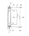
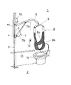
次に、本発明の実施の形態を図1に基づいて説明する。なお、図8及び図9と同一の部材には同一の符号を付す。図1において、符号21で示すものは本発明に係る介護用リフト装置である。介護用リフト装置21の支柱3は、室2の壁際に立設されている。この支柱3の適宜高さの位置にはブラケット4が固定されており、このブラケット4には偏平な枠部材22の一側22aが水平方向に回動自在に取り付けられている。枠部材22は、略四辺形に形成されたもので、縦が略48cm、横が略18cm、枠部分の厚みが略20mmのものである。枠部材22は、前記長辺側をブラケット4に取り付けている。
【0022】
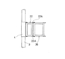
枠部材22の一側22aは管状体であるパイプ材によって形成されており、このパイプ材の上部及び下部に、図2に示すように、ベアリング23,23のアウタレースを嵌合する。また、ベアリング23,23のインナレースにはねじ手段を設ける。すなわち、上部及び下部に嵌合させたベアリング23,23にはボルト24を取り付ける。そして、このボルト24を装着した枠部材22をブラケット4の上下端の突部4A,4A間に介装させ、上下部のボルト24にナット25を螺合させて枠部材22を回動自在に保持する。
【0023】
上記枠部材22のブラケット4への取り付けを詳述する。先ず、枠部材22の一側22aのパイプ材(外径略34mm、内径略27mm、肉厚略3.5mm)の上下端部の内周を略1mm(奥行はベアリング23の厚さ分)程削って拡径し、拡径した部分にベアリング(外径略28mm、)23,23を嵌合させる。ベアリング23,23には、軸部が外部に突出するようにボルト(頭部径19mm)24が挿通されている(固定されていない)。そして、ボルト24の先端部が突出しないようにボルト24をパイプ材の内部に押し込めた状態で保持して、パイプ材をブラケット4の上下の突部4A,4A間に介装させる。
【0024】
上部のボルト24がブラケット4の突部4Aの孔に対応したらボルト24の軸部を突部4Aを通して外に引き出す。引出したら、パイプ材の外周部からボルト24の頭部に先端が食込刃になったねじ部材(長さ8mm程度、図示なし)をねじ込んで、ボルト24の落下を防止すると共に、ボルト24の廻り止めを行い、その後、ボルト24の軸部にナット25を螺合して締め付ける。
下部のボルト24は、パイプ材をブラケット4の下部の突部4Aに載置した際、軸部はその自重で突部4Aの孔を通して下側に突出するので、パイプ材の外周部からボルト24の頭部に上記と同じねじ部材をねじ込んでボルト24の廻り止めを行う。その後、ボルト24にナット25を螺合させて締め付け、枠部材22を回動自在に保持する。
【0025】
また、枠部材22の他側22bには、支持ブラケット26の上下端部が回動自在に取り付けられている。この支持ブラケット26の枠部材22への取り付けを、図3に基づいて説明する。支持ブラケット26も上記枠部材22の一側22aと同様に、管状体であるパイプ材で形成されているので、その取り付け方は上記枠部材22と同じである。すなわち、支持ブラケット26の上下端部の内周を削って拡径し、この拡径部分にボルト24を挿通させたベアリング23,23を嵌合し、このようにした支持ブラケット26を枠部材22の上下端に突出した軸受片22A,22Aの間に介装させ、軸受片22A,22Aの孔よりボルト24を突出させると共に、ボルト24の頭部を上記と同様のねじ部材で固定し、固定したボルト24にナット25を螺合させ支持ブラケット26を回動自在に保持する。
【0026】
なお、上記した枠部材22の支柱3のブラケット4への取り付けにおいて、ベアリング23,23にボルト24を挿通させたが、このようにせず、枠部材22のパイプ材の上部に嵌合させたベアリング23には内側から外側に突出するようにボルト24を取り付け、下部に嵌合させたベアリング23の内側に位置する部位にはナット25を取り付け、この状態の枠部材22を支柱3のブラケット4の上下の突部4A,4A間に介装し、上部のボルト24にはナット25を、下部のナット25にはボルト24を夫々螺合させて枠部材を回動自在に保持してもよい。なお、ボルト24、ナット25のベアリング23への取り付けは、溶接でも良いし、パイプ材から食込刃付きのねじ部材をねじ込んでも良い。さらに、枠部材22のパイプ材の径がベアリング23より大きい場合における、枠部材22へのベアリング23,23の取り付けは、溶接、鋲着、食込刃付きねじ部材等いずれでも良い。また、支持ブラケット26の枠部材22の軸受片22Aへの取り付けにおいても、上記と同様な取り付けをすることが可能である。この場合、構成は同じなので説明は省略する。
【0027】
そして、上記支持ブラケット26の外周の上下端部には、軸受片27が夫々突設されている。上部の軸受片27には、湾曲状のアーム6の基端部が上下方向に回動自在に取り付けられている。このアーム6の略中央部と、支持ブラケット26の下部の軸受片27との間にはアーム6を昇降させるための駆動手段7が介装されている。駆動手段7は伸縮自在のピストンロッド7aと、ケーシング7bとを備えており、その両端において回動するように介装されている。
【0028】
駆動手段7はケーシング7bの内部にモータ(図示なし)と、ピストンロッド7aと、ピストンロッド7aの内側に一体に設けたボールねじ(図示なし)と、このボールねじ及びモータの駆動軸を連結するウォームギヤ(図示なし)とを収容したもので、モータを駆動することによって、ウォームギヤを介してボールねじが回転してピストンロッド7aが伸長、短縮する公知のものである。
【0029】
さらに、駆動手段7を制御する制御手段であるコントローラ10が支柱3の上部に取り付けられている。このコントローラ10と、駆動手段7のモータとはケーブル11によって接続されている。さらに、コントローラ10にはモータを作動させるハンドスイッチ12が接続されている。
【0030】
また、上記アーム6の先端部には、被介護者Hの身体を下方より保持する布製の帯体8を懸架したハンガ9が吊下されている。帯体8は、被介護者Hの身体を背中から両腋にかけて支持する上部用帯体8a及び、臀部または大腿部を支持する下部用帯体8bの二本のもので構成されている。
【0031】
このような介護用リフト装置21の支柱3は、複数本の保持棒28により室2の床、壁面、天井に堅固に保持されている。支柱3と保持棒28及び、保持棒28同士は、図4乃至図6に示す形状の継手部材29により縦横に連結されている。
【0032】
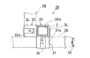
図4乃至図6は、継手部材29の一例を示したものである。この図4及び図5の継手部材29は角筒状の支柱3と、角筒状の保持棒28との交叉部位を締結するものである。この継手部材29は、支柱3を保持する筒部30と、筒部30の隣接する二面に保持棒28を保持する筒部31,32とが直交する状態で、溶着してなるものである。この場合、筒部30の面部30a,筒部31,32の各面部31a,32aの巾は同じ寸法にしてあり、筒部30の軸方向の長さは筒部31,32よりも長く形成されいる。図4及び図5は、支柱3が床面33上に立設された状態における平面図と正面図を示している。
【0033】
継手部材29の筒部30及び筒部31,32に支柱3及び二本の保持棒28を夫々挿通した場合は、L字形の補強板34を装着して、その上から食込刃付きのねじ部材(図示なし)を螺合させて、支柱3及び保持棒28を固定する。
補強板34を設けるのは、筒部30,31,32に食込刃付きのねじ部材を螺合させて、支柱3及び保持棒28を固定した場合、筒部30,31,32の板厚部分にできるねじ山だけでは、ねじ山の数が少なく締付時の強度が十分に得られないからである。このような補強板34を設けることによって、ねじ山数が多くなり強度が向上するようになる。
【0034】
図面では床面付近の構成を示したが、支柱3を一本立設する場合は、天井の近くでは保持棒28の両端は、四方の壁に夫々当接するように組み立て、支柱3の下部にあっては少なくとも対向する壁に一本の保持棒28の両端が接するように組み立てする必要がある。図4において、符号35で示すものは、保持棒28と壁との間の距離を調整し、保持棒28をつっ張らせて、保持するためのアジャストボルトである。
【0035】
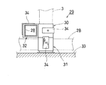
図6に示すものは、支柱3の筒部30の隣接する二面の上下位置に、保持棒28を保持する筒部31,32を直交する状態で溶着させたものである。この継手部材29の場合、保持棒28を筒部31,32に挿通させても、保持棒28は互いに干渉することがないので、支柱3を強く保持することができる。なお、図6、及び図4、図5は、支柱3の筒部30を保持棒28の筒部31,32よりも長く形成したが、筒部30の長さと、筒部31,32の長さとを同じにしてもよい。
【0036】
このように継手部材29を使用して保持棒28を締結したので、支柱3と保持棒28、または、保持棒28同士を容易に、かつ、強度を持たせて固定することができる。これにより、従来行っていた床や壁に孔をあけて、ボルトやビスをねじ込んだり、また、釘を打ち込んだりする作業を省略することができる。したがって、支柱3や保持棒28を固定する打込固定式のものに比べて床や壁に傷を付けることはない。
【0037】
次に、本発明の実施の形態の作用を説明する。上記説明した介護用リフト装置21を使用にして、被介護者Hをベッド等より離れた位置、または、障害物が途中にある車椅子に移動させるような場合、介護用リフト装置21のハンドスイッチ12を入れて、駆動手段7を作動させてピストンロッド7aを短縮させ、アーム6を下方向に回動させて、ハンガ9及び帯体8を被介護者Hの近くの適宜位置にまで下降させる。そして、図1に示すように、帯体8の上部用帯体8aを被介護者Hの身体の背中から腋下に回して上半身を支え、さらに、下部用帯体8bで被介護者Hの身体の腰より下を支えるように帯体8を装着する。
【0038】
このようにして被介護者Hの身体を帯体8で支持したら、ハンドスイッチ12を入れて駆動手段7のピストンロッド7aを伸長させて、アーム6の先端部を上方向に回動させて、ハンガ9と共に被介護者Hの身体を上昇させる。その後、被介護者Hの体を押すことによって、アーム6を支持ブラケット26及び枠部材22を中心に水平方向に回動させてハンガ9と共に、被介護者Hの身体を旋回移動させる。
【0039】
このとき枠部材22の旋回方向に障害物があって、障害物と枠部材22とが干渉し、枠部材22の旋回が阻止されても、枠部材22の他側22bにアーム6を保持した支持ブラケット26が回動可能に取り付けられているので、アーム6は支持ブラケット26を中心に旋回し、ハンガ9及び被介護者Hを障害物を回り込んで移動することができる。
【0040】
被介護者Hが車椅子の上方に移動したら、ハンドスイッチ12の下降ボタンを押して被介護者Hを下降させ車椅子に載せる。このように介護用リフト装置21に枠部材22を設けたことにより、アーム6の旋回可動域が大きくなり、被介護者Hを車椅子に容易に載せることができる。被介護者Hを車椅子に載せたら、帯体8を被介護者Hの身体より外し帯体8のみを上方に吊り上げる。
【0041】
なお、上記介護用リフト装置21は枠部材22を一個支柱3に組み付けたものを説明したが、アーム6の旋回可動域をさらに大きく広げる場合は、図7に示すように、枠部材22に、さらにもう一個の枠部材36を組み付ける形態を採用する。このように枠部材22の追加組付けを行えば、被介護者Hの身体を確実に障害物を越えて移動させることができる。組み付ける枠部材36は、縦が略48cm、横が略29cm、厚みが略20mmの偏平をした略四辺形(長方形)をしたものである。
【0042】
【発明の効果】
請求項1記載の発明は上記構成からなるものであるから、水平方向に回動自在の枠部材と、該枠部材に枢着した支持ブラケットの上部に上方に向かって延びるアームとによって、ハンガの旋回可動域を大きくすることができる。これによって、枠部材の旋回方向に障害物があっても、ハンガを当該位置から障害物を越えて反対側に旋回進入させることができる。これによって、被介護者の移動範囲を広くすることができる。また、扁平で、かつ、略四辺形(長方形)の枠部材の長辺側一端を水平方向に回動自在に支柱に取り付けたので、重量に対する強度を向上させることができる。
【0043】
また、請求項2記載の発明にあっては、枠部材を複数個連結したので、ハンガの旋回可動域をさらに大きく、かつ、変化あるものとすることができ、被介護者の移動を容易にすることができる。また、各枠部材を扁平、かつ、四辺形(長方形)に形成したので、各枠部材が軽量となり、強度を高くすることができる。
【0044】
さらに、請求項3記載の発明にあっては、扁平な枠部材の長辺側両端のうち少なくとも一端を管状体にし、その上下部に軸受を嵌合させたので、被介護者を旋回させる際、枠部材を円滑に回動させることができる。
【図面の簡単な説明】
【図1】本発明の実施例の形態を示す模式図である。
【図2】図1のものの枠部材の取り付けを示す一部断面正面図である。
【図3】図1のものの支持ブラケットの取り付けを示す一部断面正面図である。
【図4】図1に示す継手部材の平面図である。
【図5】図4に示すものの正面図である。
【図6】図5に示す継手部材の他の例の正面図である。
【図7】図1に示す枠部材を二つ繋げたところを示す模式図である。
【図8】従来の介護用リフト装置の模式図である。
【図9】従来の他の介護用リフト装置のアーム部分の模式図である。
【符号の説明】
2 室
3 支柱
4 ブラケット
6 アーム
7 駆動手段
8 帯体
9 ハンガ
10 コントローラ
21 介護用リフト装置
22 枠部材
22a 一側
22b 他側
26 支持ブラケット
28 保持棒
29 継手部材
36 枠部材
H 被介護者[0001]
BACKGROUND OF THE INVENTION
The present invention relates to a lift device for care that can lift a person who has a weak body such as a physically handicapped person or a long-term care person and needs care (hereinafter referred to as a care receiver) and moves it from a bed or the like to a wheelchair. It is about.
[0002]
[Prior art]
Many types of devices have been proposed as this type of care lifting device. FIG. 8 shows an example. This
[0003]
On the
[0004]
When the care receiver's body is moved from, for example, a wheelchair onto the
[0005]
Next, the raising button of the
[0006]
The
[0007]
Therefore, if there are obstacles (walls, steps, etc.) in the swivel movable range of the
[0008]
In order to solve this problem, a nursing care lift device 15 (only the main part is shown) 15 as shown in FIG. 9 has been proposed. The
[0009]
In this way, even if the
[0010]
[Problems to be solved by the invention]
However, since the shape of the
[0011]
Further, in the conventional care lift device, when fixing the
If a screw hole is provided, the floor and wall will be damaged, and in the case of a rental house, when moving, the hole must be closed and the floor or wall must be returned to the original state without any damage. The work for this is complicated, and if it asks a contractor, it will become so expensive, and the problem that the attachment of a care lift device must be abandoned will occur eventually.
[0012]
The present invention has been made to solve the above-described conventional problems, and an arm that raises or lowers the body of a cared person is attached to a support via a frame member, thereby increasing the swivel movable range of the arm. The cared person's body can be moved to a position beyond obstacles such as walls and pillars, the strength of the bracket etc. can be improved, and the pillars and holding rods can be moved without damaging the wall or floor. An object of the present invention is to provide a nursing care lift device that is assembled, further avoids the complexity of hole closing work, and reduces costs.
[0013]
[Means for Solving the Problems]
In order to solve the above-mentioned problem, the invention described in
[0014]
In the invention described in
[0015]
Furthermore, the invention described in
[0017]
In the first aspect of the present invention, since the above-described configuration is adopted, the swivel movable range of the arm becomes large, and even if the walls, columns, etc. interfere with each other and the swivel of the arm is prevented as in the prior art. It becomes possible to move the arm, hanger, and the like to a position beyond an obstacle such as a wall or a pillar. In addition, since the driving means is interposed between the arm and the support bracket, the hanger suspended from the arm can be raised and lowered, and the body of the cared person held by the belt can be raised and moved. At the same time, it can be lowered to a wheelchair or the like. Moreover, since it attached to the support | pillar rotatably in the state which stood the frame member, the intensity | strength at the time of holding a care receiver improves.
[0018]
In the invention described in
[0019]
In the invention according to
[0021]
DETAILED DESCRIPTION OF THE INVENTION
Next, an embodiment of the present invention will be described with reference to FIG. In addition, the same code | symbol is attached | subjected to the member same as FIG.8 and FIG.9. In FIG. 1, what is shown by the code |
[0022]
One side 22a of the
[0023]
The attachment of the
[0024]
When the
When the pipe material is placed on the
[0025]
The upper and lower ends of the
[0026]
In the above-described attachment of the
[0027]
And the bearing
[0028]
The drive means 7 connects a motor (not shown), a
[0029]
Further, a
[0030]
Further, a
[0031]
The
[0032]
4 to 6 show an example of the
[0033]
When the
The reinforcing
[0034]
In the drawing, the configuration near the floor surface is shown. However, when one
[0035]
6 shows that
[0036]
Since the holding
[0037]
Next, the operation of the embodiment of the present invention will be described. When the
[0038]
When the body of the care recipient H is supported by the
[0039]
At this time, even if there is an obstacle in the turning direction of the
[0040]
When the cared person H moves above the wheelchair, the lowering button of the
[0041]
In addition, although the said
[0042]
【The invention's effect】
Since the invention according to
[0043]
Further, in the invention of
[0044]
Furthermore, in the invention according to
[Brief description of the drawings]
FIG. 1 is a schematic view showing an embodiment of the present invention.
FIG. 2 is a partial cross-sectional front view showing attachment of the frame member of FIG. 1;
FIG. 3 is a partial cross-sectional front view showing attachment of the support bracket of FIG. 1;
4 is a plan view of the joint member shown in FIG. 1. FIG.
FIG. 5 is a front view of what is shown in FIG. 4;
6 is a front view of another example of the joint member shown in FIG. 5. FIG.
7 is a schematic view showing a state where two frame members shown in FIG. 1 are connected. FIG.
FIG. 8 is a schematic view of a conventional care lift device.
FIG. 9 is a schematic view of an arm portion of another conventional lift device for nursing care.
[Explanation of symbols]
2
Claims (3)
該ブラケットに、長方形の扁平な枠部材の長辺側一端を水平方向に回動自在に取り付け、
該枠部材の長辺側他端に水平方向に回動自在の支持ブラケットを取り付け、
該支持部ブラケットの上部に略上方に延びるアームの基端部を上下方向に回動自在に取り付け、
該アームの略中間部と前記支持ブラケットの下部との間に、前記アームをその基端部を支点に上下方向に回動させるための駆動手段を介装し、
前記アームの先端部に被介護者を下方より保持するための帯体を懸架したハンガを吊下すると共に、前記駆動手段を制御する制御手段を設けたことを特徴とする介護用リフト装置。Brackets are provided at appropriate positions on the columns that are erected indoors.
A long side end of a rectangular flat frame member is attached to the bracket so as to be rotatable in the horizontal direction.
Mounting the support bracket rotatably horizontally long side other end of the frame member,
A base end portion of an arm extending substantially upward is attached to the upper portion of the support bracket so as to be rotatable in the vertical direction.
Between the lower of the support bracket and the substantially middle portion of the arm, interposed the drive means for rotating the vertical direction the arms to pivot the proximal end portion,
A lifting device for nursing care, comprising a hanger suspended from a belt for holding a care receiver from below at the tip of the arm, and a control means for controlling the driving means.
該ブラケットに、長方形の扁平な枠部材の長辺側一端を水平方向に回動自在に取り付け、
該枠部材を、隣接する長辺側端部が互いに水平方向に回動自在となるように水平方向に沿って複数個連結して、
該各枠部材のうち最も先端側に位置する枠部材の長辺側他端に水平方向に回動自在の支持ブラケットを取り付け、
該支持部ブラケットの上部に略上方に延びるアームの基端部を上下方向に回動自在に取り付け、
該アームの略中間部と前記支持ブラケットの下部との間に、前記アームをその基端部を支点に上下方向に回動させるための駆動手段を介装し、
前記アームの先端部に被介護者を下方より保持するための帯体を懸架したハンガを吊下すると共に、前記駆動手段を制御する制御手段を設けたことを特徴とする介護用リフト装置。 Brackets are provided at appropriate positions on the columns that are erected indoors.
A long side end of a rectangular flat frame member is attached to the bracket so as to be rotatable in the horizontal direction.
A plurality of the frame members are connected along the horizontal direction so that adjacent long side end portions are rotatable in the horizontal direction,
A support bracket that is rotatable in the horizontal direction is attached to the other end of the long side of the frame member that is located on the most distal side among the frame members,
A base end portion of an arm extending substantially upward is attached to the upper portion of the support bracket so as to be rotatable in the vertical direction.
Between the substantially intermediate part of the arm and the lower part of the support bracket, a driving means for rotating the arm in the vertical direction with its base end as a fulcrum is interposed,
A lifting device for nursing care , comprising a hanger suspended from a belt for holding a care receiver from below at the tip of the arm, and a control means for controlling the driving means .
Priority Applications (1)
| Application Number | Priority Date | Filing Date | Title |
|---|---|---|---|
| JP24583799A JP4432155B2 (en) | 1999-08-31 | 1999-08-31 | Care lift device |
Applications Claiming Priority (1)
| Application Number | Priority Date | Filing Date | Title |
|---|---|---|---|
| JP24583799A JP4432155B2 (en) | 1999-08-31 | 1999-08-31 | Care lift device |
Publications (2)
| Publication Number | Publication Date |
|---|---|
| JP2001061907A JP2001061907A (en) | 2001-03-13 |
| JP4432155B2 true JP4432155B2 (en) | 2010-03-17 |
Family
ID=17139598
Family Applications (1)
| Application Number | Title | Priority Date | Filing Date |
|---|---|---|---|
| JP24583799A Expired - Fee Related JP4432155B2 (en) | 1999-08-31 | 1999-08-31 | Care lift device |
Country Status (1)
| Country | Link |
|---|---|
| JP (1) | JP4432155B2 (en) |
Cited By (1)
| Publication number | Priority date | Publication date | Assignee | Title |
|---|---|---|---|---|
| CN109893779A (en) * | 2019-04-08 | 2019-06-18 | 山东大学 | A kind of movable bed suitable for radiotherapy department |
Families Citing this family (3)
| Publication number | Priority date | Publication date | Assignee | Title |
|---|---|---|---|---|
| WO2006025751A1 (en) * | 2004-09-02 | 2006-03-09 | Cunningplanz Limited | A mobile support for a hoist |
| CN110960372B (en) * | 2020-01-08 | 2024-04-26 | 淄博科创医疗仪器有限公司 | Lifting type bedridden patient carrying robot |
| CN114699269B (en) * | 2022-03-24 | 2023-10-10 | 郑州大学第二附属医院 | Medical common surgical treatment table |
-
1999
- 1999-08-31 JP JP24583799A patent/JP4432155B2/en not_active Expired - Fee Related
Cited By (1)
| Publication number | Priority date | Publication date | Assignee | Title |
|---|---|---|---|---|
| CN109893779A (en) * | 2019-04-08 | 2019-06-18 | 山东大学 | A kind of movable bed suitable for radiotherapy department |
Also Published As
| Publication number | Publication date |
|---|---|
| JP2001061907A (en) | 2001-03-13 |
Similar Documents
| Publication | Publication Date | Title |
|---|---|---|
| US5146638A (en) | Bath | |
| US4003479A (en) | Hoist and transporting apparatus | |
| AU725673B2 (en) | Invalid hoists | |
| US6964070B2 (en) | Patient lifting apparatus | |
| JPH0686791A (en) | Hoist for physically handicapped person | |
| JP4432155B2 (en) | Care lift device | |
| US5875501A (en) | Patient lift | |
| US2617117A (en) | Electrically operated invalid's bed | |
| US6256807B1 (en) | Bath lift | |
| JP3022293B2 (en) | Nursing lift | |
| WO2008075982A2 (en) | Leg lifting apparatus | |
| JP2590767B2 (en) | Electric lifting type nursing care device | |
| JP4970801B2 (en) | Bath lift device | |
| JPH0646369Y2 (en) | Assembled floor lift bed | |
| JP2001314458A (en) | Traveling nursing lift with rotary supporting post | |
| JPH0947476A (en) | Lift device | |
| JP2000300626A (en) | Auxiliary lift device | |
| JP3020929B1 (en) | Emergency lowering mechanism for electric care lift | |
| JPH09580A (en) | Medical care lift device | |
| JP2001029175A (en) | Electric low-floor type elevatable bed | |
| JP2002301129A (en) | Bathing care auxiliary | |
| CA2167852A1 (en) | Patient lift modification | |
| JP3188420B2 (en) | Nursing lifts and nursing beds | |
| JP3215630B2 (en) | Assisted bathing equipment | |
| JP3658022B2 (en) | Bathing equipment |
Legal Events
| Date | Code | Title | Description |
|---|---|---|---|
| A621 | Written request for application examination |
Free format text: JAPANESE INTERMEDIATE CODE: A621 Effective date: 20060830 |
|
| A977 | Report on retrieval |
Free format text: JAPANESE INTERMEDIATE CODE: A971007 Effective date: 20090305 |
|
| A131 | Notification of reasons for refusal |
Free format text: JAPANESE INTERMEDIATE CODE: A131 Effective date: 20090610 |
|
| A521 | Written amendment |
Free format text: JAPANESE INTERMEDIATE CODE: A523 Effective date: 20090805 |
|
| TRDD | Decision of grant or rejection written | ||
| A01 | Written decision to grant a patent or to grant a registration (utility model) |
Free format text: JAPANESE INTERMEDIATE CODE: A01 Effective date: 20091202 |
|
| A01 | Written decision to grant a patent or to grant a registration (utility model) |
Free format text: JAPANESE INTERMEDIATE CODE: A01 |
|
| A61 | First payment of annual fees (during grant procedure) |
Free format text: JAPANESE INTERMEDIATE CODE: A61 Effective date: 20091214 |
|
| R150 | Certificate of patent or registration of utility model |
Free format text: JAPANESE INTERMEDIATE CODE: R150 |
|
| FPAY | Renewal fee payment (event date is renewal date of database) |
Free format text: PAYMENT UNTIL: 20130108 Year of fee payment: 3 |
|
| R250 | Receipt of annual fees |
Free format text: JAPANESE INTERMEDIATE CODE: R250 |
|
| R250 | Receipt of annual fees |
Free format text: JAPANESE INTERMEDIATE CODE: R250 |
|
| R250 | Receipt of annual fees |
Free format text: JAPANESE INTERMEDIATE CODE: R250 |
|
| R250 | Receipt of annual fees |
Free format text: JAPANESE INTERMEDIATE CODE: R250 |
|
| LAPS | Cancellation because of no payment of annual fees |