EP0448816B1 - Apparatus for determining volatile substances in a liquid - Google Patents
Apparatus for determining volatile substances in a liquid Download PDFInfo
- Publication number
- EP0448816B1 EP0448816B1 EP90124696A EP90124696A EP0448816B1 EP 0448816 B1 EP0448816 B1 EP 0448816B1 EP 90124696 A EP90124696 A EP 90124696A EP 90124696 A EP90124696 A EP 90124696A EP 0448816 B1 EP0448816 B1 EP 0448816B1
- Authority
- EP
- European Patent Office
- Prior art keywords
- gas
- tube
- liquid
- flow
- water
- Prior art date
- Legal status (The legal status is an assumption and is not a legal conclusion. Google has not performed a legal analysis and makes no representation as to the accuracy of the status listed.)
- Expired - Lifetime
Links
Images
Classifications
-
- G—PHYSICS
- G01—MEASURING; TESTING
- G01N—INVESTIGATING OR ANALYSING MATERIALS BY DETERMINING THEIR CHEMICAL OR PHYSICAL PROPERTIES
- G01N1/00—Sampling; Preparing specimens for investigation
- G01N1/28—Preparing specimens for investigation including physical details of (bio-)chemical methods covered elsewhere, e.g. G01N33/50, C12Q
- G01N1/40—Concentrating samples
- G01N1/4055—Concentrating samples by solubility techniques
- G01N2001/4066—Concentrating samples by solubility techniques using difference of solubility between liquid and gas, e.g. bubbling, scrubbing or sparging
-
- G—PHYSICS
- G01—MEASURING; TESTING
- G01N—INVESTIGATING OR ANALYSING MATERIALS BY DETERMINING THEIR CHEMICAL OR PHYSICAL PROPERTIES
- G01N33/00—Investigating or analysing materials by specific methods not covered by groups G01N1/00 - G01N31/00
- G01N33/18—Water
Definitions
- the invention relates to a device for detecting volatile constituents (gases or vapors) in water.
- the water to be analyzed is continuously passed through a phase exchanger (stripper), where the volatile constituents are discharged with a carrier gas stream.
- the gas stream enriched with the substance is then fed to an analysis device which detects this substance.
- a typical and therefore frequently occurring problem is the timely detection of organic substances, such as aromatic and aliphatic hydrocarbons, Ethers, esters, alcohols, ketones, halogenated hydrocarbons and other analytical methods which can measure the organic load in water are known.
- Automatic devices measure, for example, the TC value (total carbon) by thermally / catalytically burning a small wastewater sample to CO 2 in a pyrolysis furnace. The CO 2 concentration is then recorded in an infrared analyzer (1).
- the aim of this invention is to simplify such a measuring device and to improve the response behavior by combining a very fast analysis device with an effective stripping device.
- the stripping device the volatile organic substances are converted from the aqueous phase into the gas phase.
- the headspace method uses the equilibrium ratio of the concentrations of organic substances in water and the gas space above. This method is often used in combination with a gas chromatograph, since only small amounts of the gas space to be analyzed are available and are only required for this analyzer.
- a closed carrier gas circuit is used to completely deplete the organic components in the water and either feed the gas stream directly to a gas chromatograph (2), or to enrich the organic substances in only a small amount in a cold trap or on an adsorber and then concentrate it by evaporation or desorption Measure gas in the gas chromatograph (3/4).
- the methods just mentioned are exclusively laboratory methods and only allow discontinuous measurements.
- a stripping method for the continuous monitoring of water for volatile halogenated hydrocarbons, a stripping method is known in which air is bubbled into the water in a flow transmitter with a siphon through a tube with holes.
- the flow transmitter is in the water flow to be examined.
- the stripper air bubbles in excess through the holes in the water and enriches itself with the organic substances.
- Part of the gas is fed to an analyzer for the determination of the organic substances.
- the aim of the present invention is to improve the spripping procedure in connection with a gas analysis device, for example when measuring organic ingredients in water with regard to rapid material exchange with a direct supply of the current stripping gas to the analyzer, the stripping process not being impaired by the fill level of the flow armature or by a high flow velocity in the apparatus.
- a detector system is known from US 4546640, in which strip gas is introduced into a quasi extraction tube below the filling level thereof.
- the stripping gas is introduced into the liquid regardless of flow, so that the stripping process is not optimal.
- US 3942792 a generic arrangement is known, in which a targeted flow is generated in a sampling tube.
- the strip gas is introduced in a flow-guided manner within this flow.
- the stripping process is not optimized because the liquid flows back via a siphon-like arrangement and a part of the stripping gas can be carried away unused by the flowing liquid during this procedure.
- the invention is therefore based on the object of improving the stripping procedure.
- This object is achieved, starting from a gas analyzer with a sampling tube leading to the liquid, in that the sampling tube is connected to an immersion tube projecting into the liquid, which surrounds a porous distributor body connected to the gas supply tube and the liquid flows laterally against it.
- the carrier gas passes through the distributor body in the form of finely divided gas bubbles into the liquid volume enclosed by the dip tube and, after bubbling through, flows completely upwards. A partial flow is continuously conveyed to the analysis device for determining the measuring components.
- the immersion tube thus encloses the liquid volume bubbled through by the carrier gas, so that a defined volume is available in the liquid for the mass transfer (stripping process).
- the distributor body consists of a porous plate arranged at an angle to the direction of flow.
- the lower end of the immersion tube is chamfered on the side facing the flowing liquid and extends with its part arranged inside the flow tube over at least two thirds of the flow tube diameter. This ensures that even with a low fill level in the flow tube, an ongoing exchange with newly flowing liquid is possible and, at the same time, contamination by solid particles in the water can be prevented as a result of the turbulence occurring in the dip tube.
- the angle of attack of the porous distributor plate is advantageously 30 ° -85 °, preferably 50 ° -70 °.
- the distance between the inclined distributor plate and the inclined underside of the dip tube is dimensioned such that the volume of liquid in the dip tube is small and thus a quick exchange takes place. At the same time, this ensures that the carrier gas can rise relatively quickly within the sampling tube.
- the level of the liquid level in the immersion tube is essentially determined by the level in the flow tube if no back pressure has to be overcome on the outflow side.
- the distance a between the lower end of the distributor body and the lower end of the sampling tube is advantageously 0.5 cm to 1.5 cm.
- the immersion tube is expediently provided with an overflow.
- An embodiment has proven particularly effective, which consists of a combination of the stripping device described with a flame ionization detector (FID), at the gas-side inlet of which negative pressure is maintained, so that the stripping gas is sucked in by the FID.
- FID flame ionization detector
- the device described allows continuous monitoring of vaporizable inorganic and organic substances in water, for example of solvents.
- a flame ionization detector FID
- the response time is less than 10 s.
- the detection limit depends on the substance and depends on the volatility and solubility in water.
- the hydrophobic hydrocarbons and the ecologically questionable, chlorinated hydrocarbons can be detected particularly sensitively.
- the detection limit for these substance groups is below 10 ⁇ l / l.
- the combination stripper / FID is therefore also a TOC device with regard to detection sensitivity think. Hardly evaporable and salt-like compounds cannot be detected.
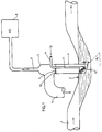
- the liquid to be examined flows here from left to right through a flow tube 1, which forms a siphon 2.
- a dip tube 3 is installed on the siphon 2 perpendicular to the flow tube 1.
- the lower end of the dip tube 3 is chamfered such that the entry surface of the dip tube faces the flow.
- the length of the obliquely flattened immersion tube is dimensioned so that even with a low fill level in the flow tube 1 a quick exchange with new inflowing water is possible and, at the same time, contamination by solids in the water is prevented as a result of the turbulence occurring in the immersion tube.
- the gas analyzer here is a flame ionization detector (FID).
- the FID is operated at its inlet with negative pressure, so that the sample gas component is sucked in through the sampling tube 9.
- An FID of this type is described in DE-PS 29 32 436.
- a diaphragm 10 serving as a water barrier is provided with an opening of 2 to 3 mm in diameter (opening 7).
- a gas supply pipe 11 with an inclined porous distributor plate 12 is arranged inside the immersion pipe 3.
- the porous distributor plate can consist of a glass frit or a sintered plate or of a wooden body. Alternatively, a fine perforated screen can be used.
- the angle of attack ⁇ of the distributor plate 12 should be at least 30 °. A range between 50 ° and 70 ° has proven particularly useful.
- the outlet surface of the distributor body faces the flow; i.e. the normal on the distributor surface has a component opposite to the flow.
- the inclination of the distributor plate 12 has proven to be particularly favorable, since finely divided, non-coalescing gas bubbles are formed in this way, which result in intensive stripping of the volatile components containing the liquid stream (water).
- the distributor plate 12 is located just above the beveled dip tube end 4 and below the liquid level in the dip tube 3, which is predetermined in normal operation by the liquid level in the flow tube siphon 2.
- the distance a between the lower end of the distributor plate 12 and the lower end of the dip tube 3 is 0.5 to 1.5 cm. Consequently there is a spatially limited, quickly exchangeable water volume available for the stripping process. This is essential for a fast response time of the FID 8 when the concentration of the sample gas component changes.
- Hydrogen-free atmospheric air is normally used as the carrier gas.
- the use of other gases such as nitrogen, carbon dioxide or noble gases is also conceivable.
- the carrier gas 13 reaches the distributor plate 12 via the feed pipe 11 and rises there in the form of fine gas bubbles, enriched with the volatile constituents of the waste water stream.
- the gas mixture then flows through the opening 7 of the water barrier 10 into the immersion tube head 5. A part of the gas mixture is sucked in by the FID 8 through the extraction tube 9, while the excess portion flows out through the overflow tube 6.
- wastewater flows between 30 and 300 l per hour can be monitored online.
- Carrier gas flows between 30 and 100 l per hour are used.
- Waste water flow rate 150 l per hour
- Carrier gas flow (air) 100 l per hour
- the measuring component to be examined consisted of chlorobenzene and dichloromethane vapors. With a substance concentration of 50 ⁇ l / l dichloromethane, an organic carbon amount of 320 mg / m 3 was measured in the FID. The detection limit was 0.4 ⁇ l / l.
Abstract
Description
Die Erfindung betrifft eine Vorrichtung zur Erfassung von flüchtigen Inhaltsstoffen (Gase bzw. Dämpfe) in Wasser. Hierbei wird das zu analysierende Wasser kontinuierlich durch einen Phasentauscher (Stripper) geleitet, wo die flüchtigen Bestandteile mit einem Trägergasstrom ausgetragen werden. Der mit der Substanz angereicherte Gasstrom wird dann einem Analysengerät zugeführt, welches diese Substanz nachweist.The invention relates to a device for detecting volatile constituents (gases or vapors) in water. Here, the water to be analyzed is continuously passed through a phase exchanger (stripper), where the volatile constituents are discharged with a carrier gas stream. The gas stream enriched with the substance is then fed to an analysis device which detects this substance.
Zur rechtzeitigen Erkennung plötzlich und unbeabsichtigt aufgetretener Emission von wassergefährdenden Substanzen im Kühlwasser oder in Produktionsabwässern sind Analysenverfahren, die zumindest einen qualitativen Frühnachweis erbringen können, von großer Bedeutung.For timely detection of sudden and unintentional emissions of water-polluting substances in cooling water or in production wastewater, analytical methods that can provide at least qualitative early detection are of great importance.
Ein typisches und daher häufig auftretendes Problem ist die rechtzeitige Detektion von organischen Stoffen, wie z.B. aromatische und aliphatische Kohlenwasserstoffe, Ether, Ester, Alkohole, Ketone, Halogenkohlenwasserstoffe u.a. Analysenverfahren, die die organische Fracht in Wasser messen können, sind bekannt. Automatische Geräte messen z.B. den TC-Wert (Total Carbon), indem eine kleine Abwasserprobe in einem Pyrolyseofen thermisch/katalytisch zu CO2 verbrannt wird. Die CO2-Konzentration wird anschließend in einem Infrarot-Analysator erfaßt (1).A typical and therefore frequently occurring problem is the timely detection of organic substances, such as aromatic and aliphatic hydrocarbons, Ethers, esters, alcohols, ketones, halogenated hydrocarbons and other analytical methods which can measure the organic load in water are known. Automatic devices measure, for example, the TC value (total carbon) by thermally / catalytically burning a small wastewater sample to CO 2 in a pyrolysis furnace. The CO 2 concentration is then recorded in an infrared analyzer (1).
Es ist ferner bekannt, die organische Fracht über den chemischen Sauerstoffbedarf (CSB-Wert) zu bestimmen. Auch hierfür stehen kontinuierliche Meßverfahren zur on line-Analyse zur Verfügung.It is also known to determine the organic load via the chemical oxygen demand (COD value). Continuous measurement methods for on-line analysis are also available for this.
Nachteilig ist, daß diese Geräte eine recht aufwendige Analyseprozedur durchführen und daher technologisch aufwendig und wartungsintensiv sind. Hinzu kommt, daß die Ansprechzeiten im Bereich mehrerer Minuten liegen, so daß eine rasche Alarmgabe bei plötzlich auftretenden Leckagen nicht möglich ist.The disadvantage is that these devices perform a very complex analysis procedure and are therefore technologically complex and maintenance-intensive. In addition, the response times are in the range of several minutes, so that a rapid alarm in the event of sudden leaks is not possible.
Ziel dieser Erfindung ist eine Vereinfachung einer solchen Meßeinrichtung sowie eine Verbesserung des Ansprechverhaltens durch die Kombination eines sehr schnellen Analysengerätes mit einer wirkungsvollen Strippvorrichtung. In der Strippvorrichtung werden die flüchtigen organischen Substanzen von der wäßrigen Phase in die Gasphase überführt.The aim of this invention is to simplify such a measuring device and to improve the response behavior by combining a very fast analysis device with an effective stripping device. In the stripping device, the volatile organic substances are converted from the aqueous phase into the gas phase.
Es ist bekannt, die Überführung von organischen Bestandteilen in die Gasphase nach der Headspace-Methode oder durch Strippvorrichtungen vorzunehmen und den Gehalt an organischen Stoffen in dieser Gasphase zu bestimmen.It is known to convert organic components into the gas phase by the headspace method or by means of stripping devices and to determine the content of organic substances in this gas phase.
Bei der Headspace-Methode nützt man nach dem Henry'schen Gesetz das Gleichgewichtsverhältnis der Konzentrationen an organischen Stoffen in Wasser und dem darüber befindlichen Gasraum aus. Diese Methode wird häufig in Kombination mit einem Gaschromatographen verwendet, da nur geringe Mengen des zu analysierenden Gasraumes vorhanden sind und für diesen Analysator auch nur benötigt werden.According to Henry's law, the headspace method uses the equilibrium ratio of the concentrations of organic substances in water and the gas space above. This method is often used in combination with a gas chromatograph, since only small amounts of the gas space to be analyzed are available and are only required for this analyzer.
Bei den bekannten Strippeinrichtungen wird z.B. ein geschlossener Trägergaskreislauf benutzt, um die organischen Bestandteile im Wasser vollständig abzureichern und entweder den Gasstrom direkt einem Gaschromatographen zuzuführen (2), oder bei nur geringen Mengen die organischen Substanzen in einer Kühlfalle oder an einem Adsorber anzureichern und anschließend durch Verdampfen bzw. Desorbieren dieses aufkonzentrierte Gas im Gaschromatographen zu messen (3/4). Die eben genannten Methoden sind ausschließlich Labormethoden und ermöglichen nur eine diskontinuierliche Messung.In the known stripping devices e.g. a closed carrier gas circuit is used to completely deplete the organic components in the water and either feed the gas stream directly to a gas chromatograph (2), or to enrich the organic substances in only a small amount in a cold trap or on an adsorber and then concentrate it by evaporation or desorption Measure gas in the gas chromatograph (3/4). The methods just mentioned are exclusively laboratory methods and only allow discontinuous measurements.
Eine weitere Labormethode zur Bestimmung von Kohlenwasserstoffen in Wasser benutzt "in-situ" elektrochemisch erzeugten Wasserstoff als Strippgas mit anschließend gaschromatographischer Bestimmung der Kohlenwasserstoffe im Dampfraum der Probe (5/6).Another laboratory method for the determination of hydrocarbons in water uses "in-situ" electrochemically generated hydrogen as stripping gas with subsequent gas chromatographic determination of the hydrocarbons in the vapor space of the sample (5/6).
Zur kontinuierlichen Überwachung von Wasser auf leichtflüchtige Halogenkohlenwasserstoffe ist ein Strippverfahren bekannt, bei dem in einem Durchflußgeber mit Syphon durch ein Rohr mit Löchern Luft in das Wasser einperlt. Der Durchflußgeber befindet sich in dem zu untersuchenden Wasserstrom. Die Stripperluft perlt hierbei im Überschuß durch die Löcher in das Wasser und reichert sich dabei mit den organischen Stoffen an. Ein Teil des Gases wird einem Analysengerät zwecks Bestimmung der organischen Substanzen zugeführt.For the continuous monitoring of water for volatile halogenated hydrocarbons, a stripping method is known in which air is bubbled into the water in a flow transmitter with a siphon through a tube with holes. The flow transmitter is in the water flow to be examined. The stripper air bubbles in excess through the holes in the water and enriches itself with the organic substances. Part of the gas is fed to an analyzer for the determination of the organic substances.
Beim bisherigen Verfahren ist nachteilig, daß je nach der Durchflußgeschwindigkeit des Wassers und je nach dem Wasserstand in der Durchflußapparatur mehr oder weniger viel Strippgas vom Wasserstrom mitgerissen wird. Im ungünstigen Falle wird alles Gas mitgerissen, so daß kein Gas zur Analyse zur Verfügung steht. Nachteilig ist ebenfalls, daß bei Verstopfungen auf der Abflußseite Wasser über die Löcher in die Gasleitung und somit in den Gasanalysator gelangen kann. Letztendlich kann, in Abhängigkeit vom Wasserstand im Durchflußgeber, der Gasraum über dem Wasser sehr groß sein, so daß Gas vom Analysengerät gemessen wird, welches nicht mit der Gaszusammensetzung über der aktuellen Wasserprobe identisch ist. Dies bedeutet jedoch eine Verfälschung der Meßergebnisse.In the previous method, it is disadvantageous that, depending on the flow rate of the water and the water level in the flow apparatus, more or less stripping gas is entrained by the water flow. In the worst case, all gas is entrained so that no gas is available for analysis. Another disadvantage is that in the event of blockages on the outflow side, water can get through the holes in the gas line and thus into the gas analyzer. Ultimately, depending on the water level in the flow transmitter, the gas space above the water can be very large, so that gas is measured by the analyzer which is not identical to the gas composition above the current water sample. However, this means that the measurement results are falsified.
Ziel der vorliegenden Erfindung ist eine Verbesserung der Sprippingprozedur in Verbindung mit einem Gasanalysengerät z.B. bei der Messung von organischen Inhaltsstoffen in Wasser hinsichtlich eines raschen Stoffaustausches mit einer direkten Zuführung des aktuellen Strippgases zum Analysator, wobei der Strippvorgang nicht durch die Füllhöhe der Durchflußarmatur oder durch eine hohe Strömungsgeschwindigkeit in der Apparatur beeinträchtigt wird.The aim of the present invention is to improve the spripping procedure in connection with a gas analysis device, for example when measuring organic ingredients in water with regard to rapid material exchange with a direct supply of the current stripping gas to the analyzer, the stripping process not being impaired by the fill level of the flow armature or by a high flow velocity in the apparatus.
Weiterhin ist aus der US 4546640 ein Detektorsystem bekannt, bei welchem Strip Gas in ein quasi Entnahmerohr unterhalb der Füllhöhe desselben eingeleitet wird. Das Stripgas wird ohne Rücksicht auf Strömung in die Flüssigkeit eingeleitet, so daß der Strip-Vorgang nicht optimal ist. Aus der US 3942792 ist eine gattungsgemäße Anordnung bekannt, bei welcher in einem Entnahmerohr eine gezielte Strömung erzeugt wird. Innerhalb dieser Strömung wird das Strip-Gas quasi strömungsgeführt eingeleitet. Auch hierbei ist der Stripvorgang nicht optimiert, weil die Flüssigkeit über eine Siphonähnliche Anordnung wieder zurückfließt und ein Teil des Stripgases bei dieser Prozedur ungenutzt von der strömenden Flüssigkeit mitgerissen werden kann.Furthermore, a detector system is known from US 4546640, in which strip gas is introduced into a quasi extraction tube below the filling level thereof. The stripping gas is introduced into the liquid regardless of flow, so that the stripping process is not optimal. From US 3942792 a generic arrangement is known, in which a targeted flow is generated in a sampling tube. The strip gas is introduced in a flow-guided manner within this flow. Here, too, the stripping process is not optimized because the liquid flows back via a siphon-like arrangement and a part of the stripping gas can be carried away unused by the flowing liquid during this procedure.
Der Erfindung liegt daher die Aufgabe zugrunde, die Stripping-Prozedur zu verbessern.The invention is therefore based on the object of improving the stripping procedure.
Diese Aufgabe wird, ausgehend von einem Gasanalysengerät mit einem zu der Flüssigkeit führenden Entnahmerohr erfindungsgemäß dadurch gelöst, daß das Entnahmerohr mit einem in die Flüssigkeit hineinragenden Tauchrohr verbunden ist, das einen mit dem Gaszuleitungsrohr verbundenen porösen Verteilerkörper umschließt, der von der Flüssigkeit seitlich angeströmt wird. Das Trägergas gelangt dabei über den Verteilerkörper in Form von feinverteilten Gasblasen in das vom Tauchrohr eingeschlossene Flüssigkeitsvolumen und strömt nach dem Durchperlen vollständig nach oben ab. Ein Teilstrom wird kontinuierlich zum Analysengerät zur Bestimmung der Meßkomponenten gefördert. Durch das Tauchrohr wird also das vom Trägergas durchperlte Flüssigkeitsvolumen eingeschlossen, so daß in der Flüssigkeit ein definiertes Volumen für den Stoffaustausch (Strippvorgang) zur Verfügung steht.This object is achieved, starting from a gas analyzer with a sampling tube leading to the liquid, in that the sampling tube is connected to an immersion tube projecting into the liquid, which surrounds a porous distributor body connected to the gas supply tube and the liquid flows laterally against it. The carrier gas passes through the distributor body in the form of finely divided gas bubbles into the liquid volume enclosed by the dip tube and, after bubbling through, flows completely upwards. A partial flow is continuously conveyed to the analysis device for determining the measuring components. The immersion tube thus encloses the liquid volume bubbled through by the carrier gas, so that a defined volume is available in the liquid for the mass transfer (stripping process).
Der Verteilerkörper besteht aus einer schräg zur Strömungsrichtung angeordneten porösen Platte.The distributor body consists of a porous plate arranged at an angle to the direction of flow.
Das Tauchrohr ist an seinem unteren Ende auf der der strömenden Flüssigkeit zugewandten Seite abgeschrägt und erstreckt sich mit seinem innerhalb des Durchflußrohres angeordneten Teil über mindestens zwei Drittel des Durchflußrohrdurchmessers. Dadurch wird erreicht, daß auch bei niedrigem Füllstand in dem Durchflußrohr ein laufender Austausch mit neu zufließender Flüssigkeit möglich ist und gleichzeitig in Folge der auftretenden Turbulenzen im Tauchrohr eine Verschmutzung durch Feststoffteile im Wasser verhindert werden kann.The lower end of the immersion tube is chamfered on the side facing the flowing liquid and extends with its part arranged inside the flow tube over at least two thirds of the flow tube diameter. This ensures that even with a low fill level in the flow tube, an ongoing exchange with newly flowing liquid is possible and, at the same time, contamination by solid particles in the water can be prevented as a result of the turbulence occurring in the dip tube.
Vorteilhafterweise beträgt der Anstellwinkel der porösen Verteilerplatte 30°-85°, vorzugsweise 50°-70°.The angle of attack of the porous distributor plate is advantageously 30 ° -85 °, preferably 50 ° -70 °.
Ferner hat es sich als günstig erwiesen, wenn der Abstand zwischen der schrägstehenden Verteilerplatte und der schrägen Unterseite des Tauchrohres so bemessen ist, daß das Flüssigkeitsvolumen im Tauchrohr gering ist und somit ein schneller Austausch erfolgt. Gleichzeitig wird dadurch gewährleistet, daß das Trägergas relativ schnell innerhalb des Entnahmerohres hochsteigen kann. Die Höhe des Flüssigkeitsniveaus im Tauchrohr wird im wesentlichen durch das Niveau im Durchflußrohr bestimmt, wenn kein Staudruck auf der abströmenden Seite überwunden werden muß. Im Hinblick auf die Minimierung des Wasservolumens, das vom Trägergas durchperlt werden muß, beträgt der Abstand a zwischen dem unteren Ende des Verteilerkörpers und dem unteren Ende des Entnahmerohres vorteilhaft 0,5 cm bis 1,5 cm.Furthermore, it has proven to be advantageous if the distance between the inclined distributor plate and the inclined underside of the dip tube is dimensioned such that the volume of liquid in the dip tube is small and thus a quick exchange takes place. At the same time, this ensures that the carrier gas can rise relatively quickly within the sampling tube. The level of the liquid level in the immersion tube is essentially determined by the level in the flow tube if no back pressure has to be overcome on the outflow side. In order to minimize the volume of water that must be bubbled through by the carrier gas, the distance a between the lower end of the distributor body and the lower end of the sampling tube is advantageously 0.5 cm to 1.5 cm.
Um bei Verstopfungen auf der Abflußseite oder bei hohem Staudruck im Rohrleitungssystem ein Eindringen der Flüssigkeit in die Gaszuführungsleitung zum Analysengerät zu vermeiden, ist das Tauchrohr zweckmäßig mit einem Überlauf versehen.In order to prevent the liquid from entering the gas supply line to the analyzer in the event of blockages on the outflow side or high back pressure in the pipeline system, the immersion tube is expediently provided with an overflow.
Besonders bewährt hat sich eine Ausführungsform, die aus einer Kombination der beschriebenen Strippvorrichtung mit einem Flammenionisationsdetektor (FID) besteht, an dessen gasseitigem Eingang Unterdruck aufrechterhalten wird, so daß das Stripp-Gas vom FID angesaugt wird.An embodiment has proven particularly effective, which consists of a combination of the stripping device described with a flame ionization detector (FID), at the gas-side inlet of which negative pressure is maintained, so that the stripping gas is sucked in by the FID.
Mit der Erfindung werden folgende Vorteile erzielt:
Die beschriebene Vorrichtung erlaubt eine kontinuierliche Überwachung von verdampfbaren anorganischen und organischen Substanzen in Wasser, z.B. von Lösungsmitteln. In Kombination mit einem Flammenionisationsdetektor (FID) als Gesamtkohlenstoffanalysator liegt die Ansprechzeit unterhalb von 10 s. Die Nachweisgrenze ist stoffabhängig und richtet sich nach der Flüchtigkeit und Löslichkeit in Wasser. Besonders empfindlich lassen sich die hydrophoben Kohlenwasserstoffe und die ökologisch Bedenklichen, chlorierten Kohlenwasserstoffe detektieren.The following advantages are achieved with the invention:
The device described allows continuous monitoring of vaporizable inorganic and organic substances in water, for example of solvents. In combination with a flame ionization detector (FID) as a total carbon analyzer, the response time is less than 10 s. The detection limit depends on the substance and depends on the volatility and solubility in water. The hydrophobic hydrocarbons and the ecologically questionable, chlorinated hydrocarbons can be detected particularly sensitively.
Die Nachweisgrenze für diese Stoffgruppen liegt unterhalb 10 µl/l. Damit ist die Kombination Stripper/FID auch bezüglich Nachweisempfindlichkeit einem TOC-Gerät überlegen. Schwerverdampfbare sowie salzartige Verbindungen können nicht erfaßt werden.The detection limit for these substance groups is below 10 µl / l. The combination stripper / FID is therefore also a TOC device with regard to detection sensitivity think. Hardly evaporable and salt-like compounds cannot be detected.
Im folgenden soll ein Ausführungsbeispiel der Erfindung anhand einer Zeichnung näher beschrieben werden:
Die zu untersuchende Flüssigkeit z.B. Wasser strömt hier von links nach rechts durch ein Durchflußrohr 1, das einen Siphon 2 bildet. Am Siphon 2 ist senkrecht zum Durchflußrohr 1 ein Tauchrohr 3 eingebaut. Das untere Ende des Tauchrohres 3 ist derart abgeschrägt, daß die Eintrittsfläche des Tauchrohres der Strömung zugewandt ist. Die Länge des schräg abgeflachten Tauchrohres ist so bemessen, daß auch bei niedrigem Füllstand im Durchflußrohr 1 ein schneller Austausch mit neu zufließendem Wasser möglich ist und gleichzeitig in Folge der auftretenden Turbulenzen im Tauchrohr eine Verschmutzung durch Feststoffanteile im Wasser verhindert wird. Praktisch wird dies dadurch erreicht, daß der in die Flüssigkeit hineinragende Teil sich über mehr als zwei Drittel des Durchmessers des Durchflußrohres 1 erstreckt. Am Tauchrohrkopf 5 zweigt ein Überlaufrohr 6 ab, welches im Falle eines Eindringens von Wasser über die Öffnung 7 dafür sorgt, daß das Wasser abfließt, bevor es das zum Gasanalysator 8 führende Entnahmerohr 9 erreichen kann. Das Gasanalysengerät ist hier ein Flammenionisationsdetektor (FID). Der FID wird an seinem Eingang mit Unterdruck betrieben, so daß die Meßgaskomponente durch das Entnahmerohr 9 angesaugt wird. Ein FID dieser Bauart wird in DE-PS 29 32 436 beschrieben.An exemplary embodiment of the invention will be described in more detail below with reference to a drawing:
The liquid to be examined, for example water, flows here from left to right through a flow tube 1, which forms a siphon 2. A
Um zu vermeiden, daß bei sehr hohem Staudruck im Wassersystem zuviel Wasser hochsteigen kann, ist eine als Wassersperre dienende Blende 10 mit einer Öffnung von 2 bis 3 mm Durchmesser (Öffnung 7) vorgesehen.In order to avoid that too much water can rise in the water system at a very high back pressure, a
Innerhalb des Tauchrohres 3 ist ein Gaszuleitungsrohr 11 mit einer schräggestellten porösen Verteilerplatte 12 angeordnet. Die poröse Verteilerplatte kann aus einer Glasfritte oder einer Sinterplatte oder aus einem Holzkörper bestehen. Alternativ kann ein feines Lochsieb verwendet werden. Der Anstellwinkel α der Verteilerplatte 12 (Winkel gegen die Horizontale) soll mindestens 30° betragen. Besonders bewährt hat sich ein Bereich zwischen 50° und 70°. Die Austrittsfläche des Verteilerkörpers ist der Strömung zugewandt; d.h. die Normale auf der Verteilerfläche hat eine der Strömung entgegengesetzte Komponente. Die Schrägstellung der Verteilerplatte 12 hat sich als besonders günstig erwiesen, da auf diese Weise feinverteilte nicht-koaleszierende Gasbläschen gebildet werden, die ein intensives Ausstrippen der Flüssigkeitsstrom (Wasser) enthaltenden flüchtigen Komponenten zur Folge haben.A
Die Verteilerplatte 12 befindet sich knapp oberhalb des abgeschrägten Tauchrohrendes 4 und unterhalb des Flüssigkeitsspiegels im Tauchrohr 3, welches im Normalbetrieb durch den Flüssigkeitsstand im Durchflußrohrsiphon 2 vorgegeben ist. So beträgt der Abstand a zwischen dem unteren Ende der Verteilerplatte 12 und dem unteren Ende des Tauchrohres 3 0,5 bis 1,5 cm. Somit steht ein räumlich begrenztes, rasch austauschbares Wasservolumen für den Stripp-Prozeß zur Verfügung. Dies ist von wesentlicher Bedeutung für eine schnelle Ansprechzeit des FID 8, wenn sich die Konzentration der Meßgaskomponente ändert.The
Als Trägergas wird normalerweise kohlenwasserstoff-freie atmosphärische Luft verwendet. Ebenfalls denkbar ist die Verwendung anderer Gase wie Stickstoff, Kohlendioxid oder Edelgase. Das Trägergas 13 gelangt über das Zuleitungsrohr 11 zu der Verteilerplatte 12 und steigt dort in Form von feinen Gasbläschen, angereichert mit den flüchtigen Inhaltsstoffen des Abwasserstromes, auf. Anschließend strömt die Gasmischung durch die Öffnung 7 der Wassersperre 10 in den Tauchrohrkopf 5. Ein Teil der Gasmischung wird durch das Entnahmerohr 9 vom FID 8 angesaugt, während der überschüssige Anteil durch das Überlaufrohr 6 ins Freie strömt.Hydrogen-free atmospheric air is normally used as the carrier gas. The use of other gases such as nitrogen, carbon dioxide or noble gases is also conceivable. The
Mit der beschriebenen Apparatur können Abwasserströme zwischen 30 und 300 l pro Stunde on-line überwacht werden. Dabei wird mit Trägergasströmen zwischen 30 und 100 l pro Stunde gearbeitet.With the apparatus described, wastewater flows between 30 and 300 l per hour can be monitored online. Carrier gas flows between 30 and 100 l per hour are used.
Abwassermengenstrom 150 l pro Stunde
Trägergasstrom (Luft) 100 l pro StundeWaste water flow rate 150 l per hour
Carrier gas flow (air) 100 l per hour
Die zu untersuchende Meßkomponente bestand aus Chlorbenzol und Dichlormethandämpfen. Bei einer Stoffkonzentration von 50 µl/l Dichlormethan wurde im FID eine organische Kohlenstoffmenge von 320 mg/m3 gemessen. Die Nachweisgrenze betrug 0,4 µl/l.The measuring component to be examined consisted of chlorobenzene and dichloromethane vapors. With a substance concentration of 50 µl / l dichloromethane, an organic carbon amount of 320 mg / m 3 was measured in the FID. The detection limit was 0.4 µl / l.
Bei der Messung von Chlorbenzol betrug die Stoffkonzentration im Abwasserstrom 5 µl/l. Im FID wurde eine organische Kohlenstoffmenge von 210 mg/m3 gemessen. Die Nachweisgrenze betrug hier 0,3 µl/l. Die Ansprechzeit der Meßvorrichtung betrug bei einem Innendurchmesser von 4 mm des Entnahmerohrs 9 0,75 s/m Rohrlänge. Die Ansprechzeit des FID 8 wächst entsprechend mit zunehmender Länge des Entnahmerohrs 9. Im praktischen Betrieb kann eine Ansprechzeit von 3 bis 10 s erreicht werden. Sämtliche Messungen wurden bei Zimmertemperatur durchgeführt.
- (1) G. Axt: Ein Gerät zur kontinuierlichen Messung des org. Kohlenstoffs im Trink- und Abwasserbereich: vom Wasser 36 (1969), 328-339.
- (2) Wang, T.; et.al: "Determination of volatile halocarbons in water by purge-closed loop gas cromatography", Bull. Envision. Contam. Toxicol., 32 (4), 429-438.
- (3) Okuno, T.; et.al: "Study on measurements of low boiling point chlorinated hydrocarbons in sea water", Hyogo-ken Kogai Kenkijusho Kenkyu Hokoku, 10, 8-14.
- (4) Dowty, B.; et.al: "Automated gaschromatographic procedure to analyze volatile organics in water and biological fluids", Anal. Chem., 48 (6), 946-949.
- (5) US-
Patent 3 927 978, 23. Dez. 1975. - (6) US-Patent Appl. US 525 430, 20. Nov. 1974.
- (1) G. Ax: A device for the continuous measurement of the org. Carbon in drinking and wastewater: vom Wasser 36 (1969), 328-339.
- (2) Wang, T .; et.al: "Determination of volatile halocarbons in water by purge-closed loop gas cromatography", Bull. Envision. Contam. Toxicol., 32 (4), 429-438.
- (3) Okuno, T .; et.al: "Study on measurements of low boiling point chlorinated hydrocarbons in sea water", Hyogo-ken Kogai Kenkijusho Kenkyu Hokoku, 10, 8-14.
- (4) Dowty, B .; et.al: "Automated gas chromatographic procedure to analyze volatile organics in water and biological fluids", Anal. Chem., 48 (6), 946-949.
- (5) U.S. Patent 3,927,978, Dec. 23, 1975.
- (6) U.S. Patent Appl. US 525 430, Nov. 20, 1974.
Claims (5)
- An apparatus for determining volatile gas or vapour constituents in a flowing liquid, consisting of a gas analyser (8) which communicates with the liquid via a sampling tube (9), wherein a carrier gas (13) bubbles into the flowing liquid through a gas inlet pipe (11) and in so doing releases the gas constituents to be measured, which are supplied to the gas analyser (8) together with the carrier gas (13) through the sampling tube (9), the sampling tube (9) being connected to a dip tube (3) which protrudes into the flowing liquid, the exit surface of which dip tube faces the flow, and the dip tube surrounds a porous distributor element (12), connected to the gas inlet pipe (11), for supplying the carrier gas (13) in the form of finely distributed gas bubbles such that the exit surface of the distributor element likewise faces the flow,
characterised in that the distributor element (12) consists of a porous plate arranged obliquely to the direction of flow, and that the flowing liquid which is to be analysed is guided in a throughflow tube (1), that the dip tube (3) is sloped at its lower end (4) on the side facing the flowing liquid and its part located within the throughflow tube (1) extends over at least 2/3 of the diameter of the throughflow tube. - An apparatus according to Claim 1, characterised in that the setting angle a of the porous distributor plate (12) is 30° to 85°, preferably 50° to 70°.
- An apparatus according to Claim 2, characterised in that the distance a between the lower end of the distributor element (12) and the lower end (4) of the dip tube is 0.5 cm to 1.5 cm.
- An apparatus according to Claim 3, characterised in that the dip tube (3) has an overflow (6).
- An apparatus according to Claim 4, characterised in that the gas analyser (1) is a flame ionisation detector, to the gas-side inlet of which a partial vacuum is applied.
Applications Claiming Priority (2)
| Application Number | Priority Date | Filing Date | Title |
|---|---|---|---|
| DE4007064A DE4007064A1 (en) | 1990-03-07 | 1990-03-07 | DEVICE FOR DETERMINING VOLATILE SUBSTANCES IN A LIQUID |
| DE4007064 | 1990-03-07 |
Publications (3)
| Publication Number | Publication Date |
|---|---|
| EP0448816A2 EP0448816A2 (en) | 1991-10-02 |
| EP0448816A3 EP0448816A3 (en) | 1992-01-29 |
| EP0448816B1 true EP0448816B1 (en) | 1996-08-28 |
Family
ID=6401557
Family Applications (1)
| Application Number | Title | Priority Date | Filing Date |
|---|---|---|---|
| EP90124696A Expired - Lifetime EP0448816B1 (en) | 1990-03-07 | 1990-12-19 | Apparatus for determining volatile substances in a liquid |
Country Status (5)
| Country | Link |
|---|---|
| US (1) | US5127259A (en) |
| EP (1) | EP0448816B1 (en) |
| AT (1) | ATE142015T1 (en) |
| CA (1) | CA2037486A1 (en) |
| DE (2) | DE4007064A1 (en) |
Families Citing this family (14)
| Publication number | Priority date | Publication date | Assignee | Title |
|---|---|---|---|---|
| US5222032A (en) * | 1990-10-26 | 1993-06-22 | E. I. Du Pont De Nemours And Company | System and method for monitoring the concentration of volatile material dissolved in a liquid |
| US5218856A (en) * | 1992-03-06 | 1993-06-15 | Axiom Analytical, Inc. | Analysis of liquid-carried impurities by means of sparging |
| WO1994020834A1 (en) * | 1993-03-01 | 1994-09-15 | Axiom Analytical, Inc. | Method of ensuring accurate identification and measurement of solutes |
| RU2085925C1 (en) * | 1995-07-20 | 1997-07-27 | Деревягин Александр Михайлович | Method and device for dew point measurement |
| US5659126A (en) * | 1996-04-19 | 1997-08-19 | Farber; Milton | Gas chromatograph techniques for on-line testing of transformer faults |
| US6485688B1 (en) * | 2000-04-24 | 2002-11-26 | General Electric Company | On-line sparging sampling and monitoring systems and methods |
| US6436710B1 (en) | 2000-04-24 | 2002-08-20 | General Electric Company | Headspace sampling and monitoring systems and methods |
| DE10106241C2 (en) * | 2001-02-10 | 2003-06-18 | Oetjengerdes Zetel Klaertechni | Device for taking liquid samples from water-bearing channels |
| JP4194982B2 (en) * | 2004-07-02 | 2008-12-10 | サントリー株式会社 | VOLATILE SOLUTION DETECTION DEVICE AND DETECTION METHOD |
| DE102005060193B4 (en) * | 2005-12-14 | 2008-01-17 | Universität Kassel | Method and device for the continuous reduction of the odor load of waste water in the sewer system, and method and device for determining the load of a water sample with odorous substances |
| CN105158322B (en) * | 2015-06-09 | 2018-08-07 | 亚洲硅业(青海)有限公司 | A kind of pretreating device analyzed for trace impurity in polysilicon |
| DE102018216138A1 (en) * | 2018-09-21 | 2020-03-26 | Krones Ag | Beverage processing plant and method for filling a beverage into containers |
| US11119011B2 (en) * | 2019-02-12 | 2021-09-14 | National Tsing Hua University | Method for extracting and detecting volatile organic compounds |
| CA3103502A1 (en) | 2020-12-22 | 2022-06-22 | Suncor Energy Inc. | Light hydrocarbons content measurement in bitumen-containing process streams such as froth treatment tailings |
Family Cites Families (17)
| Publication number | Priority date | Publication date | Assignee | Title |
|---|---|---|---|---|
| US3942792A (en) * | 1974-04-18 | 1976-03-09 | Biospherics Incorporated | Process and apparatus for measuring dissolved gas |
| US3927978A (en) * | 1974-11-20 | 1975-12-23 | Us Commerce | Electrolytic stripping cell and method |
| US4022576A (en) * | 1975-06-09 | 1977-05-10 | I. C. L. Scientific | Method and apparatus for preparation of liquids containing suspended material for examination |
| DE2932436C2 (en) * | 1979-08-10 | 1983-11-10 | Bayer Ag, 5090 Leverkusen | Mass flow-dependent gas analyzer with flow control in negative pressure operation |
| SU913152A1 (en) * | 1979-11-01 | 1982-03-15 | Azerb I Nefti Khimii Im M Aziz | Device for determination of gas diluted in liquid |
| US4330385A (en) * | 1980-06-09 | 1982-05-18 | Arthur Technology, Inc. | Dissolved oxygen measurement instrument |
| JPS5717848A (en) * | 1980-07-08 | 1982-01-29 | Kanegafuchi Chem Ind Co Ltd | Measuring method of ingredient in solution |
| SE450531B (en) * | 1981-05-26 | 1987-06-29 | Bifok Ab | SET AND APPARATUS FOR QUANTITATIVE DETERMINATION OF SUBJECTS THAT CAN IMAGE VOCABLE HYDRIDS |
| SU1000847A1 (en) * | 1981-08-13 | 1983-02-28 | Опытно-Конструкторское Бюро Приборов Контроля И Автоматики | Device for determination of liquid gas content in the liquid under investigation |
| JPS58198351A (en) * | 1982-05-15 | 1983-11-18 | 株式会社京都第一科学 | Method and apparatus for continuously measuring specific component in diluted liquid |
| US4546640A (en) * | 1983-06-13 | 1985-10-15 | Stone Richard J | Positive air gas detector |
| JPS6114363A (en) * | 1984-06-27 | 1986-01-22 | 戸田建設株式会社 | Lifting of cargo from opening part in construction |
| US4715217A (en) * | 1985-06-06 | 1987-12-29 | The Dow Chemical Company | Determining organic compounds using a membrane |
| US4731732A (en) * | 1985-08-07 | 1988-03-15 | Aluminum Company Of America | Method and apparatus for determining soluble gas content |
| US4739645A (en) * | 1986-10-17 | 1988-04-26 | Kelsius Inc. | Apparatus for calibrating a sensor for detecting the presence of a gas in a liquid |
| DE3709876A1 (en) * | 1987-03-25 | 1988-10-06 | Hahn Meitner Kernforsch | Method of investigating chemical or physical properties of fluids |
| DE3808982A1 (en) * | 1988-03-17 | 1989-10-05 | Ratfisch Instr | METHOD AND DEVICE FOR CONTINUOUSLY MEASURING THE HYDROCARBON CONCENTRATION IN A GAS FLOW |
-
1990
- 1990-03-07 DE DE4007064A patent/DE4007064A1/en not_active Withdrawn
- 1990-12-19 AT AT90124696T patent/ATE142015T1/en not_active IP Right Cessation
- 1990-12-19 EP EP90124696A patent/EP0448816B1/en not_active Expired - Lifetime
- 1990-12-19 DE DE59010468T patent/DE59010468D1/en not_active Expired - Fee Related
-
1991
- 1991-03-04 CA CA002037486A patent/CA2037486A1/en not_active Abandoned
- 1991-03-07 US US07/666,098 patent/US5127259A/en not_active Expired - Fee Related
Also Published As
| Publication number | Publication date |
|---|---|
| ATE142015T1 (en) | 1996-09-15 |
| CA2037486A1 (en) | 1991-09-08 |
| US5127259A (en) | 1992-07-07 |
| EP0448816A2 (en) | 1991-10-02 |
| EP0448816A3 (en) | 1992-01-29 |
| DE4007064A1 (en) | 1991-09-12 |
| DE59010468D1 (en) | 1996-10-02 |
Similar Documents
| Publication | Publication Date | Title |
|---|---|---|
| EP0448816B1 (en) | Apparatus for determining volatile substances in a liquid | |
| DE3510378C2 (en) | ||
| DE19616760C2 (en) | Method and device for the continuous determination of gaseous oxidation products | |
| DE2442346B2 (en) | METHOD AND DEVICE FOR DETERMINING TRACES OF MERCURY IN LIQUIDS | |
| DE112020000560T5 (en) | Volatility-resolved chemical characterization of suspended matter | |
| DE69531770T2 (en) | ENVIRONMENTAL MONITORING OF ORGANIC COMPOUNDS | |
| US5861316A (en) | Continuous emission monitoring system | |
| DE19806854C2 (en) | Method and device for determining the organic carbon (TOC) content in liquids, especially ultrapure water | |
| DE3223167C2 (en) | Method for examining water containing decomposable carbon compounds | |
| DE3535029C2 (en) | ||
| DE4133300C2 (en) | Method and device for determining strippable substances from liquids | |
| DE2322293A1 (en) | DEVICE AND METHOD FOR ANALYSIS OF ORGANIC CARBON IN AQUATIC SYSTEM | |
| DE2757699B2 (en) | Gas analyzer with a perineation cell and a detector | |
| DE60036801T2 (en) | DEVICE FOR CONTINUOUS MONITORING OF EMISSIONS FROM DIFFERENT METALS IN ROUGH ENVIRONMENTS | |
| DE2261456A1 (en) | PYROLYTIC ANALYSIS OF LIQUIDS | |
| DE3525700A1 (en) | METHOD AND DEVICE FOR CHEMILUMINESCENCE ANALYSIS | |
| EP0509316B1 (en) | Apparatus for determining impurities in a liquid, particularly in water | |
| EP0043042A1 (en) | Device for colorimetrically measuring gaseous traces | |
| DE1598361C3 (en) | Method for determining the inorganic carbon content of a liquid | |
| EP0577635B1 (en) | Device for evaporating small quantities of a fluid for analytical purposes | |
| DE202009007714U1 (en) | Detection system for interfacing with membranes Interphase Probe (MIP) techniques based on ion mobility spectrometry | |
| DE4309045C2 (en) | Method for the simultaneous determination of organically bound halides in water and device for carrying out the method | |
| DE19713469C1 (en) | Micro-engineered multi-component gas analysis unit | |
| DE3631862C2 (en) | ||
| EP0360901A1 (en) | Method and device for the sampling and analysis of hydrocarbons |
Legal Events
| Date | Code | Title | Description |
|---|---|---|---|
| PUAI | Public reference made under article 153(3) epc to a published international application that has entered the european phase |
Free format text: ORIGINAL CODE: 0009012 |
|
| 17P | Request for examination filed |
Effective date: 19901219 |
|
| AK | Designated contracting states |
Kind code of ref document: A2 Designated state(s): AT BE CH DE DK ES FR GB IT LI NL |
|
| PUAL | Search report despatched |
Free format text: ORIGINAL CODE: 0009013 |
|
| AK | Designated contracting states |
Kind code of ref document: A3 Designated state(s): AT BE CH DE DK ES FR GB IT LI NL |
|
| RHK1 | Main classification (correction) |
Ipc: G01N 1/00 |
|
| 17Q | First examination report despatched |
Effective date: 19931122 |
|
| RAP1 | Party data changed (applicant data changed or rights of an application transferred) |
Owner name: MANNESMANN AKTIENGESELLSCHAFT |
|
| GRAG | Despatch of communication of intention to grant |
Free format text: ORIGINAL CODE: EPIDOS AGRA |
|
| GRAH | Despatch of communication of intention to grant a patent |
Free format text: ORIGINAL CODE: EPIDOS IGRA |
|
| GRAH | Despatch of communication of intention to grant a patent |
Free format text: ORIGINAL CODE: EPIDOS IGRA |
|
| GRAA | (expected) grant |
Free format text: ORIGINAL CODE: 0009210 |
|
| AK | Designated contracting states |
Kind code of ref document: B1 Designated state(s): AT BE CH DE DK ES FR GB IT LI NL |
|
| PG25 | Lapsed in a contracting state [announced via postgrant information from national office to epo] |
Ref country code: IT Free format text: LAPSE BECAUSE OF FAILURE TO SUBMIT A TRANSLATION OF THE DESCRIPTION OR TO PAY THE FEE WITHIN THE PRE;WARNING: LAPSES OF ITALIAN PATENTS WITH EFFECTIVE DATE BEFORE 2007 MAY HAVE OCCURRED AT ANY TIME BEFORE 2007. THE CORRECT EFFECTIVE DATE MAY BE DIFFERENT FROM THE ONE RECORDED.SCRIBED TIME-LIMIT Effective date: 19960828 Ref country code: NL Free format text: LAPSE BECAUSE OF FAILURE TO SUBMIT A TRANSLATION OF THE DESCRIPTION OR TO PAY THE FEE WITHIN THE PRESCRIBED TIME-LIMIT Effective date: 19960828 Ref country code: DK Effective date: 19960828 Ref country code: FR Effective date: 19960828 Ref country code: GB Effective date: 19960828 Ref country code: ES Free format text: THE PATENT HAS BEEN ANNULLED BY A DECISION OF A NATIONAL AUTHORITY Effective date: 19960828 |
|
| REF | Corresponds to: |
Ref document number: 142015 Country of ref document: AT Date of ref document: 19960915 Kind code of ref document: T |
|
| REF | Corresponds to: |
Ref document number: 59010468 Country of ref document: DE Date of ref document: 19961002 |
|
| PG25 | Lapsed in a contracting state [announced via postgrant information from national office to epo] |
Ref country code: AT Effective date: 19961219 |
|
| PG25 | Lapsed in a contracting state [announced via postgrant information from national office to epo] |
Ref country code: CH Effective date: 19961231 Ref country code: BE Effective date: 19961231 Ref country code: LI Effective date: 19961231 |
|
| EN | Fr: translation not filed | ||
| NLV1 | Nl: lapsed or annulled due to failure to fulfill the requirements of art. 29p and 29m of the patents act | ||
| GBV | Gb: ep patent (uk) treated as always having been void in accordance with gb section 77(7)/1977 [no translation filed] |
Effective date: 19960828 |
|
| PLBE | No opposition filed within time limit |
Free format text: ORIGINAL CODE: 0009261 |
|
| STAA | Information on the status of an ep patent application or granted ep patent |
Free format text: STATUS: NO OPPOSITION FILED WITHIN TIME LIMIT |
|
| REG | Reference to a national code |
Ref country code: CH Ref legal event code: PL |
|
| 26N | No opposition filed | ||
| PGFP | Annual fee paid to national office [announced via postgrant information from national office to epo] |
Ref country code: DE Payment date: 20001213 Year of fee payment: 11 |
|
| PG25 | Lapsed in a contracting state [announced via postgrant information from national office to epo] |
Ref country code: DE Free format text: LAPSE BECAUSE OF NON-PAYMENT OF DUE FEES Effective date: 20020702 |