EP0448643B1 - Entkupplungsvorrichtung für ein sackventil - Google Patents
Entkupplungsvorrichtung für ein sackventil Download PDFInfo
- Publication number
- EP0448643B1 EP0448643B1 EP90901416A EP90901416A EP0448643B1 EP 0448643 B1 EP0448643 B1 EP 0448643B1 EP 90901416 A EP90901416 A EP 90901416A EP 90901416 A EP90901416 A EP 90901416A EP 0448643 B1 EP0448643 B1 EP 0448643B1
- Authority
- EP
- European Patent Office
- Prior art keywords
- disconnect
- passageway
- sleeve
- stem
- valve
- Prior art date
- Legal status (The legal status is an assumption and is not a legal conclusion. Google has not performed a legal analysis and makes no representation as to the accuracy of the status listed.)
- Expired - Lifetime
Links
- 230000008878 coupling Effects 0.000 claims abstract description 17
- 238000010168 coupling process Methods 0.000 claims abstract description 17
- 238000005859 coupling reaction Methods 0.000 claims abstract description 17
- 235000021579 juice concentrates Nutrition 0.000 claims abstract description 12
- 238000007789 sealing Methods 0.000 claims description 5
- 239000012141 concentrate Substances 0.000 abstract description 15
- 235000008504 concentrate Nutrition 0.000 description 16
- 235000011389 fruit/vegetable juice Nutrition 0.000 description 5
- 241000239290 Araneae Species 0.000 description 4
- 235000015205 orange juice Nutrition 0.000 description 4
- 235000013361 beverage Nutrition 0.000 description 3
- 239000007788 liquid Substances 0.000 description 1
- 230000004048 modification Effects 0.000 description 1
- 238000012986 modification Methods 0.000 description 1
- 239000011087 paperboard Substances 0.000 description 1
- 235000014214 soft drink Nutrition 0.000 description 1
- 235000020357 syrup Nutrition 0.000 description 1
- 239000006188 syrup Substances 0.000 description 1
- XLYOFNOQVPJJNP-UHFFFAOYSA-N water Substances O XLYOFNOQVPJJNP-UHFFFAOYSA-N 0.000 description 1
- 238000003466 welding Methods 0.000 description 1
Images

Classifications
-
- F—MECHANICAL ENGINEERING; LIGHTING; HEATING; WEAPONS; BLASTING
- F16—ENGINEERING ELEMENTS AND UNITS; GENERAL MEASURES FOR PRODUCING AND MAINTAINING EFFECTIVE FUNCTIONING OF MACHINES OR INSTALLATIONS; THERMAL INSULATION IN GENERAL
- F16L—PIPES; JOINTS OR FITTINGS FOR PIPES; SUPPORTS FOR PIPES, CABLES OR PROTECTIVE TUBING; MEANS FOR THERMAL INSULATION IN GENERAL
- F16L29/00—Joints with fluid cut-off means
- F16L29/04—Joints with fluid cut-off means with a cut-off device in each of the two pipe ends, the cut-off devices being automatically opened when the coupling is applied
-
- Y—GENERAL TAGGING OF NEW TECHNOLOGICAL DEVELOPMENTS; GENERAL TAGGING OF CROSS-SECTIONAL TECHNOLOGIES SPANNING OVER SEVERAL SECTIONS OF THE IPC; TECHNICAL SUBJECTS COVERED BY FORMER USPC CROSS-REFERENCE ART COLLECTIONS [XRACs] AND DIGESTS
- Y10—TECHNICAL SUBJECTS COVERED BY FORMER USPC
- Y10T—TECHNICAL SUBJECTS COVERED BY FORMER US CLASSIFICATION
- Y10T137/00—Fluid handling
- Y10T137/8593—Systems
- Y10T137/87917—Flow path with serial valves and/or closures
- Y10T137/87925—Separable flow path section, valve or closure in each
- Y10T137/87941—Each valve and/or closure operated by coupling motion
- Y10T137/87949—Linear motion of flow path sections operates both
Definitions
- This invention relates to postmix beverage dispensing and in particular to a disconnect for coupling a beverage concentrate line from a postmix dispenser to a beverage concentrate container.
- Postmix concentrate systems are known in which the concentrate is mixed with water in a desired ratio to produce the beverage.
- the beverage is juice
- the juice may or may not contain pulp.
- the use of juice containing pulp causes problems because the pulp can clog valves and lines.
- Disconnect couplings for connecting a concentrate line of a postmix dispenser to a container of the concentrate are disclosed in GB-A-2041133, US-A-4287914 and GB-A-857583.
- the coupling disclosed in US-A-4287914 has a disconnect body having a passage therethrough, a coupling nut connected to an end thereof and having internal screw-threads, a valve within said body, a disconnect sleeve slidably mounted relative to the body in sealing engagement with the end portion of the body and having a spring retaining flange on its external surface, a spring mounted on the sleeve between the flange and an end surface of the body, and an annular opening between the outside surface of the disconnect sleeve and the inside surface of the nut.
- This arrangement provides for a completely open concentrate passageway therethrough.
- the sleeve has an O-ring which slides against a continuous surface, whereby the O-ring is not subject to damage as in certain prior art wherein the O-ring must move across the edges of an opening to a passageway.
- a major advantage of this invention is to provide a disconnect having an open passageway therethrough such that juice concentrate with pulp can not get trapped therein.
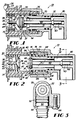
- Figs. 1-3 show a disconnect 10 according to the present invention for coupling to a bag valve 20 of a concentrate bag 24, such as for orange juice with pulp.
- Fig. 4 shows one general overall arrangement in which the disconnect 10 can be used including a postmix dispenser 12, a concentrate conduit 14, a pump 16, and a concentrate bag-in-box package 18.
- the package 18 includes a bag valve 20 connected to a bag spout 22, connected in turn to a collapsible bag 24 in a paperboard box 26.
- the box 26 need not be used; for example, the bag 24 can be placed in a refrigerator.
- Various concentrates can be used; the preferred one is orange juice with pulp.
- Figs. 1 and 2 show one embodiment of a disconnect 10 of the present invention connected to the bag valve 20. Before describing the disconnect 10 in detail, a brief description of the bag valve 20 will be set forth.
- the bag valve 20 can be snapped or screwed or otherwise connected to a bag spout 22 that includes a flange 23 heat sealed to a wall of the bag 24.
- the bag valve 20 includes a hollow, cylindrical body 30 having a juice concentrate passageway 40 therethrough, a movable sleeve 32, a spring 34, a poppet 36 connected to the body 30 in a fixed position therein, and a spider 38 with several spaced-apart arms 39 to support the poppet while allowing juice concentrate to flow through the passageway 40.
- the sleeve 32 includes a valve seat 42 for the poppet 36 and includes an annular end or edge 46 (to contact an annular end or edge 84 of a sleeve 70 of the disconnect, as will be described in detail below).
- the spider 38 can be formed integrally with the body 30 or it can be formed as a separate element that is then permanently attached to the body.
- the spider includes an axial opening 48 through which the anchor 44 on the end of the stem 49 of the poppet is pushed to lock the poppet to the spider 38 and thus to the body 30 of the bag valve in a fixed position.
- the bag valve 20 is opened and closed by movement of the sleeve 32 against the spring 34.
- the disconnect 10 includes a disconnect body 50 having a juice concentrate passageway 52 therethrough which is open to avoid having any areas or elements or features therein that could trap concentrate with pulp.
- the passageway 52 is preferably L-shaped, although other shapes can be used.
- a coupling nut 54 is rotatably connected to the outside surface of a proximal end 68 of the body 50 and includes internal screw threads 56 for connecting the disconnect 10 to the bag valve 20.
- the nut 54 is held to the body 50 by means of an annular wire 58 located in an annular groove on the outside surface of the body 50.
- the disconnect 10 also includes a poppet 60 fixedly connected to the body 50.
- the poppet 60 comprises a stem 62 and a head 64 having an O-ring 65 thereon.
- the stem 62 is fixed (by welding, for example) to a stem support 63 on the body 50 at the distal end 66 of the stem and extends concentrically through a portion of the passageway 52 and terminates at the head 64 at a location beyond the proximal end 68 of the body 50.
- a disconnect sleeve 70 is positioned inside the proximal end of the body 50 in sliding and sealing engagement with the inside surface of the body 50 and includes a passageway 71 therethrough and a poppet seat 72 on its proximal end in sealing engagement with O-ring 65 of the poppet head 64.
- the sleeve 70 has a spring retaining flange 74 on its external surface and a spring 76 is captured between the flange 74 and the proximal end 68 of the body 50 and is located around the outside surface of the sleeve 70, such that the sleeve 70 can be moved toward the body 50 and away from the poppet head 64 against the force of the spring 76 to open the passageway 52.
- the disconnect 10 is attached to the bag valve 20 as shown in Fig. 2 by screwing the nut 54 down onto the bag valve until it bottoms out on the bag valve in the position shown in Fig. 1 at which time the sleeve 70 has moved away from the poppet head 64 to provide an open passageway through the disconnect 10.
- the sleeve 32 in the bag valve 20 has moved away from the poppet 36 to also provide a passageway through the bag valve 20.
- the disconnect sleeve 70 includes an O-ring 80 in an O-ring groove 82 on its outer surface to provide a seal between the connector 10 and the bag valve 20.
- the connector 10 has an annular opening 86 between the sleeve 70 and the nut 54, into which bag valve body 30 fits when the two parts are coupled together.
- Fig. 3 shows a barbed fitting 90 having O-rings 92 attached to the disconnect by means of a retainer plate 94 and a bolt 96.
- the juice concentrate conduit 14 is pushed onto the barbed fitting.
- a barbed extension is made an integral part of the disconnect body to avoid the need for these separate elements.
- Fig. 5 shows a preferred embodiment of a disconnect 108 of the present invention which is identical to the embodiment shown in Figs. 1 and 2 with the exception that the stem 110 of the poppet valve 112 is fixed to a wall portion 116 of the disconnect body 114 without the need for the stem support 63.
- the wall portion 116 is thicker than in the embodiment of Figs. 1 and 2 so as to be able to support the poppet valve 112 without the need for any structure in the passageway 118.
- the passageway 118 can, if desired, smoothly curve through the body 114 so as to provide a substantially constant cross-sectional area along the entire length of the passageway to help avoid any areas where concentrate can be trapped.
Landscapes
- Engineering & Computer Science (AREA)
- General Engineering & Computer Science (AREA)
- Mechanical Engineering (AREA)
- Lift Valve (AREA)
- Containers And Packaging Bodies Having A Special Means To Remove Contents (AREA)
- Packages (AREA)
- Devices For Dispensing Beverages (AREA)
- Supplying Of Containers To The Packaging Station (AREA)
- Making Paper Articles (AREA)
- Joints That Cut Off Fluids, And Hose Joints (AREA)
- Closures For Containers (AREA)
- Taps Or Cocks (AREA)
Claims (6)
- Trennkupplung (10) für eine Saftkonzentratleitung, welche aufweist:(a) einen Trennkörper (50), welcher einen L-förmigen Saftkonzentratdurchgang (52) hat, welcher durch denselben geht;(b) eine Verbindungsmutter (54), welche drehbeweglich mit der äußeren Fläche eines proximalen Endes (68) des Körpers verbunden ist und Innengewindegänge (56) hat;(c) ein Tellerventil (60), welches mit dem Trennkörper in einer festen Position darin verbunden ist und einen Schaft (62) und einen Kopf (64) umfaßt, wobei der Schaft fest mit dem Körper verbunden ist und sich in den Durchgang erstreckt und am Kopf an einer Stelle außerhalb des proximalen Endes des Körpers endet, der Schaft parallel zum Durchgang (52) im proximalen Ende des Körpers ist, und wobei der Kopf an einem Ende des Schafts vorgesehen ist, und der Schaft mit dem Körper nur über das andere Ende (66) des Schafts verbunden ist, welcher sich bis zum Kontakt mit dem Körper erstreckt;(d) eine Trennhülse (70), welche gleitbeweglich im Inneren des Durchganges in dem Trennkörper in Dichtungseingriff mit einer Innenfläche des proximalen Endes des Körpers ist, wobei die Hülse folgendes hat:
(i) einen vollständig offenen Durchgang (71), welcher durch dieselbe geht und in kommunizierender Verbindung mit dem Körperdurchgang ist, (ii) einen Tellerventilsitz (72) am proximalen Ende in Dichtungseingriff mit dem Tellerventilkopf (64) und (iii) einen Federhalteflansch (74) auf ihrer äußeren Fläche;(e) eine Feder (76), welche auf der Außenseite der Trennhülse zwischen dem Flansch und dem proximalen Ende des Körpers derart angeordnet ist, daß die Hülse in Richtung auf den Körper zu und von dem Tellerventilkopf weg entgegen der Feder zum Öffnen des Durchgangs bewegt werden kann;(f) eine ringförmige O-Ringausnehmung (82) auf einer Außenseitenfläche der Trennhülse in der Nähe ihres proximalen Endes, und einen O-Ring (80) in der Ausnehmung, welcher der Innenseitenfläche zugewandt und durch die Verbindungsmutter geschützt ist; und(g) eine ringförmige Öffnung (86) zwischen der Außenseitenfläche der Trennhülse und der Innenseitenfläche der Mutter. - Trennkupplung nach Anspruch 1, bei der der Schaft (62) konzentrisch zu einem Schenkel des L-förmigen Durchgangs (52) ausgelegt ist, und direkt mit einem verdickten Wandabschnitt (116) des Trennkörpers verbunden ist, wobei der Wandabschnitt eine glatte, ununterbrochene Wandfläche des Durchgangs bildet, so daß die gesamte Stützkonstruktion für den Schaft außerhalb des Durchganges liegt.
- Trennkupplung nach Anspruch 2, bei der der L-förmige Durchgang (52) gleichmäßig gekrümmt zwischen den beiden Schenkeln verläuft.
- Trennkupplung nach einem der vorangehenden Ansprüche, bei der die Trennhülse (70) ein hohler Zylinder ist und bei der der Schaft (62) konzentrisch zu dem Trennhülsendurchgang (71) ist.
- Trennkupplung nach einem der vorangehenden Ansprüche in Kombination mit einem Beutelventil (20) für einen Saftkonzentratbeutel (24), wobei das Beutelventil einen zylindrischen, mit Außengewinde versehenen Körper (30) mit einem durch denselben gehenden Durchgang (40) hat, welcher derart ausgelegt ist, daß er in der ringförmigen Öffnung (86) aufgenommen und über eine Schraubverbindung mit der Mutter (54) verbunden ist.
- Kombination nach Anspruch 5, bei der das Beutelventil eine hohle, zylindrische, gleitbewegliche Hülse (32) im Inneren des Beutelventilkörpers umfaßt, die Beutelventilhülse einen Ventilsitz (42), ein Tellerventil (36), welches mit dem Beutelventilkörper in einer festen Position in demselben verbunden ist, und eine Feder (34) umfaßt, welche die Hülse in Sitzkontakt mit dem Tellerventil vorbelastet, die Hülse ein ringförmiges, proximales Ende (46) hat, welches den gleichen Durchmesser wie ein ringförmiges, proximales Ende (84) der Trennhülse (70) besitzt, so daß die Hülsenenden miteinander in Kontakt sind, wenn der Trennkupplungskörper zu Beginn mit dem Beutelventil verbunden ist, und daß dann, wenn die Trennkupplung auf das Beutelventil aufgeschraubt ist, bewirkt wird, daß beide Hülsen sich entgegen den Federn und von ihren zugeordneten Tellerventilen weg bewegen, um somit die Durchgänge zu öffnen.
Applications Claiming Priority (3)
| Application Number | Priority Date | Filing Date | Title |
|---|---|---|---|
| US285139 | 1988-12-16 | ||
| US07/285,139 US4890642A (en) | 1988-12-16 | 1988-12-16 | Disconnect for a bag valve |
| PCT/US1989/005698 WO1990007077A1 (en) | 1988-12-16 | 1989-12-14 | A disconnect for a bag valve |
Publications (2)
| Publication Number | Publication Date |
|---|---|
| EP0448643A1 EP0448643A1 (de) | 1991-10-02 |
| EP0448643B1 true EP0448643B1 (de) | 1994-07-27 |
Family
ID=23092905
Family Applications (1)
| Application Number | Title | Priority Date | Filing Date |
|---|---|---|---|
| EP90901416A Expired - Lifetime EP0448643B1 (de) | 1988-12-16 | 1989-12-14 | Entkupplungsvorrichtung für ein sackventil |
Country Status (11)
| Country | Link |
|---|---|
| US (1) | US4890642A (de) |
| EP (1) | EP0448643B1 (de) |
| JP (1) | JP2965690B2 (de) |
| AT (1) | ATE109262T1 (de) |
| AU (2) | AU629598B2 (de) |
| CA (1) | CA2005380C (de) |
| DE (1) | DE68917155T2 (de) |
| ES (1) | ES2057525T3 (de) |
| MY (1) | MY105150A (de) |
| PH (1) | PH26213A (de) |
| WO (1) | WO1990007077A1 (de) |
Families Citing this family (14)
| Publication number | Priority date | Publication date | Assignee | Title |
|---|---|---|---|---|
| FI92029C (fi) * | 1993-03-23 | 1994-09-26 | Cimcorp Oy | Liitäntälaite maalinsävytyskoneessa |
| US5325890A (en) * | 1993-07-15 | 1994-07-05 | Snap-Tite, Inc. | Sanitary coupling |
| DK0777604T3 (da) * | 1994-09-13 | 2003-10-06 | Ds Smith Uk Ltd | Ventilkonstruktion til væskebeholder, hvilken ventilkonstruktion er beregnet til tilslutningsledninger |
| US5983964A (en) * | 1995-12-05 | 1999-11-16 | Packaging Systems, L.L.C. | Method and apparatus for coupling with a spout |
| JP3869053B2 (ja) * | 1996-09-06 | 2007-01-17 | 日東工器株式会社 | 衛生用管継手 |
| US5823222A (en) * | 1996-10-31 | 1998-10-20 | Labatt Brewing Company Limited | Sanitary sampling device and method for using same |
| EP1305225A4 (de) * | 2000-06-21 | 2003-08-27 | Paul Francois Roos | Selbstschliessende kupplung |
| US6708741B1 (en) | 2000-08-24 | 2004-03-23 | Ocean Spray Cranberries, Inc. | Beverage dispenser |
| US8752734B2 (en) | 2009-02-11 | 2014-06-17 | Ds Smith Plastics Limited | Disposable assembly for a reusable urn or vessel |
| US10160583B2 (en) | 2015-05-27 | 2018-12-25 | Ds Smith Plastics Limited | Co-injection molded dispensing components |
| US10112820B1 (en) | 2016-01-19 | 2018-10-30 | Dss Rapak, Inc. | Beverage dispensing system with disposable liner and faucet |
| KR102083574B1 (ko) * | 2017-11-24 | 2020-03-02 | 임근만 | 음료분배장치 |
| US12000514B2 (en) * | 2021-06-28 | 2024-06-04 | Microsoft Technology Licensing, Llc | Systems and methods for a floating quick disconnect in liquid cooling |
| TWI854628B (zh) * | 2023-05-03 | 2024-09-01 | 吳樹木 | 氣嘴接頭 |
Family Cites Families (11)
| Publication number | Priority date | Publication date | Assignee | Title |
|---|---|---|---|---|
| GB857583A (en) * | 1956-03-12 | 1961-01-04 | Bo Nilsson Hoffstrom | Improvements in or relating to plug-and-socket couplings, for example for fluid lines |
| US3117592A (en) * | 1957-07-31 | 1964-01-14 | Aeroquip Corp | Self-sealing coupling |
| US2962303A (en) * | 1957-12-06 | 1960-11-29 | Titeflex Inc | Disconnect couplings |
| FR2216219B1 (de) * | 1973-02-02 | 1977-09-02 | Zenith Aviat | |
| US4137930A (en) * | 1977-01-26 | 1979-02-06 | Scholle Corporation | Single operation normally closed coupling valve |
| NL7900763A (nl) * | 1979-01-31 | 1980-08-04 | Vsh Fabrieken Nv | Snelkoppeling, in het bijzonder voor gassen onder hoge druk. |
| US4286636A (en) * | 1979-07-19 | 1981-09-01 | The Coca-Cola Company | Dip tube and valve with quick-disconnect coupling for a collapsible container |
| US4287914A (en) | 1980-01-16 | 1981-09-08 | Aeroquip Corporation | Self sealing coupling with full flow relief valve |
| US4757919A (en) * | 1986-09-23 | 1988-07-19 | The Coca-Cola Company | Shut-off valve for juice dispensing system |
| GB8628442D0 (en) * | 1986-11-27 | 1986-12-31 | Unilever Plc | Coupling |
| JP5898552B2 (ja) | 2012-03-30 | 2016-04-06 | 積水化成品工業株式会社 | ポリスチレン系樹脂発泡シート及びポリスチレン系樹脂製の成形容器 |
-
1988
- 1988-12-16 US US07/285,139 patent/US4890642A/en not_active Expired - Fee Related
-
1989
- 1989-12-13 CA CA002005380A patent/CA2005380C/en not_active Expired - Lifetime
- 1989-12-14 AT AT90901416T patent/ATE109262T1/de not_active IP Right Cessation
- 1989-12-14 AU AU48273/90A patent/AU629598B2/en not_active Expired
- 1989-12-14 ES ES90901416T patent/ES2057525T3/es not_active Expired - Lifetime
- 1989-12-14 JP JP2501890A patent/JP2965690B2/ja not_active Expired - Fee Related
- 1989-12-14 EP EP90901416A patent/EP0448643B1/de not_active Expired - Lifetime
- 1989-12-14 WO PCT/US1989/005698 patent/WO1990007077A1/en not_active Ceased
- 1989-12-14 MY MYPI89001752A patent/MY105150A/en unknown
- 1989-12-14 DE DE68917155T patent/DE68917155T2/de not_active Expired - Lifetime
- 1989-12-15 PH PH39716A patent/PH26213A/en unknown
-
1992
- 1992-08-21 AU AU21196/92A patent/AU643153B2/en not_active Expired
Also Published As
| Publication number | Publication date |
|---|---|
| US4890642A (en) | 1990-01-02 |
| CA2005380C (en) | 1997-12-02 |
| AU643153B2 (en) | 1993-11-04 |
| AU2119692A (en) | 1992-11-12 |
| ES2057525T3 (es) | 1994-10-16 |
| AU4827390A (en) | 1990-07-10 |
| DE68917155T2 (de) | 1995-03-02 |
| ATE109262T1 (de) | 1994-08-15 |
| MY105150A (en) | 1994-08-30 |
| AU629598B2 (en) | 1992-10-08 |
| WO1990007077A1 (en) | 1990-06-28 |
| CA2005380A1 (en) | 1990-06-16 |
| PH26213A (en) | 1992-03-18 |
| JP2965690B2 (ja) | 1999-10-18 |
| JPH04502444A (ja) | 1992-05-07 |
| DE68917155D1 (de) | 1994-09-01 |
| EP0448643A1 (de) | 1991-10-02 |
Similar Documents
| Publication | Publication Date | Title |
|---|---|---|
| AU629598B2 (en) | A disconnect for a bag valve | |
| US8479785B2 (en) | Slider valve fitment and collar | |
| US5477883A (en) | Self-sealing bag valve | |
| US6892760B2 (en) | Self closing coupling | |
| US7487951B2 (en) | Double slider valve fitment | |
| US3868049A (en) | Keg tapping device | |
| US4510969A (en) | Connector for pressurized source of beverage concentrate | |
| WO1995021101B1 (en) | Back-flow preventing bag valve for bag-in-box container | |
| US4757919A (en) | Shut-off valve for juice dispensing system | |
| EP0084699A1 (de) | Ausschankanlage | |
| CA2648550C (en) | No-drip check valves | |
| US3822716A (en) | Beverage tapping device | |
| US3632023A (en) | Tapping device for beer kegs and the like | |
| GB2383996A (en) | A container comprising a valve and a deflector plate |
Legal Events
| Date | Code | Title | Description |
|---|---|---|---|
| PUAI | Public reference made under article 153(3) epc to a published international application that has entered the european phase |
Free format text: ORIGINAL CODE: 0009012 |
|
| 17P | Request for examination filed |
Effective date: 19910709 |
|
| AK | Designated contracting states |
Kind code of ref document: A1 Designated state(s): AT BE CH DE ES FR GB IT LI LU NL SE |
|
| 17Q | First examination report despatched |
Effective date: 19920204 |
|
| GRAA | (expected) grant |
Free format text: ORIGINAL CODE: 0009210 |
|
| AK | Designated contracting states |
Kind code of ref document: B1 Designated state(s): AT BE CH DE ES FR GB IT LI LU NL SE |
|
| PG25 | Lapsed in a contracting state [announced via postgrant information from national office to epo] |
Ref country code: NL Effective date: 19940727 Ref country code: LI Effective date: 19940727 Ref country code: CH Effective date: 19940727 Ref country code: AT Effective date: 19940727 |
|
| REF | Corresponds to: |
Ref document number: 109262 Country of ref document: AT Date of ref document: 19940815 Kind code of ref document: T |
|
| REF | Corresponds to: |
Ref document number: 68917155 Country of ref document: DE Date of ref document: 19940901 |
|
| ITF | It: translation for a ep patent filed | ||
| REG | Reference to a national code |
Ref country code: ES Ref legal event code: FG2A Ref document number: 2057525 Country of ref document: ES Kind code of ref document: T3 |
|
| REG | Reference to a national code |
Ref country code: CH Ref legal event code: PL |
|
| ET | Fr: translation filed | ||
| PG25 | Lapsed in a contracting state [announced via postgrant information from national office to epo] |
Ref country code: LU Free format text: LAPSE BECAUSE OF NON-PAYMENT OF DUE FEES Effective date: 19941231 |
|
| NLV1 | Nl: lapsed or annulled due to failure to fulfill the requirements of art. 29p and 29m of the patents act | ||
| EAL | Se: european patent in force in sweden |
Ref document number: 90901416.9 |
|
| PLBE | No opposition filed within time limit |
Free format text: ORIGINAL CODE: 0009261 |
|
| STAA | Information on the status of an ep patent application or granted ep patent |
Free format text: STATUS: NO OPPOSITION FILED WITHIN TIME LIMIT |
|
| 26N | No opposition filed | ||
| PGFP | Annual fee paid to national office [announced via postgrant information from national office to epo] |
Ref country code: SE Payment date: 19991125 Year of fee payment: 11 |
|
| PG25 | Lapsed in a contracting state [announced via postgrant information from national office to epo] |
Ref country code: SE Free format text: LAPSE BECAUSE OF NON-PAYMENT OF DUE FEES Effective date: 20001215 |
|
| EUG | Se: european patent has lapsed |
Ref document number: 90901416.9 |
|
| PGFP | Annual fee paid to national office [announced via postgrant information from national office to epo] |
Ref country code: FR Payment date: 20011211 Year of fee payment: 13 |
|
| PGFP | Annual fee paid to national office [announced via postgrant information from national office to epo] |
Ref country code: ES Payment date: 20011212 Year of fee payment: 13 |
|
| PGFP | Annual fee paid to national office [announced via postgrant information from national office to epo] |
Ref country code: BE Payment date: 20011220 Year of fee payment: 13 |
|
| REG | Reference to a national code |
Ref country code: GB Ref legal event code: IF02 |
|
| PG25 | Lapsed in a contracting state [announced via postgrant information from national office to epo] |
Ref country code: ES Free format text: LAPSE BECAUSE OF NON-PAYMENT OF DUE FEES Effective date: 20021216 |
|
| PG25 | Lapsed in a contracting state [announced via postgrant information from national office to epo] |
Ref country code: BE Free format text: LAPSE BECAUSE OF NON-PAYMENT OF DUE FEES Effective date: 20021231 |
|
| BERE | Be: lapsed |
Owner name: THE *COCA-COLA CY Effective date: 20021231 |
|
| PG25 | Lapsed in a contracting state [announced via postgrant information from national office to epo] |
Ref country code: FR Free format text: LAPSE BECAUSE OF NON-PAYMENT OF DUE FEES Effective date: 20030901 |
|
| REG | Reference to a national code |
Ref country code: FR Ref legal event code: ST |
|
| REG | Reference to a national code |
Ref country code: ES Ref legal event code: FD2A Effective date: 20021216 |
|
| PG25 | Lapsed in a contracting state [announced via postgrant information from national office to epo] |
Ref country code: IT Free format text: LAPSE BECAUSE OF NON-PAYMENT OF DUE FEES;WARNING: LAPSES OF ITALIAN PATENTS WITH EFFECTIVE DATE BEFORE 2007 MAY HAVE OCCURRED AT ANY TIME BEFORE 2007. THE CORRECT EFFECTIVE DATE MAY BE DIFFERENT FROM THE ONE RECORDED. Effective date: 20051214 |
|
| PGFP | Annual fee paid to national office [announced via postgrant information from national office to epo] |
Ref country code: DE Payment date: 20081219 Year of fee payment: 20 |
|
| PGFP | Annual fee paid to national office [announced via postgrant information from national office to epo] |
Ref country code: GB Payment date: 20081216 Year of fee payment: 20 |
|
| REG | Reference to a national code |
Ref country code: GB Ref legal event code: PE20 Expiry date: 20091213 |
|
| PG25 | Lapsed in a contracting state [announced via postgrant information from national office to epo] |
Ref country code: GB Free format text: LAPSE BECAUSE OF EXPIRATION OF PROTECTION Effective date: 20091213 |