EP0447935B1 - Circuit arrangement for sending and receiving tone frequency signals on telephone lines - Google Patents
Circuit arrangement for sending and receiving tone frequency signals on telephone lines Download PDFInfo
- Publication number
- EP0447935B1 EP0447935B1 EP91103815A EP91103815A EP0447935B1 EP 0447935 B1 EP0447935 B1 EP 0447935B1 EP 91103815 A EP91103815 A EP 91103815A EP 91103815 A EP91103815 A EP 91103815A EP 0447935 B1 EP0447935 B1 EP 0447935B1
- Authority
- EP
- European Patent Office
- Prior art keywords
- signal processor
- digital signal
- dsp
- digital
- circuit arrangement
- Prior art date
- Legal status (The legal status is an assumption and is not a legal conclusion. Google has not performed a legal analysis and makes no representation as to the accuracy of the status listed.)
- Expired - Lifetime
Links
Images
Classifications
-
- H—ELECTRICITY
- H04—ELECTRIC COMMUNICATION TECHNIQUE
- H04Q—SELECTING
- H04Q3/00—Selecting arrangements
- H04Q3/42—Circuit arrangements for indirect selecting controlled by common circuits, e.g. register controller, marker
Abstract
Description
Die Erfindung betrifft eine Schaltungsanordnung zum
Senden und Empfangen von Tonfrequenzsignalen an Verbindungsleitungen
von Kommunikations-Vermittlungsanlagen
nach dem Oberbegriff des Patentanspruchs 1. The invention relates to a circuit arrangement for
Sending and receiving audio frequency signals on connecting lines
of communication switching systems
according to the preamble of
Aus der GB 2 200 816 A ist ein digitales Signalverarbeitungssystem bekannt, das mehrere digitale Signalprozessoren aufweist. Diese können mit Anwendungsprogrammen aus einer Zentraleinheit geladen werden. Dies erlaubt die Durchführung verschiedener Dienstmerkmale wie Tongenerierung und -detektion. GB 2 200 816 A is a digital signal processing system known that has multiple digital signal processors. This can be loaded with application programs from a central unit will. This allows various service features to be carried out such as tone generation and detection.
Eine Schaltungsanordnung zum Durchschalten von Tonund Niederfrequenzsignalen im Sprechweg von Verbindungsleitungsübertragungen in Fernsprechvermittlungsanlagen ist aus der DE-PS 30 17 740 bekannt. Dort wird ein matrixförmig aufgebauter Koppelbaustein benutzt, um je nach Verbindungszustand Tongeneratoren oder Mehrfrequenz-Wahl-Sender an den Sprechweg der Verbindungsleitungs-Übertragung anzuschalten. Es ist außerdem vorgesehen, Tonfrequenzempfänger an den Sprechweg anzuschalten. Dies geschieht durch eine in der Verbindungsleitungs-Übertragung befindliche Steuereinrichtung, welche die Befehle an den Koppelbaustein gibt, damit dort die betreffenden Koppelpunkte so lange durchgeschaltet werden, wie dies für die jeweilige Funktion erforderlich ist. Hierbei wird jedoch für jede einzelne Verbindungsleitungs-Übertragung eine eigene Steuereinrichtung benötigt. Die zu sendenden Tonfrequenzen für Töne oder für Wahlinformation werden zentral erzeugt, so daß es nicht möglich ist, individuelle Anpassungen pro Verbindungsleitung vorzunehmen. Wenn dies verlangt wird, so müßten auch die Tongeneratoren und die Mehrfrequenz-Wahl-Sender pro Verbindungsleitungs-Übertragung vorgesehen werden. Das gleiche trifft zu für einen oder mehrere TonfrequenzEmpfänger.A circuit arrangement for switching sound and Low frequency signals in the speech path of trunk line transmissions in telephone exchanges is known from DE-PS 30 17 740. There if a matrix module is used, to tone generators depending on the connection status or multi-frequency voting transmitter to the speech path of the Switch on connecting line transmission. It is also provided audio frequency receiver to the Turn on speech path. This happens through a in the trunk transmission Control device which sends the commands to the coupling module there so that the relevant crosspoints be switched through as long as this is required for the respective function. Here however, for each individual trunk transmission needs its own control device. The tone frequencies to be sent for tones or for dialing information are generated centrally so it doesn't it is possible to make individual adjustments per connecting line to make. If this is required, it should also the tone generators and the multi-frequency transmitters can be provided per connection line transmission. The same applies to one or more audio frequency receivers.
Die Aufgabe der Erfindung besteht darin, eine Schaltungsanordnung anzugeben, womit es möglich ist, mit einer Steuereinrichtung mehrere Verbindungsleitungen zu bedienen, wobei individuell pro Verbindungsleitung verschiedenartige Tonfrequenzen gesendet und empfangen werden können. Außerdem sollen die Voraussetzungen geschaffen werden, daß eine individuelle Anpassung der Sende- und Empfangspegel ohne Änderung der Hardwaremöglich ist.The object of the invention is a circuit arrangement indicate what is possible with a Control device to operate several connecting lines, different for each connecting line Tone frequencies sent and received can be. In addition, the conditions should be created be that an individual adjustment of the Sending and receiving level is possible without changing the hardware.
Zur Lösung dieser Aufgabe ist eine Merkmalskombination
vorgesehen, wie sie im Patentanspruch 1 angegeben ist.A combination of features is used to solve this task
provided as specified in
Damit wird in vorteilhafter Weise erreicht, daß durch individuelle Programmierung festgelegt werden kann, welche Tonfrequenzen auf der jeweils ausgewählten Verbindungsleitung gesendet werden und welche Tonfrequenzen dort empfangen werden. Durch den Einsatz eines digitalen Signalprozessors ist es möglich, eine große Variationsbreite von verschiedenen Tonfrequenzen und Kombinationen zu erreichen, ohne daß die Kosten wesentlich steigen. Mit einer peripheren Steuereinrichtung können mehrere Verbindungsleitungen bedient werden. This is advantageously achieved by individual programming can be set, what sound frequencies on the selected connection line are sent and what sound frequencies be received there. By using a digital signal processor it is possible to get a large one Variation range of different sound frequencies and To achieve combinations without making the cost essential climb. With a peripheral control device several connection lines can be operated.
In den Unteransprüchen sind vorteilhafte Weiterbildungen der Erfindung angegeben.Advantageous further developments are in the subclaims specified the invention.
Ein Ausführungsbeispiel der Erfindung wird nachfolgend anhand von Zeichnungen näher erläutert.An embodiment of the invention is as follows explained in more detail with reference to drawings.
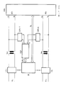
In der Zeichnung ist dargestellt, wie jede einzelne Verbindungsleitung VL1 - VLn durch eine Leitungsschnittstelle LS1 - LSn abgeschlossen ist. Über diese Leitungsschnittstellen LS1 - LSn werden alle vermittlungstechnischen Kennzeichen über die Verbindungsleitungen VL1 - VLn gesendet und empfangen, welche nicht innerhalb des Sprachfrequenzbandes liegen. Wenn derartige vermittlungstechnische Kennzeichen gesendet werden sollen, so gibt die analoge Vermittlungsanlage AVA über ein Steuerleitungsbündel SL entsprechende Befehle an die dezentrale Steuereinrichtung SE. Dort werden diese Befehle logisch verarbeitet und als Steuerkriterien zu den betreffenden Leitungsschnittstellen LS1 - LSn geleitet, wo die entsprechenden Schaltaufträge ausgeführt werden. Solche Schaltaufträge können beispielsweise darin bestehen, daß Gleichstromschleifen geschlossen oder geöffnet werden, daß Gleichspannungen angeschaltet oder abgeschaltet werden, oder daß niederfrequente Wechselströme ausgesendet werden.The drawing shows how each individual connecting line VL1 - VLn through a line interface LS1 - LSn is complete. Via these line interfaces LS1 - LSn are all switching-related Identification via the connecting lines VL1 - VLn sent and received, which are not within the Voice frequency band are. If such mediation License plates should be sent, see above gives the analog switching system AVA over a control line bundle SL appropriate commands to the decentralized Control device SE. There are these commands processed logically and as tax criteria for the relevant Line interfaces LS1 - LSn routed, where the corresponding switching orders are carried out. Such switching orders can consist, for example, of that DC loops closed or opened that DC voltages are switched on or be switched off, or that low-frequency alternating currents be sent out.
Beim Empfangen von über die Verbindungsleitung VL1 - VLn eintreffenden Schaltkennzeichen werden diese von den Leitungsschnittstellen LS1 - LSn erkannt und an die dezentrale Steuereinrichtung SE weitergegeben. Von dort aus gelangen sie zusammen mit einer entsprechenden Leitungsadresse über das Steuerleitungsbündel SL zur zentralen Steuerung der analogen Vermittlungsanlage AVA. When receiving via the connecting line VL1 - VLn Incoming switching indicators are used by the Line interfaces LS1 - LSn recognized and sent to the decentralized Control device SE passed on. From there they arrive together with a corresponding one Line address via the control line bundle SL to central control of the analog switching system AVA.
Die dezentrale Steuereinrichtung SE erkennt anhand der von den Leitungsschnittstellen LS1 - LSn empfangenen Kriterien und anhand der von der analogen Vermittlungsanlage AVA abgegebenen Befehle jederzeit, welcher Verbindungszustand auf den einzelnen Verbindungsleitungen VL1 - VLn herrscht. Daraufhin werden über Steuerbefehlsleitungen SBL Befehle an den digitalen Signalprozessor DSP gegeben, womit dieser veranlaßt wird, sich auf Senden oder Empfangen für die betreffende Verbindungsleitung VL1 - VLn einzustellen. Für jede Verbindungsleitung VL1 - VLn ist je ein Eingang E1 - En und ein Ausgang A1 - An des digitalen Signalprozessors DSP zuständig. Daran ist je eine Wandlerschaltung COFI1 - COFIn angeschlossen. Der Analogteil dieser Wandlerschaltungen COFI1 - COFIn ist mit den Sprechadern verbunden. Die Sprechadern sind jeweils mit Übertragern UE1 - UEn an die Verbindungsleitungen VL1 - VLn angekoppelt. Die andere Seite der Sprechadern al/bl - an/bn sind zur analogen Vermittlungsanlage AVA geführt, wo sie über Anschlußorgane AO1 - AOn zu den entsprechenden Koppelpunkten gelangen.The decentralized control device SE recognizes on the basis of the received by the line interfaces LS1 - LSn Criteria and based on that of the analog switching system AVA issued commands at any time, what connection status on the individual connecting lines VL1 - VLn prevails. Thereupon, via control command lines SBL commands to the digital signal processor DSP given, causing it to send or receive for the relevant connection line VL1 - VLn to set. For every connecting line VL1 - VLn is an input E1 - En and an output A1 - Responsible for the digital signal processor DSP. There is a converter circuit COFI1 - COFIn on each connected. The analog part of these converter circuits COFI1 - COFIn is connected to the speaking wires. The Speech cores are each with transmitters UE1 - UEn the connecting lines VL1 - VLn coupled. The other side of the speaking wires al / bl - an / bn are for analog switching system AVA led, where it over Connection elements AO1 - AOn to the corresponding coupling points reach.
Wenn auf einer der Verbindungsleitungen, z. B. VL 1 ein
Verbindungszustand herrscht, bei dem über die Verbindungsleitung
VL1 einlaufende Tonfrequenzen zu empfangen
sind, so ist von der Steuereinrichtung SE über die
Steuerbefehlsleitung SBL ein entsprechender Befehl an
den digitalen Signalprozessor DSP gegeben worden. Die
Tonfrequenzen, welche auf der Verbindungsleitung VL1
empfangen werden, werden in der Wandlerschaltung COFI1
digitalisiert und gelangen an den zugehörigen Eingang El
des digitalen Signalprozessors DSP. Durch den von der
Steuereinrichtung SE an den digitalen Signalprozessor
DSP abgegebenen Befehl wird dieser nicht nur auf Empfang
eingestellt für die betreffende Verbindungsleitung
VL1, sondern es werden auch digitale Filter innerhalb
des digitalen Signalprozessors DSP gebildet, womit
die Frequenz des zu empfangenden Tonfrequenzsignals festgelegt
ist. Wenn ein Tonfrequenzsignal mit erwarteter
Frequenz und Pegel empfangen wird, so meldet sich der digitale Signalprozessor
DSP über die Steuerbefehlsleitungen SBL
dies an die periphere Steuereinrichtung SE. Von dort
aus gelangt dann dieses Kriterium über die Steuerleitungen
SL zur analogen Vermittlungsanlage AVA, wobei
dieser Meldung die Adresse der betreffenden Verbindungsleitung
VL 1 beigegeben ist.If on one of the connecting lines, e.g. B. VL 1 a
Connection status prevails in which over the connecting line
VL1 to receive incoming sound frequencies
are from the control device SE via the
Control command line SBL a corresponding command
given the digital signal processor DSP. The
Sound frequencies, which on the connecting line VL1
are received in the converter circuit COFI1
digitized and arrive at the associated entrance El
of the digital signal processor DSP. By the of the
Control device SE to the digital signal processor
The command given to DSP is not only received
set for the relevant connection line
VL1, but there are also digital filters inside
of the digital signal processor DSP, which
set the frequency of the audio frequency signal to be received
is. If an audio frequency signal with expected
Frequency and level is received, the digital signal processor reports
DSP over the control command lines SBL
this to the peripheral control device SE. From there
This criterion then comes from the control lines
SL to the analog switching system AVA, whereby
this message the address of the connection line concerned
Wenn aufgrund des Verbindungszustandes einer Verbindungsleitung, z. B. VLn, wobei auch die Verkehrsrichtung beachtet wird, festgestellt wird, daß Tonfrequenzsignale zu senden sind, so geschieht dies ebenfalls dadurch, daß die Steuereinrichtung SE entsprechende Befehle an den digitalen Signalprozessor DSP abgibt. Der zu sendenden Frequenz entsprechend werden innerhalb des digitalen Signalprozessors DSP aufgrund der anliegenden Befehlsstruktur digitale Generatoren gebildet, wodurch das digitalisierte Tonfrequenzsignal am zugehörigen Ausgang An abgegeben wird. Von dort gelangt es zu der zugeordneten Wandlerschaltung COFIn, wo es in eine analoge Form umgewandelt wird und auf den Sprechweg gelangt. Auf diese Weise können den Eigenschaften der jeweiligen Verbindungsleitung VLn entsprechend sowohl einfache Tonfrequenzsignale in verschiedenen Rhythmen als auch Wahl information nach dem Mehrfrequenzverfahren ausgesendet werden.If due to the connection status of a connecting line, e.g. B. VLn, taking into account the direction of traffic , it is found that audio frequency signals are to be sent, this also happens by that the control device SE corresponding commands outputs the digital signal processor DSP. The one to send Frequency will be corresponding within the digital Signal processor DSP due to the existing command structure digital generators formed, whereby the digitized audio frequency signal at the associated output Is delivered to. From there it gets to the assigned one Converter circuit COFIn, where there is an analog Form is converted and gets on the speech path. In this way, the properties of each Connection line VLn accordingly both simple tone frequency signals in different rhythms as well as election information using the multi-frequency method be sent out.
Innerhalb des digitalen Signalprozessors DSP ist für jede Verbindungsleitung VL1 - VLn im einzelnen festgelegt, welche Frequenzen und welche Schaltzeiten für die einzelnen Töne erforderlich sind. Dies gilt sowohl für das Senden als auch für das Empfangen der auf dem Sprechweg auszutauschenden Tonfrequenzsignale. Die dazu notwendigen Steuerkriterein werden zunächst zwischen der analogen Vermittlungsanlage AVA und der dezentralen Steuereinrichtung SE ausgetauscht, und von dort in entsprechend umgesetzter Form als Steuerbefehle über die Steuerbefehlsleitung SBL zwischen dem digitalen Signalprozessor und der dezentralen Steuereinrichtung SE ausgetauscht.Within the digital signal processor DSP is for each connecting line VL1 - VLn specified in detail, what frequencies and what switching times for the individual tones are required. This applies to both for sending as well as receiving the on the Audio frequency signals to be exchanged. The one necessary tax criteria are first between the analog switching system AVA and the decentralized Control device SE exchanged, and from there in accordingly implemented form as control commands via the Control command line SBL between the digital signal processor and the decentralized control device SE exchanged.
Mit dem digitalen Signalprozessor DSP ist es außerdem möglich, während einer Gesprächsverbindung, die sich im Haltezustand befindet, besondere Informationen auszusenden. Dabei kann es sich um ausgewählte Musikstücke handeln, die einen wartenden Teilnehmer veranlassen, die Verbindung aufrechtzuerhalten. Dieses unter dem Begriff Music on Hold international bekannte Merkmal ist innerhalb des digitalen Signalprozessors DSP für jede einzelne Verbindungsleitung VL1 - VLn individuell einrichtbar. Es kann also ein begrenzter Vorrat von Melodien bereitgehalten werden, welche wahlweise den jeweiligen Verbindungsleitungen VL1 - VLn zugeordnet werden können. Es kann also für dieses Merkmal bestimmt werden, welche Melodie oder auch Ansage auf einer Verbindungsleitung VL1 - VLn gesendet werden soll.With the digital signal processor DSP it is also possible during a call that is is on hold to send out special information. It can be selected pieces of music act which cause a waiting participant to act Maintain connection. This under the term Music on Hold internationally known feature is within of the digital signal processor DSP for each one Connection line VL1 - VLn individually adjustable. So there can be a limited supply of melodies are kept ready, which either the respective Connection lines VL1 - VLn can be assigned. So it can be determined for this characteristic which Melody or announcement on a connecting line VL1 - VLn should be sent.
Claims (5)
- Circuit arrangement for sending and receiving voice-frequency signals on analogue-operated trunks of communications exchanges, the tone generators and tone receivers being switched on by a decentralized control device (SE), and there being connected to it a digital signal processor (DSP) which has a plurality of digital inputs (E1 to En) and at least one digital output (A1 to An), and the digital signal processor (DSP) receiving from the control device (SE) setting instructions in which parameters are contained which characterize the signals or signal sequences respectively to be sent or to be received, and the determination of the signals or signal sequences to be sent or to be received is performed in each case as a function of the connection status of the relevant trunk (VL) established by the control device, for the purpose of selecting which trunk the digital signal processor (DSP) also receives appropriate information with the setting instructions, with the result that a specific trunk (VL) can be selected using the setting instructions if the control device (SE) and the digital signal processor (DSP) are responsible for a plurality of trunks, characterized in that in each case a digital input (for example En) of the digital signal processor (DSP) is connected to a digital output of a converter circuit (COFI/n), in that the associated digital output (An) of the signal processor (DSP) is connected to the digital input of the same converter circuit (COFI/n), and in that digital generators for sending and digital filters for receiving are formed inside the digital signal processor (DSP) on the basis of the setting instructions.
- Circuit arrangement according to Claim 1, characterized in that when sending voice-frequency signals both simple audible tones or audible tone sequences and pieces of music and/or announcements are possible, the structures of which are stored parametrically inside the digital signal processor (DSP).
- Circuit arrangement according to Claim 1, characterized in that voice-frequency signals to be sent can be selected specifically as a function of the trunk (VL) respectively to be operated, with the aid of the setting instructions for the digital signal processor (DSP).
- Circuit arrangement according to Claim 1, characterized in that voice-frequency selection information is sent and received by means of the digital signal processor (DSP).
- Circuit arrangement according to Claim 1, characterized in that the send and receive levels of the voice-frequency signals are prescribed by means of the setting instructions for the digital signal processor (DSP).
Applications Claiming Priority (2)
| Application Number | Priority Date | Filing Date | Title |
|---|---|---|---|
| DE4008449 | 1990-03-16 | ||
| DE4008449A DE4008449C2 (en) | 1990-03-16 | 1990-03-16 | Circuit arrangement for sending and receiving audio frequency signals on connecting lines of communication switching systems |
Publications (3)
| Publication Number | Publication Date |
|---|---|
| EP0447935A2 EP0447935A2 (en) | 1991-09-25 |
| EP0447935A3 EP0447935A3 (en) | 1994-03-23 |
| EP0447935B1 true EP0447935B1 (en) | 1998-08-19 |
Family
ID=6402366
Family Applications (1)
| Application Number | Title | Priority Date | Filing Date |
|---|---|---|---|
| EP91103815A Expired - Lifetime EP0447935B1 (en) | 1990-03-16 | 1991-03-13 | Circuit arrangement for sending and receiving tone frequency signals on telephone lines |
Country Status (4)
| Country | Link |
|---|---|
| EP (1) | EP0447935B1 (en) |
| AT (1) | ATE170032T1 (en) |
| DE (1) | DE4008449C2 (en) |
| ES (1) | ES2118724T3 (en) |
Families Citing this family (1)
| Publication number | Priority date | Publication date | Assignee | Title |
|---|---|---|---|---|
| DE4141493C1 (en) * | 1991-12-16 | 1993-08-12 | Siemens Ag, 8000 Muenchen, De |
Family Cites Families (6)
| Publication number | Priority date | Publication date | Assignee | Title |
|---|---|---|---|---|
| DE3220511C3 (en) * | 1982-06-01 | 1987-03-26 | Telefonbau & Normalzeit Gmbh | CIRCUIT ARRANGEMENT FOR A TELECOMMUNICATION SYSTEM WITH CONNECTION-INDIVIDUAL CABLE TRANSMISSIONS. |
| US4623760A (en) * | 1983-10-28 | 1986-11-18 | At&T Bell Laboratories | Signaling protocol interface channel unit |
| DE3343646A1 (en) * | 1983-12-02 | 1985-06-13 | Standard Elektrik Lorenz Ag, 7000 Stuttgart | CIRCUIT ARRANGEMENT FOR DETECTING AND EVALUATING AC VOLTAGE SIGNALS ON OFF-LINE Veins |
| DE3411205C2 (en) * | 1984-03-27 | 1986-12-11 | Telefonbau Und Normalzeit Gmbh, 6000 Frankfurt | Procedure for exchanging license plates between telephone exchanges connected as main and sub-systems |
| JPS6338388A (en) * | 1986-08-01 | 1988-02-18 | Nec Corp | Supervising circuit for line signal of telephone exchange |
| CA1279393C (en) * | 1987-01-23 | 1991-01-22 | A. David Milton | Digital signal processing system |
-
1990
- 1990-03-16 DE DE4008449A patent/DE4008449C2/en not_active Expired - Fee Related
-
1991
- 1991-03-13 EP EP91103815A patent/EP0447935B1/en not_active Expired - Lifetime
- 1991-03-13 ES ES91103815T patent/ES2118724T3/en not_active Expired - Lifetime
- 1991-03-13 AT AT91103815T patent/ATE170032T1/en not_active IP Right Cessation
Also Published As
| Publication number | Publication date |
|---|---|
| ES2118724T3 (en) | 1998-10-01 |
| EP0447935A2 (en) | 1991-09-25 |
| DE4008449C2 (en) | 1994-10-20 |
| DE4008449A1 (en) | 1991-09-19 |
| ATE170032T1 (en) | 1998-09-15 |
| EP0447935A3 (en) | 1994-03-23 |
Similar Documents
| Publication | Publication Date | Title |
|---|---|---|
| DE1441120A1 (en) | Multi-channel radio telephone network | |
| EP0929200A2 (en) | Method and device for providing direct inward dialling function in telecommunication exchanges | |
| EP0005220A2 (en) | Circuitry for time division multiplex digital switching telecommunication exchanges, in particular telephone exchanges | |
| EP0446884A2 (en) | Circuit arrangement for conversion of signalling and information between analog trunks and digital line circuits in a communications switch exchange | |
| EP0447935B1 (en) | Circuit arrangement for sending and receiving tone frequency signals on telephone lines | |
| DE4236565C2 (en) | Door intercom | |
| EP0095675B1 (en) | Circuit for a telephone exchange with line junctors which are individually allocated to connections | |
| EP0460404B1 (en) | Method for data transmission in communication exchanges | |
| EP0037540B1 (en) | Method and circuit for feeding call signals to telecommunication lines, especially in telephone exchanges | |
| DE3920721A1 (en) | Telephone terminal operation with data indication - involves initialising by transmission of specific dial signal to exchange | |
| DE2723666C3 (en) | Method for processing waiting function sequences in a centrally controlled switching system, in particular in a centrally controlled telephone exchange | |
| DE3014420C2 (en) | Circuit arrangement for generating an acoustic signal at subscriber stations in telephone systems, in particular telephone branch exchange systems | |
| EP0901268A2 (en) | Apparatus with a door station and a plurality of dwelling stations interconnected by a two wire bus | |
| DE3926149C2 (en) | Circuit board for an attendant | |
| DE4006048C2 (en) | ||
| DE3102691C2 (en) | Circuit arrangement for the remote-controlled switching of a special service subscriber circuit in telephone systems | |
| DE4016629C2 (en) | Service telephone unit | |
| DE3531147C2 (en) | ||
| DE3910533C1 (en) | ||
| DE2559064B2 (en) | Matching transmission circuit | |
| DE2831060C2 (en) | Audio signal switch-on device | |
| DE19704026B4 (en) | door hands-free | |
| DE4236046C1 (en) | Intercom system with centralised control - uses duplex amplifiers in connection path between calling and called speech stations with respective amplifier paths for each direction | |
| DE973727C (en) | Circuit arrangement for telephone systems with dialer operation, which allow the mutual switching of two-wire and four-wire operated stations within one and the same local network | |
| DE3730232C1 (en) | Method for feeding sounds into existing conversations in a telephone exchange |
Legal Events
| Date | Code | Title | Description |
|---|---|---|---|
| PUAI | Public reference made under article 153(3) epc to a published international application that has entered the european phase |
Free format text: ORIGINAL CODE: 0009012 |
|
| AK | Designated contracting states |
Kind code of ref document: A2 Designated state(s): AT BE CH ES FR IT LI NL |
|
| PUAL | Search report despatched |
Free format text: ORIGINAL CODE: 0009013 |
|
| AK | Designated contracting states |
Kind code of ref document: A3 Designated state(s): AT BE CH ES FR IT LI NL |
|
| RAP3 | Party data changed (applicant data changed or rights of an application transferred) |
Owner name: TELENORMA GMBH |
|
| 17P | Request for examination filed |
Effective date: 19940816 |
|
| RAP1 | Party data changed (applicant data changed or rights of an application transferred) |
Owner name: ROBERT BOSCH GMBH |
|
| 17Q | First examination report despatched |
Effective date: 19970401 |
|
| GRAG | Despatch of communication of intention to grant |
Free format text: ORIGINAL CODE: EPIDOS AGRA |
|
| GRAG | Despatch of communication of intention to grant |
Free format text: ORIGINAL CODE: EPIDOS AGRA |
|
| GRAH | Despatch of communication of intention to grant a patent |
Free format text: ORIGINAL CODE: EPIDOS IGRA |
|
| GRAH | Despatch of communication of intention to grant a patent |
Free format text: ORIGINAL CODE: EPIDOS IGRA |
|
| GRAA | (expected) grant |
Free format text: ORIGINAL CODE: 0009210 |
|
| AK | Designated contracting states |
Kind code of ref document: B1 Designated state(s): AT BE CH ES FR IT LI NL |
|
| REF | Corresponds to: |
Ref document number: 170032 Country of ref document: AT Date of ref document: 19980915 Kind code of ref document: T |
|
| REG | Reference to a national code |
Ref country code: CH Ref legal event code: NV Representative=s name: SCINTILLA AG, DIREKTION Ref country code: CH Ref legal event code: EP |
|
| REG | Reference to a national code |
Ref country code: ES Ref legal event code: FG2A Ref document number: 2118724 Country of ref document: ES Kind code of ref document: T3 |
|
| ET | Fr: translation filed | ||
| PLBE | No opposition filed within time limit |
Free format text: ORIGINAL CODE: 0009261 |
|
| STAA | Information on the status of an ep patent application or granted ep patent |
Free format text: STATUS: NO OPPOSITION FILED WITHIN TIME LIMIT |
|
| 26N | No opposition filed | ||
| PGFP | Annual fee paid to national office [announced via postgrant information from national office to epo] |
Ref country code: ES Payment date: 20020315 Year of fee payment: 12 |
|
| PGFP | Annual fee paid to national office [announced via postgrant information from national office to epo] |
Ref country code: FR Payment date: 20020320 Year of fee payment: 12 |
|
| PGFP | Annual fee paid to national office [announced via postgrant information from national office to epo] |
Ref country code: CH Payment date: 20020325 Year of fee payment: 12 Ref country code: BE Payment date: 20020325 Year of fee payment: 12 Ref country code: AT Payment date: 20020325 Year of fee payment: 12 |
|
| PGFP | Annual fee paid to national office [announced via postgrant information from national office to epo] |
Ref country code: NL Payment date: 20020326 Year of fee payment: 12 |
|
| PG25 | Lapsed in a contracting state [announced via postgrant information from national office to epo] |
Ref country code: AT Free format text: LAPSE BECAUSE OF NON-PAYMENT OF DUE FEES Effective date: 20030313 |
|
| PG25 | Lapsed in a contracting state [announced via postgrant information from national office to epo] |
Ref country code: ES Free format text: LAPSE BECAUSE OF NON-PAYMENT OF DUE FEES Effective date: 20030314 |
|
| PG25 | Lapsed in a contracting state [announced via postgrant information from national office to epo] |
Ref country code: LI Free format text: LAPSE BECAUSE OF NON-PAYMENT OF DUE FEES Effective date: 20030331 Ref country code: CH Free format text: LAPSE BECAUSE OF NON-PAYMENT OF DUE FEES Effective date: 20030331 Ref country code: BE Free format text: LAPSE BECAUSE OF NON-PAYMENT OF DUE FEES Effective date: 20030331 |
|
| BERE | Be: lapsed |
Owner name: ROBERT *BOSCH G.M.B.H. Effective date: 20030331 |
|
| PG25 | Lapsed in a contracting state [announced via postgrant information from national office to epo] |
Ref country code: NL Free format text: LAPSE BECAUSE OF NON-PAYMENT OF DUE FEES Effective date: 20031001 |
|
| REG | Reference to a national code |
Ref country code: CH Ref legal event code: PL |
|
| PG25 | Lapsed in a contracting state [announced via postgrant information from national office to epo] |
Ref country code: FR Free format text: LAPSE BECAUSE OF NON-PAYMENT OF DUE FEES Effective date: 20031127 |
|
| NLV4 | Nl: lapsed or anulled due to non-payment of the annual fee |
Effective date: 20031001 |
|
| REG | Reference to a national code |
Ref country code: FR Ref legal event code: ST |
|
| REG | Reference to a national code |
Ref country code: ES Ref legal event code: FD2A Effective date: 20030314 |
|
| PG25 | Lapsed in a contracting state [announced via postgrant information from national office to epo] |
Ref country code: IT Free format text: LAPSE BECAUSE OF NON-PAYMENT OF DUE FEES;WARNING: LAPSES OF ITALIAN PATENTS WITH EFFECTIVE DATE BEFORE 2007 MAY HAVE OCCURRED AT ANY TIME BEFORE 2007. THE CORRECT EFFECTIVE DATE MAY BE DIFFERENT FROM THE ONE RECORDED. Effective date: 20050313 |