EP0446884A2 - Circuit arrangement for conversion of signalling and information between analog trunks and digital line circuits in a communications switch exchange - Google Patents
Circuit arrangement for conversion of signalling and information between analog trunks and digital line circuits in a communications switch exchange Download PDFInfo
- Publication number
- EP0446884A2 EP0446884A2 EP91103814A EP91103814A EP0446884A2 EP 0446884 A2 EP0446884 A2 EP 0446884A2 EP 91103814 A EP91103814 A EP 91103814A EP 91103814 A EP91103814 A EP 91103814A EP 0446884 A2 EP0446884 A2 EP 0446884A2
- Authority
- EP
- European Patent Office
- Prior art keywords
- signal processor
- control device
- circuit arrangement
- dsp
- digital
- Prior art date
- Legal status (The legal status is an assumption and is not a legal conclusion. Google has not performed a legal analysis and makes no representation as to the accuracy of the status listed.)
- Withdrawn
Links
Images

Classifications
-
- H—ELECTRICITY
- H04—ELECTRIC COMMUNICATION TECHNIQUE
- H04Q—SELECTING
- H04Q11/00—Selecting arrangements for multiplex systems
- H04Q11/04—Selecting arrangements for multiplex systems for time-division multiplexing
- H04Q11/0428—Integrated services digital network, i.e. systems for transmission of different types of digitised signals, e.g. speech, data, telecentral, television signals
Definitions
- the invention relates to a circuit arrangement for converting signals and information between analog operated connection lines and digitally operated connection elements in communication switching systems according to the preamble of claim 1.
- a method for controlling switching indicators and switching states on connecting lines is known from DE-AS 29 19 617.
- a decentralized control is described there, which is responsible for several connecting lines and controls switching indicators lying outside the voice frequency band, which are to be received and sent via the connecting line.
- This peripheral control device works together with a scanning device and memories, where the respective connection states and the properties of the connection lines are stored. The control of sound signals to be transmitted and the evaluation of received sound frequencies can be done by one such control device can not be performed.
- the object of the invention is to provide a circuit arrangement with which all signals to be received and transmitted on a connecting line, identifiers and useful information can be implemented by a single decentralized control device in such a way that an analog operated connecting line can be connected to a digitally operated connecting element.
- the drawing shows how analog operated connecting lines VL1 - VLn with their wires a1 / b1, or an / bn are initially routed via line interfaces LS1, LSn and terminated with transmitters UE.
- the line interfaces LS are connected via a control line bundle STB directly to a peripheral control device SE which is responsible for several connecting lines.
- a peripheral control device SE which is responsible for several connecting lines.
- transmitting and receiving devices for all signals and labels which are to be exchanged outside the voice frequency band.
- These are direct current signals, that is to say the formation and interruption of direct current loops, such as the switching on and off of direct voltages and of low-frequency alternating voltages, which serve as a call and / or occupancy signal.
- the speech path is in each case led from the transmitter Ue to a hybrid circuit GA and runs via an amplifier arrangement V to the converter circuits COFI, where an analog-digital conversion or a digital-analog conversion of the speech signals takes place in a known manner. A corresponding conversion also takes place with signaling indicators which are sent and received as tones via the connecting line VL.
- the digital inputs and outputs of the converter circuits COFI are connected to corresponding outputs and inputs of the digital signal processor DSP.
- a common control line bundle STB connects the digital signal processor DSP to the control device SE, the line interfaces LS and a digital termination interface DAS, from where a digitally operated connection line DAL leads to a connection element.
- This digital connection line DAL can be very short if the digital connection element is located in the same switching system or even within the same module as the transmission belonging to the analog connection line VL, ie the circuit arrangement described here.
- an occupancy or call signal arrives via the analog connecting line VL, this is first recognized by the line interface LS responsible and reported to the control device SE via the control line bundle STB. A digital message is then generated and the digital termination circuit DAS is instructed to send an occupancy message to the digital connection element in the context of the signaling channel D.
- the digital signal processor activated so that it is able to receive and evaluate incoming audio frequency signals via the connecting line VL. If it is tone-frequency dialing information, this is recognized digit by digit by the digital signal processor DSP, and signaling messages are compiled in cooperation with the control device SE, which arrive at the digital connection element via the digital termination interface DAS.
- the digital termination interface DAS receives a corresponding signal in the signaling channel D.
- the control device SE is then stimulated so that the call state is set, a corresponding criterion depending on the design of the connecting line VL is transmitted via the line interface LS.
- the useful signals to be exchanged in the conversation state are converted in the converter circuits COFI analog-digital or digital-analog and pass through the signal processor DSP.
- the digital signals are exchanged between the signal processor DSP and the termination interface DAS and transmitted in both directions via the digital connection line DAL in a user data channel B. In this state, the digital signal processor DSP is able to recognize if signaling marks in the form of sound frequencies arrive via the analog connecting line VL.
- receiver circuits are on standby in the line interface LS, so that a direct current signal can be recognized which signals, for example, the termination of a call connection.
- an identifier is generated in cooperation with the control device SE, which is transmitted in the form customary for digital connection elements in the context of the signaling channel D to the digital connection line DAL.
- a connection established from the digital switching system, which is to be implemented as outgoing occupancy of the connecting line VL, is recognized by the fact that a corresponding message is received by the digital termination interface DAS via the signaling channel D.
- This message is passed on to the control device SE, with which a switching command is generated which is sent to the line interface LS via the control line bundle STB.
- an occupancy criterion is formed, which is sent out, for example, in the form of a direct current loop.
- the signal processor DSP is put on standby to receive, so that incoming request signals can be recognized on the basis of the occupancy indicator. Answer or acknowledgment signals arriving via the analog connecting line VL are recognized either by the line interface LS or by the digital signal processor DSP, depending on their type.
- the identifiers received in this connection state via the connecting line VL arrive in a correspondingly converted command form at the control device SE, which causes the digital termination interface DAS to send a corresponding signaling message in the signaling channel D via the digital connecting line DAL.
- the dialing information required for an outgoing connection is received via the signaling channel D and passed on from the digital termination interface to the control device SE.
- DC line interruptions are generated in pulse form from the line interface LS, or tone-frequency selection signals are generated by the digital signal processor DSP using the multifrequency method MFV, which are transmitted in an analogue manner via the speech path.
- the criteria arriving after the termination of the dialing process via the analog connecting line VL are also received, depending on their type, either by the line interface LS or by the signal processor DSP and passed on to the control device SE via the control line bundle STB.
- the digital termination interface DAS is then caused to send out the corresponding signaling word via the digital connecting line DAL. If a notification criterion has been received in this way from the digital connecting line VL, the call is established.
- the digital signal processor DSP is set in such a way that it recognizes which portion of the useful signal transmitted in each case is transmitted back from the hybrid circuit GA by reflection. Thereupon a compensation takes effect within the signal processor DSP, so that the function of an adaptive fork is achieved.
- the received level of the incoming digitized useful signal is evaluated in each case and can be amplified according to the requirements so that a correspondingly higher level arises during digitization.
- the signal processor DSP can set the transmission amplifier within the amplifier arrangement V such that a predetermined level for the connecting line VL is reached.
- control lines STV are provided between the signal processor DSP and the amplifier arrangement V.
- a corresponding number of useful data channels B are formed by the digital termination interface DAS.
- one signaling channel D will suffice to handle the traffic volume of several connecting lines VL.
- the number of user data channels B and the signaling channels D also depend on what type of digital connection element is provided in the digital switching system. If, due to the number of connecting lines VL, more user data channels B have to be formed than can be accommodated on a digital connecting line DAL due to the type of connecting element in the digital switching system, it is also possible to connect several digital connecting lines DAL to the digital termination interface DAS.
Landscapes
- Engineering & Computer Science (AREA)
- Computer Networks & Wireless Communication (AREA)
- Use Of Switch Circuits For Exchanges And Methods Of Control Of Multiplex Exchanges (AREA)
- Interface Circuits In Exchanges (AREA)
Abstract
Alle auf einer analog betriebenen Verbindungsleitung (VLi-VLn) zu empfangenden und zu sendenden Signale, Kennzeichen und Nutzinformationen werden durch eine einzige dezentrale Steuereinrichtung (SE) so umgesetzt, daß diese Verbindungsleitung mit einem digital betriebenen Anschlußorgan (DAS) verbunden werden kann. Dabei werden sowohl außerhalb des Sprachfrequenzbandes als auch innerhalb des Sprachfrequenzbandes liegende Kennzeichen und Signalisierungen in beiden Richtungen umgesetzt.All signals, identifiers and useful information to be received and transmitted on an analog operated connection line (VLi-VLn) are implemented by a single decentralized control device (SE) in such a way that this connection line can be connected to a digitally operated connection device (DAS). Indicators and signaling lying outside the speech frequency band as well as within the speech frequency band are implemented in both directions.
Für die außerhalb des Sprachfrequenzbandes auszutauschenden Schaltkriterien und Kennzeichen sind Leitungsschnittstellen (LSi-LSn) vorgesehen, welche direkt mit der zuständigen dezentralen Steuereinrichtung verbunden sind. Ein digitaler Signalprozessor (DSP) ist über eine Gabelschaltung (GA) und Wandlerschaltungen (COFI) in den Sprechweg eingeschleift und arbeitet mit der Steuereinrichtung zusammen. Die Steuereinrichtung steuert mit Hilfe des Signalprozessors eine digitale Abschlußschnittstelle so an, daß Nutzkanäle (nxB) und mindestens ein Signalisierungkanal (D) gebildet werden.Line interfaces (LSi-LSn) are provided for the switching criteria and indicators to be exchanged outside the voice frequency band, which are directly connected to the responsible decentralized control device. A digital signal processor (DSP) is looped into the speech path via a hook-up circuit (GA) and converter circuits (COFI) and works together with the control device. The control device uses the signal processor to control a digital termination interface in such a way that useful channels (nxB) and at least one signaling channel (D) are formed.
Mit solchen Schaltungsanordnung können Vermittlungsanlagen unterschiedlicher Betriebsart miteinander verbunden werden. Eine analoge Verbindungsleitung kann mit einem digital betriebenen Anschlußorgan verbunden werden, und eine digital betriebene Verbindungsleitung kann bei entsprechender Ausführung der Schaltungsanordnung mit einem analog betriebenen Anschlußorgan zusammengeschaltet werden.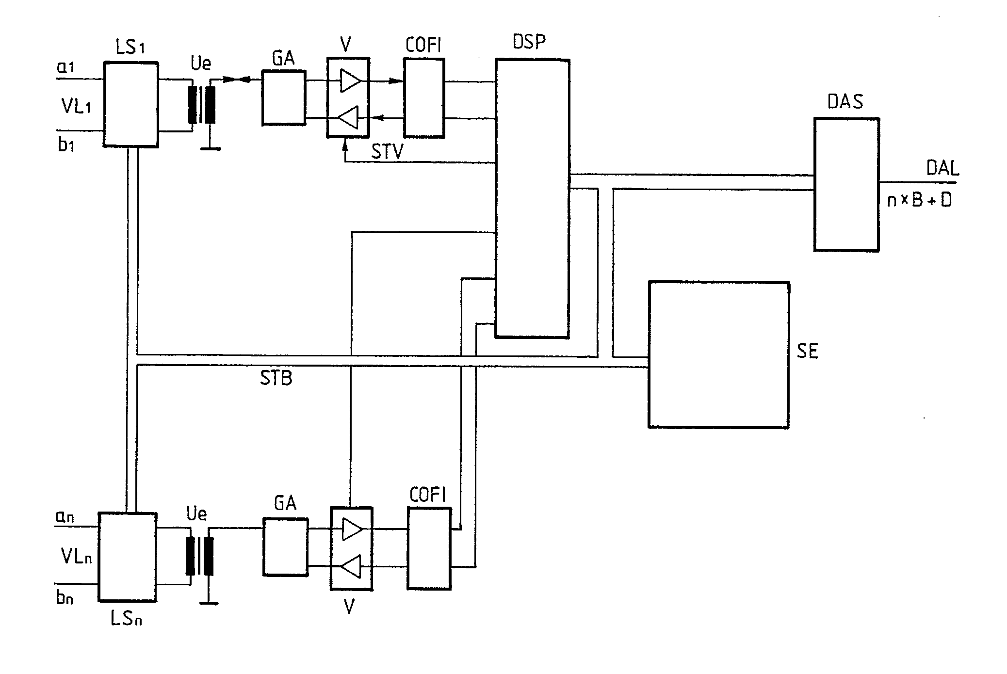
Description
Die Erfindung betrifft eine Schaltungsanordnung zur Signal - und Informationsumsetzung zwischen analog betriebenen Verbindungsleitungen und digital betriebenen Anschlußorganen in Kommunikations-Vermittlungsanlagen nach dem Oberbegriff des Patentanspruchs 1.The invention relates to a circuit arrangement for converting signals and information between analog operated connection lines and digitally operated connection elements in communication switching systems according to the preamble of claim 1.
Ein Verfahren zur Steuerung von Schaltkennzeichen und Schaltzuständen auf Verbindungsleitungen ist aus der DE-AS 29 19 617 bekannt. Dort wird eine dezentrale Steuerung beschrieben, die für mehrere Verbindungsleitungen zuständig ist und außerhalb des Sprachfrequenzbandes liegende Schaltkennzeichen steuert, die über die Verbindungsleitung zu empfangen und zu senden sind. Diese periphere Steuereinrichtung arbeitet mit einer Abtasteinrichtung und Speichern zusammen, wo die jeweiligen Verbindungszustände und die Eigenschaften der Verbindungsleitungen abgelegt sind. Das Steuern von zu sendenden Tonsignalen und das Auswerten von empfangenen Tonfrequenzen kann von einer derartigen Steuereinrichtung nicht durchgeführt werden.A method for controlling switching indicators and switching states on connecting lines is known from DE-AS 29 19 617. A decentralized control is described there, which is responsible for several connecting lines and controls switching indicators lying outside the voice frequency band, which are to be received and sent via the connecting line. This peripheral control device works together with a scanning device and memories, where the respective connection states and the properties of the connection lines are stored. The control of sound signals to be transmitted and the evaluation of received sound frequencies can be done by one such control device can not be performed.
Aus der DE-PS 30 14 572 ist eine Schaltungsanordnung zum Senden von Niederfrequenzsignalen auf Verbindungsleitungen in Fernsprechvermittlungsanlagen bekannt. Es sind matrixförmig aufgebaute Koppelbausteine vorgesehen, womit zentral erzeugte, im Sprachfrequenzband liegende Signale auf die Verbindungsleitung geschaltet werden. Hierfür ist jeweils eine dezentrale Steuerung vorgesehen, die für mehrere Verbindungsleitungen zuständig ist. Außerhalb des Sprachfrequenzbandes liegende Schaltkennzeichen lassen sich mit dieser Schaltungsanordnung nicht steuern.From DE-PS 30 14 572 a circuit arrangement for transmitting low frequency signals on connecting lines in telephone exchanges is known. Coupling modules with a matrix structure are provided, with which centrally generated signals in the voice frequency band are switched to the connecting line. A decentralized controller is responsible for this, which is responsible for several connecting lines. Switching indicators lying outside the speech frequency band cannot be controlled with this circuit arrangement.
Die Aufgabe der Erfindung besteht darin, eine Schaltungsanordnung anzugeben, womit alle auf einer Verbindungsleitung zu empfangenden und zu sendenden Signale, Kennzeichen und Nutzinformationen durch eine einzige dezentrale Steuereinrichtung so umgesetzt werden können, daß eine analog betriebene Verbindungsleitung mit einem digital betriebenen Anschlußorgan verbunden werden kann.The object of the invention is to provide a circuit arrangement with which all signals to be received and transmitted on a connecting line, identifiers and useful information can be implemented by a single decentralized control device in such a way that an analog operated connecting line can be connected to a digitally operated connecting element.
Zur Lösung dieser Aufgabe ist eine Merkmalskombination vorgesehen, wie sie im Patentanspruch 1 angegeben ist.To achieve this object, a combination of features is provided, as specified in claim 1.
Damit wird in vorteilhafter Weise erreicht, daß Vermittlungsanlagen unterschiedlicher Betriebsart miteinander verbunden werden können. Wenn eine analog betriebene Verbindungsleitung mit einem digital betriebenen Anschlußorgan verbunden werden kann, so bedeutet dies, daß nach diesem Schaltungsprinzip auch eine digital betriebene Verbindungsleitung mit einem analog betriebenen Anschlußorgan zusammengeschaltet werden kann. Da die dezentrale Steuereinrichtung und der digitale Signalprozessor nur jeweils für wenige Leitungen zuständig ist, können individuelle Anpassungen so vorgesehen werden, wie sie für den jeweiligen Leitungstyp optimal sind. In den Unteransprüchen sind zweckmäßige Weiterbildungen der Erfindung angegeben.This advantageously ensures that switching systems of different operating modes can be connected to one another. If an analog connection line can be connected to a digital connection element, this means that, according to this circuit principle, a digital connection line can also be connected to an analog connection element. Since the decentralized control device and the digital signal processor are only responsible for a few lines, individual adaptations can be provided in such a way that they are optimal for the respective line type. Advantageous developments of the invention are specified in the subclaims.
Ein Ausführungsbeispiel der Erfindung wird nachfolgend anhand einer Zeichnung näher erläutert.An embodiment of the invention is explained below with reference to a drawing.
In der Zeichnung ist dargestellt, wie analog betriebene Verbindungsleitungen VL1 - VLn mit ihren Adern a1/b1, bzw. an/bn zunächst über Leitungsschnittstellen LS1, LSn geführt und mit Übertragern UE abgeschlossen sind. Die Leitungsschnittstellen LS sind über ein Steuerleitungsbündel STB direkt mit einer peripheren Steuereinrichtung SE verbunden, die für mehrere Verbindungsleitungen zuständig ist. In den Leitungsschnittstellen LS befinden sich Sende- und Empfangseinrichtungen für alle Signale und Kennzeichen, die außerhalb des Sprachfrequenzbandes auszutauschen sind. Dabei handelt es sich um Gleichstromsignale, also um das Bilden und Unterbrechen von Gleichstromschleifen, so wie das An- und Abschalten von Gleichspannungen und von niederfrequenten Wechselspannungen, die als Anruf- und/oder Belegungssignal dienen.The drawing shows how analog operated connecting lines VL1 - VLn with their wires a1 / b1, or an / bn are initially routed via line interfaces LS1, LSn and terminated with transmitters UE. The line interfaces LS are connected via a control line bundle STB directly to a peripheral control device SE which is responsible for several connecting lines. In the line interfaces LS there are transmitting and receiving devices for all signals and labels which are to be exchanged outside the voice frequency band. These are direct current signals, that is to say the formation and interruption of direct current loops, such as the switching on and off of direct voltages and of low-frequency alternating voltages, which serve as a call and / or occupancy signal.
Der Sprechweg ist jeweils vom Übertrager Ue ausgehend zu einer Gabelschaltung GA geführt und verläuft über eine Verstärkeranordnung V zu den Wandlerschaltungen COFI, wo in bekannter Weise eine Analog- Digital-Wandlung, bzw. eine Digital-Analog-Wandlung der Sprachsignale stattfindet. Eine entsprechende Wandlung geschieht auch mit Signalisierungskennzeichen, welche als Töne über die Verbindungsleitung VL gesendet und empfangen werden. Die digitalen Eingänge und Ausgänge der Wandlerschaltungen COFI sind mit entsprechenden Ausgängen und Eingängen des digitalen Signalprozessors DSP verbunden.The speech path is in each case led from the transmitter Ue to a hybrid circuit GA and runs via an amplifier arrangement V to the converter circuits COFI, where an analog-digital conversion or a digital-analog conversion of the speech signals takes place in a known manner. A corresponding conversion also takes place with signaling indicators which are sent and received as tones via the connecting line VL. The digital inputs and outputs of the converter circuits COFI are connected to corresponding outputs and inputs of the digital signal processor DSP.
Ein gemeinsames Steuerleitungsbündel STB verbindet den digitalen Signalprozessor DSP mit der Steuereinrichtung SE, den Leitungsschnittstellen LS und einer digitalen Abschlußschnittstelle DAS, von wo aus eine digital betriebene Anschlußleitung DAL zu einem Anschlußorgan führt. Diese digitale Anschlußleitung DAL kann sehr kurz sein, wenn das digitale Anschlußorgan sich in der gleichen Vermittlungsanlage oder sogar innerhalb der gleichen Baugruppe befindet, wie die zur analog betriebenen Verbindungsleitung VL gehörende Übertragung, also der hier beschriebenen Schaltungsanordnung.A common control line bundle STB connects the digital signal processor DSP to the control device SE, the line interfaces LS and a digital termination interface DAS, from where a digitally operated connection line DAL leads to a connection element. This digital connection line DAL can be very short if the digital connection element is located in the same switching system or even within the same module as the transmission belonging to the analog connection line VL, ie the circuit arrangement described here.
Anhand von einigen Funktionsbeispielen soll nun die Arbeitsweise der gesamten Schaltungsanordnung beschrieben werden.The functioning of the entire circuit arrangement will now be described using a few functional examples.
Wenn über die analoge Verbindungsleitung VL ein Belegungs- oder Anrufsignal eintrifft, so wird dies von der zuständigen Leitungsschnittstelle LS zunächst erkannt und über das Steuerleitungsbündel STB zur Steuereinrichtung SE gemeldet. Daraufhin wird eine digitale Meldung erzeugt, und die digitale Abschlußschaltung DAS wird beauftragt, im Rahmen des Signalisierungskanals D eine Belegungsmeldung zum digitalen Anschlußorgan zu senden. Außerdem wird der digitale Signalprozessor aktiviert, so daß er in der Lage ist, über die Verbindungsleitung VL eintreffende Tonfrequenzsignale zu empfangen und auszuwerten. Wenn es sich dabei um tonfrequente Wahlinformation handelt, so wird diese ziffernweise vom digitalen Signalprozessor DSP erkannt, und es werden jeweils in Zusammenarbeit mit der Steuereinrichtung SE Signalisierungsmeldungen zusammengestellt, welche über die digitale Abschlußschnittstelle DAS zum digitalen Anschlußorgan gelangen.If an occupancy or call signal arrives via the analog connecting line VL, this is first recognized by the line interface LS responsible and reported to the control device SE via the control line bundle STB. A digital message is then generated and the digital termination circuit DAS is instructed to send an occupancy message to the digital connection element in the context of the signaling channel D. In addition, the digital signal processor activated so that it is able to receive and evaluate incoming audio frequency signals via the connecting line VL. If it is tone-frequency dialing information, this is recognized digit by digit by the digital signal processor DSP, and signaling messages are compiled in cooperation with the control device SE, which arrive at the digital connection element via the digital termination interface DAS.
Wenn die digitale Vermittlungsanlage den Zustand eines gewünschten Teilnehmeranschlusses überprüft hat, so werden im Signalisierungskanal D entsprechende Meldungen empfangen, welche von der digitalen Abschlußschnittstelle DAS empfangen und an die Steuereinrichtung SE weitergegeben werden. Daraufhin wird der Signalprozessor DSP beauftragt, entsprechende Tonfrequenzen digital zu generieren, so daß über die Wandlerschaltungen COFI ein Tonfrequenzsignal als Frei- oder Besetztzeichen abgegeben wird.When the digital switching system has checked the state of a desired subscriber line, appropriate messages are received in the signaling channel D, which messages are received by the digital termination interface DAS and passed on to the control device SE. Thereupon the signal processor DSP is commissioned to generate corresponding audio frequencies digitally, so that an audio frequency signal is given as a free or busy signal via the converter circuits COFI.
Wenn der gewünschte Teilnehmer der digitalen Vermittlungsanlage frei ist und sich meldet, so empfängt die digitale Abschlußschnittstelle DAS ein entsprechendes Signal im Signalisierungskanal D. Daraufhin wird die Steuereinrichtung SE angereizt, so daß der Gesprächszustand eingestellt wird, wobei ein entsprechendes Kriterium je nach Ausführung der Verbindungsleitung VL über die Leitungsschnittstelle LS ausgesendet wird. Die im Gesprächszustand auszutauschenden Nutzsignale werden in den Wandlerschaltungen COFI Analog-Digital, bzw. Digital-Analog gewandelt und durchlaufen den Signalprozessor DSP. Die digitalen Signale werden zwischen dem Signalprozessor DSP und der Abschlußschnittstelle DAS ausgetauscht und in beiden Richtungen über die digitale Anschlußleitung DAL in einem Nutzdatenkanal B übertragen. In diesem Zustand ist der digitale Signalprozessor DSP in der Lage, zu erkennen, wenn über die analoge Verbindungsleitung VL Signalisierungskennzeichen in Form von Tonfrequenzen einlaufen. Außerdem sind in der Leitungsschnittstelle LS Empfängerschaltungen in Bereitschaft, so daß ein Gleichstromsignal erkannt werden kann, welches beispielsweise die Beendigung einer Gesprächsverbindung signalisiert. In diesem Fall wird in Zusammenarbeit mit der Steuereinrichtung SE ein Kennzeichen erzeugt, welches in der für digitale Anschlußorgane üblichen Form im Rahmen des Signalisierungskanals D zur digitalen Anschlußleitung DAL ausgesendet wird.If the desired subscriber to the digital switching system is free and answers, the digital termination interface DAS receives a corresponding signal in the signaling channel D. The control device SE is then stimulated so that the call state is set, a corresponding criterion depending on the design of the connecting line VL is transmitted via the line interface LS. The useful signals to be exchanged in the conversation state are converted in the converter circuits COFI analog-digital or digital-analog and pass through the signal processor DSP. The digital signals are exchanged between the signal processor DSP and the termination interface DAS and transmitted in both directions via the digital connection line DAL in a user data channel B. In this state, the digital signal processor DSP is able to recognize if signaling marks in the form of sound frequencies arrive via the analog connecting line VL. In addition, receiver circuits are on standby in the line interface LS, so that a direct current signal can be recognized which signals, for example, the termination of a call connection. In this case, an identifier is generated in cooperation with the control device SE, which is transmitted in the form customary for digital connection elements in the context of the signaling channel D to the digital connection line DAL.
Eine von der digitalen Vermittlungsanlage aus aufgebaute Verbindung, welche als gehende Belegung der Verbindungsleitung VL ausgeführt werden soll, wird daran erkannt, daß von der digitalen Abschlußschnittstelle DAS über den Signalisierungskanal D eine entsprechende Meldung empfangen wird. Diese Meldung wird zur Steuereinrichtung SE weitergegeben, womit ein Schaltbefehl erzeugt wird, der über das Steuerleitungsbündel STB zur Leitungsschnittstelle LS gegeben wird. Von dort aus wird ein Belegungskriterium gebildet, welches beispielsweise in Form der Bildung einer Gleichstromschleife ausgesendet wird. Der Signalprozessor DSP wird in Empfangsbereitschaft versetzt, so daß aufgrund des Belegungskennzeichens einlaufende Wahlaufforderungssignale erkannt werden können. Über die analoge Verbindungsleitung VL einlaufende Antwort- oder Quittungssignale werden je nach ihrer Art entweder von der Leitungsschnittstelle LS oder vom digitalen Signalprozessor DSP erkannt.A connection established from the digital switching system, which is to be implemented as outgoing occupancy of the connecting line VL, is recognized by the fact that a corresponding message is received by the digital termination interface DAS via the signaling channel D. This message is passed on to the control device SE, with which a switching command is generated which is sent to the line interface LS via the control line bundle STB. From there, an occupancy criterion is formed, which is sent out, for example, in the form of a direct current loop. The signal processor DSP is put on standby to receive, so that incoming request signals can be recognized on the basis of the occupancy indicator. Answer or acknowledgment signals arriving via the analog connecting line VL are recognized either by the line interface LS or by the digital signal processor DSP, depending on their type.
Die in diesem Verbindungszustand über die Verbindungsleitung VL empfangenen Kennzeichen gelangen in entsprechend umgewandelter Befehlsform zur Steuereinrichtung SE, welche die digitale Abschlußschnittstelle DAS veranlaßt, eine entsprechende Signalisierungsmeldung im Signalisierungkanal D über die digitale Anschlußleitung DAL abzusenden. Die bei einer abgehenden Verbindung notwendigen Wahlinformationen werden über den Signalisierungskanal D empfangen und von der digitalen Abschlußschnittstelle zur Steuereinrichtung SE weitergegeben. Den Eigenschaften der Verbindungsleitung VL entsprechend werden daraus entweder von der Leitungsschnittstelle LS Gleichstromunterbrechungen in Impulsform erzeugt, oder es werden vom digitalen Signalprozessor DSP tonfrequente Wahlsignale nach dem Mehrfrequenzverfahren MFV generiert, welche analog gewandelt über den Sprechweg ausgesendet werden. Auch die nach dem Beendigen des Wahlvorgangs über die analoge Verbindungsleitung VL einlaufenden Kriterien werden je nach ihrer Art entweder von der Leitungsschnittstelle LS oder vom Signalprozessor DSP empfangen und über das Steuerleitungsbündel STB zur Steuereinrichtung SE weitergereicht. Daraufhin wird die digitale Abschlußschnittstelle DAS veranlaßt, das jeweils entsprechende Signalisierungswort über die digitale Anschlußleitung DAL auszusenden. Wenn auf diese Weise von der digitalen Verbindungsleitung VL ein Meldekriterium empfangen worden ist, so kommt die Gesprächsverbindung zustande.The identifiers received in this connection state via the connecting line VL arrive in a correspondingly converted command form at the control device SE, which causes the digital termination interface DAS to send a corresponding signaling message in the signaling channel D via the digital connecting line DAL. The dialing information required for an outgoing connection is received via the signaling channel D and passed on from the digital termination interface to the control device SE. According to the properties of the connecting line VL, DC line interruptions are generated in pulse form from the line interface LS, or tone-frequency selection signals are generated by the digital signal processor DSP using the multifrequency method MFV, which are transmitted in an analogue manner via the speech path. The criteria arriving after the termination of the dialing process via the analog connecting line VL are also received, depending on their type, either by the line interface LS or by the signal processor DSP and passed on to the control device SE via the control line bundle STB. The digital termination interface DAS is then caused to send out the corresponding signaling word via the digital connecting line DAL. If a notification criterion has been received in this way from the digital connecting line VL, the call is established.
Während einer bestehenden Gesprächsverbindung ist der digitale Signalprozessor DSP so eingestellt, daß er erkennt, welcher Anteil des jeweils gesendeten Nutzsignals von der Gabelschaltung GA durch Reflektion zurück übertragen wird. Daraufhin wird innerhalb des Signalprozessors DSP eine Kompensation wirksam, so daß die Funktion einer adaptiven Gabel erreicht wird.During an existing call, the digital signal processor DSP is set in such a way that it recognizes which portion of the useful signal transmitted in each case is transmitted back from the hybrid circuit GA by reflection. Thereupon a compensation takes effect within the signal processor DSP, so that the function of an adaptive fork is achieved.
Der Empfangspegel des ankommenden digitalisierten Nutzsignals wird jeweils bewertet und kann den Erfordernissen entsprechend so verstärkt werden, daß bei der Digitalisierung ein entsprechend höherer Pegel entsteht. In umgekehrter Richtung kann vom Signalprozessor DSP aus der Sendeverstärker innerhalb der Verstärkeranordnung V so eingestellt werden, daß ein für die Verbindungsleitung VL vorgegebener Pegel erreicht wird. Hierzu sind zwischen den Signalprozessor DSP und der Verstärkeranordnung V verlaufende Steuerleitungen STV vorgesehen.The received level of the incoming digitized useful signal is evaluated in each case and can be amplified according to the requirements so that a correspondingly higher level arises during digitization. In the opposite direction, the signal processor DSP can set the transmission amplifier within the amplifier arrangement V such that a predetermined level for the connecting line VL is reached. For this purpose, control lines STV are provided between the signal processor DSP and the amplifier arrangement V.
Je nach Anzahl der Verbindungsleitungen VL1 - VLn, die einer Steuereinrichtung SE und einem Signalprozessor DSP zugeordnet sind, werden durch die digitale Abschlußschnittstelle DAS entsprechend viele Nutzdatenkanäle B gebildet. Im allgemeinen wird ein Signalisierungskanal D genügen, um das Verkehrsaufkommen von mehreren Verbindungsleitungen VL zu bewältigen. Die Anzahl der Nutzdatenkanäle B und der Signalisierungskanäle D richten sich auch danach, welche Art von digitalem Anschlußorgan in der digitalen Vermittlungsanlage vorgesehen ist. Falls aufgrund der Anzahl von Verbindungsleitungen VL mehr Nutzdatenkanäle B gebildet werden müssen, als auf einer digitalen Anschlußleitung DAL wegen des Typs von Anschlußorgan in der digitalen Vermittlungsanlage unterzubringen sind, so ist es auch möglich, an die digitale Abschlußschnittstelle DAS mehrere digitale Anschlußleitungen DAL anzuschließen.Depending on the number of connecting lines VL1-VLn, which are assigned to a control device SE and a signal processor DSP, a corresponding number of useful data channels B are formed by the digital termination interface DAS. In general, one signaling channel D will suffice to handle the traffic volume of several connecting lines VL. The number of user data channels B and the signaling channels D also depend on what type of digital connection element is provided in the digital switching system. If, due to the number of connecting lines VL, more user data channels B have to be formed than can be accommodated on a digital connecting line DAL due to the type of connecting element in the digital switching system, it is also possible to connect several digital connecting lines DAL to the digital termination interface DAS.
Claims (7)
dadurch gekennzeichnet,
daß für die außerhalb des Sprachfrequenzbandes auszutauschenden Schaltkriterien und Kennzeichen Leitungsschnittstellen (LS) vorgesehen sind, welche direkt mit der zuständigen dezentralen Steuereinrichtung (SE) verbunden sind,
daß für die innerhalb des Sprachfrequenzbandes auszutauschenden Kennzeichen ein digitaler Signalprozessor (DSP) über eine Gabelschaltung (GA) und Wandlerschaltungen (COFI) in den Sprechweg eingeschleift ist, welcher mit der Steuereinrichtung (SE) zusammenarbeitet,
und daß die Steuereinrichtung (SE) mit Hilfe des Signalprozessors (DSP) eine digitale Abschlußschnittstelle (DAS) so ansteuert, daß Nutzkanäle (B) und mindestens ein Signalisierungskanal (D) gebildet werden.Circuit arrangement for signal and information conversion between analog operated connection lines and digitally operated connection elements in communication switching systems, with decentralized control devices being provided in order to process and forward the switching criteria and characteristics to be received and transmitted on the analog operated connection line inside and outside the voice frequency band ,
characterized,
that for the switching criteria and markings to be exchanged outside the voice frequency band, line interfaces (LS) are provided, which directly with the responsible decentralized control device (SE) are connected,
that for the characteristics to be exchanged within the voice frequency band, a digital signal processor (DSP) via a hook-up circuit (GA) and converter circuits (COFI) is looped into the speech path, which works together with the control device (SE),
and that the control device (SE) controls a digital termination interface (DAS) with the aid of the signal processor (DSP) such that useful channels (B) and at least one signaling channel (D) are formed.
dadurch gekennzeichnet,
daß die auf den Sprechweg von der analog betriebenen Verbindungsleitung (VL) ankommenden Hörtöne und tonfrequente Wahlinformationen vom Signalprozessor (DSP) empfangen und ausgewertet werden, und über ein Steuerleitungsbündel (STB) zur Steuereinrichtung (SE) gelangen, wo sie für die Abschlußschnittstelle (DAS) umgesetzt werden.Circuit arrangement according to claim 1,
characterized,
that the ringing tones and tone-frequency dialing information arriving on the speech path from the analog operated connection line (VL) are received and evaluated by the signal processor (DSP) and reach the control device (SE) via a control line bundle (STB), where they are used for the termination interface (DAS) be implemented.
dadurch gekennzeichnet,
daß die auf dem Sprechweg zur Verbindungsleitung (VL) zu sendenden Hörtöne und die Wahlinformationen vom Signalprozessor (DSP) in digitaler Form generiert werden aufgrund von Einstellbefehlen, die von der Steuereinrichtung (SE) erzeugt werden, wenn über die Abschlußschnittstelle (DAS) entsprechende Kriterien empfangen werden.Circuit arrangement according to claim 1,
characterized,
that the hearing tones to be sent on the speech path to the connecting line (VL) and the dialing information are generated by the signal processor (DSP) in digital form on the basis of setting commands which are generated by the control device (SE) when corresponding criteria are received via the termination interface (DAS) will.
dadurch gekennzeichnet,
daß beim Senden von Tonsignalen sowohl einfache Hörtöne oder Hörtonfolgen als auch Musikstücke und/oder Ansagen möglich sind, deren Strukturen parametrisch beschrieben innerhalb des Signalprozessors (DSP) abgelegt sind.Circuit arrangement according to claim 3,
characterized,
that simple audio tones or audio tone sequences as well as pieces of music and / or announcements are possible when sending audio signals, the structures of which are stored parametrically described within the signal processor (DSP).
dadurch gekennzeichnet,
daß der Signalprozessor (DSP) das von einem gesendeten Signal stammende reflektierte Signal kompensiert und damit die Funktion einer adaptiven Gabelschaltung (GA) digital nachbildet.Circuit arrangement according to claim 1,
characterized,
that the signal processor (DSP) compensates for the reflected signal originating from a transmitted signal and thus digitally simulates the function of an adaptive hybrid circuit (GA).
dadurch gekennzeichnet,
daß nach erfolgter Einstellung der Gabelanpassung durch den Signalprozessor (DSP) eine Pegelbewertung eines empfangenen Signals stattfindet und ein Steuerkriterium (ST) gebildet wird, womit Verstärker, (V) gesteuert werden, die zwischen der Gabelschaltung (GA) und den Wandlerschaltungen (COFI) angeordnet sind.Circuit arrangement according to claim 5,
characterized,
that after adjustment of the fork adjustment by the signal processor (DSP) a level evaluation of a received signal takes place and a control criterion (ST) is formed, with which amplifiers (V) are controlled, which are arranged between the hybrid circuit (GA) and the converter circuits (COFI) are.
dadurch gekennzeichnet,
daß der Pegel eines zu sendenden Signals durch Programmierung des Signalprozessors (DSP) auf genormte Werte einstellbar ist.Circuit arrangement according to claim 1,
characterized,
that the level of a signal to be sent can be adjusted to standardized values by programming the signal processor (DSP).
Applications Claiming Priority (2)
| Application Number | Priority Date | Filing Date | Title |
|---|---|---|---|
| DE4008450A DE4008450A1 (en) | 1990-03-16 | 1990-03-16 | CIRCUIT ARRANGEMENT FOR SIGNAL AND INFORMATION CONVERSION BETWEEN ANALOG-OPERATED CONNECTION LINES AND DIGITALLY-OPERATED CONNECTING BODIES IN COMMUNICATION SWITCHING SYSTEMS |
| DE4008450 | 1990-03-16 |
Publications (2)
| Publication Number | Publication Date |
|---|---|
| EP0446884A2 true EP0446884A2 (en) | 1991-09-18 |
| EP0446884A3 EP0446884A3 (en) | 1992-10-14 |
Family
ID=6402368
Family Applications (1)
| Application Number | Title | Priority Date | Filing Date |
|---|---|---|---|
| EP19910103814 Withdrawn EP0446884A3 (en) | 1990-03-16 | 1991-03-13 | Circuit arrangement for conversion of signalling and information between analog trunks and digital line circuits in a communications switch exchange |
Country Status (3)
| Country | Link |
|---|---|
| US (1) | US5289538A (en) |
| EP (1) | EP0446884A3 (en) |
| DE (1) | DE4008450A1 (en) |
Families Citing this family (11)
| Publication number | Priority date | Publication date | Assignee | Title |
|---|---|---|---|---|
| US5448635A (en) * | 1993-06-30 | 1995-09-05 | International Business Machines Corporation | Wiring scheme and network adapter with digital and analog outputs to allow old pots coexistence with ISDN |
| USRE38596E1 (en) * | 1994-06-27 | 2004-09-21 | International Business Machines Corporation | Methods for performing intelligent network services with an ISDN network terminator located at a subscriber's premise |
| CA2148384C (en) * | 1994-06-27 | 2003-03-18 | Charles Clifford Hallock | Methods for performing intelligent network services with an isdn network terminator located at a subscriber's premise |
| US6343126B1 (en) | 1996-03-27 | 2002-01-29 | Hello Direct, Inc. | Method and apparatus for interfacing analog telephone apparatus to a digital, analog or hybrid telephone switching system |
| US5912964A (en) * | 1996-03-27 | 1999-06-15 | Hello Direct, Inc. | Adaptive telephone handset interface |
| US5892823A (en) | 1996-03-27 | 1999-04-06 | Hello Direct, Inc. | Smart interface technology |
| US5848150A (en) * | 1997-02-26 | 1998-12-08 | Paradyne Corporation | Passive distributed filter system and method |
| JP2001506831A (en) * | 1996-12-17 | 2001-05-22 | パラダイン コーポレイション | Passive distributed filter system and method |
| DE19733250A1 (en) * | 1997-08-01 | 1999-02-04 | Deutsche Telephonwerk Kabel | Circuit arrangement for a network termination unit |
| US7031454B1 (en) | 1997-11-06 | 2006-04-18 | Hello Direct, Inc. | Method and apparatus for interfacing telephone apparatus to a digital, analog or hybrid telephone switching system |
| US6573729B1 (en) * | 2000-08-28 | 2003-06-03 | 3Com Corporation | Systems and methods for impedance synthesis |
Family Cites Families (16)
| Publication number | Priority date | Publication date | Assignee | Title |
|---|---|---|---|---|
| GB1588220A (en) * | 1977-09-12 | 1981-04-15 | Post Office | Digital switching of electronic signals |
| US4110560A (en) * | 1977-11-23 | 1978-08-29 | Gte Sylvania Incorporated | Communication apparatus |
| DE2919617C3 (en) * | 1979-05-16 | 1982-01-07 | Telefonbau Und Normalzeit Gmbh, 6000 Frankfurt | Method for controlling switching indicators and switching states on connecting lines of telecommunications, in particular telephone switching systems |
| US4228536A (en) * | 1979-05-29 | 1980-10-14 | Redcom Laboratories, Inc. | Time division digital communication system |
| US4270027A (en) * | 1979-11-28 | 1981-05-26 | International Telephone And Telegraph Corporation | Telephone subscriber line unit with sigma-delta digital to analog converter |
| DE3014572C2 (en) * | 1980-04-16 | 1982-12-09 | Telefonbau Und Normalzeit Gmbh, 6000 Frankfurt | Circuit arrangement for sending low-frequency signals on connecting lines in telephone exchanges |
| US4456991A (en) * | 1981-09-18 | 1984-06-26 | International Telephone And Telegraph Corporation | Telephone line circuit and system |
| DE3220511C3 (en) * | 1982-06-01 | 1987-03-26 | Telefonbau Und Normalzeit Gmbh, 6000 Frankfurt | CIRCUIT ARRANGEMENT FOR A TELECOMMUNICATION SYSTEM WITH CONNECTION-INDIVIDUAL CABLE TRANSMISSIONS. |
| DE3306884A1 (en) * | 1983-02-26 | 1984-08-30 | Standard Elektrik Lorenz Ag, 7000 Stuttgart | Signalling detector for telephone PBX systems with direct dialling-in |
| US4623760A (en) * | 1983-10-28 | 1986-11-18 | At&T Bell Laboratories | Signaling protocol interface channel unit |
| DE3343646A1 (en) * | 1983-12-02 | 1985-06-13 | Standard Elektrik Lorenz Ag, 7000 Stuttgart | CIRCUIT ARRANGEMENT FOR DETECTING AND EVALUATING AC VOLTAGE SIGNALS ON OFF-LINE Veins |
| US4759059A (en) * | 1984-06-01 | 1988-07-19 | Christensen Larry B | Analog telephone circuit for digital telephone system |
| GB8528843D0 (en) * | 1985-11-22 | 1985-12-24 | British Telecomm | Codec |
| US4852160A (en) * | 1987-03-03 | 1989-07-25 | Kiko Frederick J | Channel unit interface circuit |
| EP0400394B1 (en) * | 1989-05-31 | 1996-08-14 | Siemens Aktiengesellschaft | Interface device |
| US5133006A (en) * | 1990-10-31 | 1992-07-21 | Seiscor Technologies Inc. | Combination interface circuit for coupling a digital loop carrier telephone system |
-
1990
- 1990-03-16 DE DE4008450A patent/DE4008450A1/en active Granted
-
1991
- 1991-03-13 EP EP19910103814 patent/EP0446884A3/en not_active Withdrawn
- 1991-03-14 US US07/669,487 patent/US5289538A/en not_active Expired - Fee Related
Also Published As
| Publication number | Publication date |
|---|---|
| DE4008450A1 (en) | 1991-09-19 |
| US5289538A (en) | 1994-02-22 |
| EP0446884A3 (en) | 1992-10-14 |
| DE4008450C2 (en) | 1992-05-27 |
Similar Documents
| Publication | Publication Date | Title |
|---|---|---|
| EP0446884A2 (en) | Circuit arrangement for conversion of signalling and information between analog trunks and digital line circuits in a communications switch exchange | |
| DE1199333B (en) | Circuit arrangement for telecommunications, in particular telephone switchboards, in which speech paths and special signal channels are used to establish a connection | |
| DE2758109A1 (en) | SYSTEM FOR MULTIPLE USE OF A TWO-WIRE SUBSCRIBER CONNECTION CABLE IN THE TELEPHONE SWITCHING NETWORK | |
| DE1512996B2 (en) | PROCEDURE FOR THE INDEPENDENT SETUP OF TELEPHONE CONNECTIONS FROM AND TO MOBILE RADIO PHONE STATIONS | |
| EP0006244B1 (en) | Telecommunication system | |
| EP0095675B1 (en) | Circuit for a telephone exchange with line junctors which are individually allocated to connections | |
| DE2103307A1 (en) | Circuit arrangement for entering data into unoccupied channels of a multiplex system | |
| DE2607489C3 (en) | Special telephone system with company lines | |
| EP0460404B1 (en) | Method for data transmission in communication exchanges | |
| DE2243580C3 (en) | Centrally controlled Multiptex private branch exchange | |
| EP0447935B1 (en) | Circuit arrangement for sending and receiving tone frequency signals on telephone lines | |
| EP0901268A2 (en) | Apparatus with a door station and a plurality of dwelling stations interconnected by a two wire bus | |
| EP0390976B1 (en) | Process for communication exchanges with audio frequency push-button dialing | |
| DE4125362C2 (en) | Arrangement for connecting analog communication terminals to digital subscriber line devices of a communication system | |
| DE3526708A1 (en) | Circuit arrangement for transmission of dialling information between communications exchanges within a communications network | |
| DE2828583A1 (en) | Telephone subscriber station for analogue and digital communications - has conventional facilities plus switching for digital transmissions | |
| DE2607493C3 (en) | Special telephone system with company management | |
| DE3123614C2 (en) | Method and circuit arrangement for the remote-controlled switching of subscriber lines to an announcement device | |
| DE10240810B3 (en) | Method and circuit arrangement for controlling a subscriber line interface circuit | |
| EP0553436B1 (en) | Method for testing the operation of transmission links for telecommunication signals | |
| CH674112A5 (en) | ||
| DE958665C (en) | Procedure for avoiding the idle state at the forks of four-wire waehlfernlinien with amplifiers | |
| DE4236046C1 (en) | Intercom system with centralised control - uses duplex amplifiers in connection path between calling and called speech stations with respective amplifier paths for each direction | |
| EP0058241B1 (en) | Method and circuit for the transmission of data signals and signalling information between data terminal equipment, which is interconnected through the exchanges of a telecommunication network | |
| EP0235529A2 (en) | Circuit arrangement for hands-free devices and devices with a receiving amplifier at telephone sets |
Legal Events
| Date | Code | Title | Description |
|---|---|---|---|
| PUAI | Public reference made under article 153(3) epc to a published international application that has entered the european phase |
Free format text: ORIGINAL CODE: 0009012 |
|
| AK | Designated contracting states |
Kind code of ref document: A2 Designated state(s): FR GB IT NL SE |
|
| PUAL | Search report despatched |
Free format text: ORIGINAL CODE: 0009013 |
|
| AK | Designated contracting states |
Kind code of ref document: A3 Designated state(s): FR GB IT NL SE |
|
| 17P | Request for examination filed |
Effective date: 19921109 |
|
| 17Q | First examination report despatched |
Effective date: 19931129 |
|
| STAA | Information on the status of an ep patent application or granted ep patent |
Free format text: STATUS: THE APPLICATION HAS BEEN WITHDRAWN |
|
| 18W | Application withdrawn |
Withdrawal date: 19940115 |