EP0447830B1 - Filter for liquids - Google Patents
Filter for liquids Download PDFInfo
- Publication number
- EP0447830B1 EP0447830B1 EP91102614A EP91102614A EP0447830B1 EP 0447830 B1 EP0447830 B1 EP 0447830B1 EP 91102614 A EP91102614 A EP 91102614A EP 91102614 A EP91102614 A EP 91102614A EP 0447830 B1 EP0447830 B1 EP 0447830B1
- Authority
- EP
- European Patent Office
- Prior art keywords
- filter
- filter housing
- end disc
- socket
- housing
- Prior art date
- Legal status (The legal status is an assumption and is not a legal conclusion. Google has not performed a legal analysis and makes no representation as to the accuracy of the status listed.)
- Expired - Lifetime
Links
Images
Classifications
-
- B—PERFORMING OPERATIONS; TRANSPORTING
- B01—PHYSICAL OR CHEMICAL PROCESSES OR APPARATUS IN GENERAL
- B01D—SEPARATION
- B01D27/00—Cartridge filters of the throw-away type
- B01D27/005—Making filter elements not provided for elsewhere
-
- B—PERFORMING OPERATIONS; TRANSPORTING
- B01—PHYSICAL OR CHEMICAL PROCESSES OR APPARATUS IN GENERAL
- B01D—SEPARATION
- B01D27/00—Cartridge filters of the throw-away type
- B01D27/04—Cartridge filters of the throw-away type with cartridges made of a piece of unitary material, e.g. filter paper
- B01D27/06—Cartridge filters of the throw-away type with cartridges made of a piece of unitary material, e.g. filter paper with corrugated, folded or wound material
-
- F—MECHANICAL ENGINEERING; LIGHTING; HEATING; WEAPONS; BLASTING
- F02—COMBUSTION ENGINES; HOT-GAS OR COMBUSTION-PRODUCT ENGINE PLANTS
- F02M—SUPPLYING COMBUSTION ENGINES IN GENERAL WITH COMBUSTIBLE MIXTURES OR CONSTITUENTS THEREOF
- F02M37/00—Apparatus or systems for feeding liquid fuel from storage containers to carburettors or fuel-injection apparatus; Arrangements for purifying liquid fuel specially adapted for, or arranged on, internal-combustion engines
- F02M37/22—Arrangements for purifying liquid fuel specially adapted for, or arranged on, internal-combustion engines, e.g. arrangements in the feeding system
- F02M37/32—Arrangements for purifying liquid fuel specially adapted for, or arranged on, internal-combustion engines, e.g. arrangements in the feeding system characterised by filters or filter arrangements
-
- B—PERFORMING OPERATIONS; TRANSPORTING
- B01—PHYSICAL OR CHEMICAL PROCESSES OR APPARATUS IN GENERAL
- B01D—SEPARATION
- B01D2201/00—Details relating to filtering apparatus
- B01D2201/34—Seals or gaskets for filtering elements
Definitions
- the invention relates to a filter for liquids, in particular for fuel or lubricating oil for an internal combustion engine, according to the preamble of claim 1.
- Such a fuel filter is known from DE-B 12 67 029.
- the end disk of the filter insert which is provided with a central recess, lies with its inner diameter against an annular connection piece of the filter housing.
- an additional ring seal is provided or the end disk is provided on its inner circumference with an upwardly directed ring flange, which brings about the sliding ring seal between the filter insert and the socket of the filter housing.
- the end disk which is in contact with a socket of the filter housing has on its inner circumference a sealing lip which is designed as an annular flange and which rests under internal stress on the socket of the filter housing. Another on the outer circumference the sealing lip attached to the end plate is supported under axially acting internal stress on the housing base.
- the object of the present invention is therefore to design such a filter in such a way that a permanent seal between the filter insert and the filter housing can be achieved with structurally simple and inexpensive means.
- an adequate seal between the filter insert and the filter housing is achieved through the use of a plastic that swells in liquids for the end plates.
- the sealing effect occurs in that the plastic of the end plate is prevented from expanding radially outwards during swelling, as a result of which the swelling also has an effect radially inward and leads to the desired tight fit on the central connector.
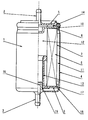
- a fuel filter 1 which can be connected to a fuel line (not shown) via connecting pieces 2, 3, consists of a filter housing 4 and a filter housing cover 5 made of aluminum, which are firmly connected to one another by welding.
- a paper filter insert 6 stored in the interior of the filter housing 4 comprises an annular, star-shaped folded paper band 7, which is plasticized with its ends in an upper 8 and a lower end plate 9 made of plastic.
- the upper, disk-shaped end disk 8 has cutouts 10 on its outer circumference so that the fuel supplied through the connecting piece 2 of the filter housing cover 5 reaches the tube space 11 of the fuel filter 1.
- ribs 13 projecting into the clean room 12 are formed on the lower end disk 9.
- a circumferential cam 14 is formed on the outside of the upper end plate 8.
- the lower end disk 9 is provided with a central recess and lies with its inner circumference 15 in a sealing manner against an annular connecting piece 16 of the filter housing 4.
- the lower end plate 9 lies with its outer circumference 17 under prestress on the inner wall of the filter housing 4, so that a secure seal between the filter insert 6 and the filter housing is ensured.
- semicircular recesses 18 are formed on the outer circumference 17 of the lower end disk 9, so that only the wall sections which have remained between these recesses 18 bear directly against the filter housing 4. As a result, in particular the forces occurring in the end plate when the plastic swells are better absorbed.
- a plastic which swells in the fuel in particular polypropylene, is used as the material for the end disks 8, 9, its swelling value being approximately 9%.
Description
Die Erfindung betrifft einen Filter für Flüssigkeiten, insbesondere für Kraftstoff oder Schmieröl für einen Verbrennungsmotor, nach dem Oberbegriff des Anspruchs 1.The invention relates to a filter for liquids, in particular for fuel or lubricating oil for an internal combustion engine, according to the preamble of claim 1.
Ein derartiger Brennstoffilter ist aus der DE-B 12 67 029 bekannt. Bei diesem Filter liegt die mit einer mittigen Aussparung versehene Endscheibe des Filtereinsatzes mit ihrem Innendurchmesser an einem ringförmigen Stutzen des Filtergehäuses an. Um den Filtereinsatz an dieser Stelle gegenüber dem Filtergehäuse abzudichten ist entweder eine zusätzliche Ringdichtung vorgesehen oder die Endscheibe an ihrem Innenumfang mit einem nach oben gerichteten Ringflansch versehen, der die gleitende Ringdichtung zwischen dem Filtereinsatz und dem Stutzen des Filtergehäuses bewirkt.Such a fuel filter is known from DE-B 12 67 029. With this filter, the end disk of the filter insert, which is provided with a central recess, lies with its inner diameter against an annular connection piece of the filter housing. In order to seal the filter insert at this point with respect to the filter housing, either an additional ring seal is provided or the end disk is provided on its inner circumference with an upwardly directed ring flange, which brings about the sliding ring seal between the filter insert and the socket of the filter housing.
Gemäß einem Ausführungsbeispiel in der DE-A 24 29 474 weist bei einer Filterpatrone die an einem Stutzen des Filtergehäuses anliegende Endscheibe auf ihrem inneren Umfang eine als Ringflansch ausgebildete Dichtlippe auf, die unter Eigenspannung am Stutzen des Filtergehäuses anliegt. Eine weitere am Außenumfang der Endscheibe angebrachte Dichtlippe stützt sich unter axial wirkender Eigenspannung am Gehäuseboden ab.According to an exemplary embodiment in DE-A 24 29 474, in the case of a filter cartridge, the end disk which is in contact with a socket of the filter housing has on its inner circumference a sealing lip which is designed as an annular flange and which rests under internal stress on the socket of the filter housing. Another on the outer circumference the sealing lip attached to the end plate is supported under axially acting internal stress on the housing base.
Nachteilig an diesen Ausführungen ist, daß entweder eine zusätzliche Dichtung vorgesehen werden muß, bzw., daß der an der Endscheibe vorgesehene Ringflansch nur ohne besondere Anpreßkraft an dem Stutzen des Filtergehäuses anliegt, wodurch eine gute und dauerhafte Dichtwirkung nicht gewährleistet ist.The disadvantage of these designs is that either an additional seal must be provided, or that the ring flange provided on the end plate only bears against the nozzle of the filter housing without any special contact pressure, as a result of which a good and permanent sealing effect is not guaranteed.
Aufgabe der vorliegenden Erfindung ist es daher, einen derartigen Filter so auszubilden, daß eine dauerhafte Abdichtung zwischen Filtereinsatz und Filtergehäuse mit konstruktiv einfachen und kostengünstigen Mitteln erreichbar ist.The object of the present invention is therefore to design such a filter in such a way that a permanent seal between the filter insert and the filter housing can be achieved with structurally simple and inexpensive means.
Gelöst wird diese Aufgabe durch eine Ausbildung des Filters nach den Merkmalen des kennzeichnenden Teils des Anspruchs 1.This object is achieved by designing the filter according to the features of the characterizing part of claim 1.
Mit einer derartigen Ausführung ist durch die Verwendung eines in Flüssigkeiten quellbaren Kunststoffes für die Endscheiben eine ausreichende Abdichtung zwischen Filtereinsatz und Filtergehäuse erreicht. Die Dichtwirkung tritt dabei dadurch ein, daß der Kunststoff der Endscheibe beim Aufquellen an einer Ausdehnung nach radial außen gehindert wird, wodurch sich das Quellen auch nach radial innen auswirkt und zu der dort gewünschten dichten Anlage an dem zentralen Stutzen führt.With such a design, an adequate seal between the filter insert and the filter housing is achieved through the use of a plastic that swells in liquids for the end plates. The sealing effect occurs in that the plastic of the end plate is prevented from expanding radially outwards during swelling, as a result of which the swelling also has an effect radially inward and leads to the desired tight fit on the central connector.
Vorteilhafte Ausgestaltungen nach der Erfindung sind in den Unteransprüchen enthalten.Advantageous embodiments according to the invention are contained in the subclaims.
Ein Ausführungsbeispiel ist in der Zeichnung dargestellt und wird nachfolgend im einzelnen beschrieben.An embodiment is shown in the drawing and will be described in detail below.
Ein Kraftstoffilter 1, der über Anschlußstutzen 2, 3 an eine Kraftstoffleitung (nicht gezeichnet) angeschlossen werden kann, besteht aus einem Filtergehäuse 4 und einem Filtergehäusedeckel 5 aus Aluminium, die durch Schweißen fest miteinander verbunden sind.A fuel filter 1, which can be connected to a fuel line (not shown) via connecting
Ein im Inneren des Filtergehäuses 4 gelagerter Papier-Filtereinsatz 6 umfaßt ein ringförmiges, sternförmig gefaltetes Papierband 7, das mit seinen Enden in einer oberen 8 und einer unteren Endscheibe 9 aus Kunststoff einplastifiziert ist. Die obere, scheibenfömig ausgebildete Endscheibe 8 weist an ihrem Außenumfang Aussparungen 10 auf, damit der durch den Anschlußstutzen 2 des Filtergehäusedeckels 5 zugeführte Kraftstoff in den Rohraum 11 des Kraftstoffilters 1 gelangt. Zur Abstützung des sternförmig gefalteten Papierbandes 7 sind an der unteren Endscheibe 9 in den Reinraum 12 ragende Rippen 13 angeformt. Zur Abstützung des Papier-Filtereinsatzes 6 an dem Filtergehäusedeckel 5 ist ein umlaufender Nocken 14 an der Außenseite der oberen Endscheibe 8 angeformt.A paper filter insert 6 stored in the interior of the filter housing 4 comprises an annular, star-shaped folded
Die untere Endscheibe 9 ist mit einer mittigen Ausnehmung versehen und liegt mit ihrem Innenumfang 15 dichtend an einem ringförmig umlaufenden Stutzen 16 des Filtergehäuses 4 an. Die untere Endscheibe 9 liegt mit ihrem Außenumfang 17 unter Vorspannung an der Innenwand des Filtergehäuses 4 an, so daß eine sichere Abdichtung zwischen Filtereinsatz 6 und Filtergehäuse gewährleistet ist. Im aufgezeigten Ausführungsbeispiel sind auf dem Außenumfang 17 der unteren Endscheibe 9 halbkreisförmig ausgebildete Ausnehmungen 18 angebracht, so daß nur die zwischen diesen Ausnehmungen 18 stehengebliebenen Wandabschnitte direkt am Filtergehäuse 4 anliegen. Hierdurch werden insbesondere die beim Quellen des Kunststoffes in der Endscheibe auftretenden Kräfte besser aufgenommen.The lower end disk 9 is provided with a central recess and lies with its
Als Werkstoff für die Endscheiben 8, 9 wird ein in dem Kraftstoff quellender Kunststoff, insbesondere Polypropylen verwendet, wobei dessen Quellwert ca. 9% beträgt.A plastic which swells in the fuel, in particular polypropylene, is used as the material for the
Mit einem derartigen Filter wird durch Verwendung eines in Flüssigkeiten quellbaren Kunststoffes für die Endscheiben des Filtereinsatzes, wobei die eine Endscheibe 9 einerseits mit ihrem Innenumfang 15 dichtend an dem Stutzen 16 des Filtergehäuses und andererseits mit ihrem Außenumfang 17 an der Innenwandung des Filtergehäuses abgestützt anliegt, auf konstruktiv einfache Weise eine dauerhafte Abdichtung zwischen Filtereinsatz 6 und Filtergehäuse 4 gewährleistet.With such a filter, the use of a plastic that swells in liquids for the end plates of the filter insert, one end plate 9, on the one hand, with its
Claims (4)
- Filter for liquids, in particular for fuel or lubricating oil for an internal combustion engine, with an annular filter element mounted in a filter housing, with at least one annular filter element end disc which radially on the inside is seated hermetically on a socket of the filter housing, characterised in that this at least one end disc (9) consists of synthetic material which swells up in the liquid and has a swelling value of 1 to 10% and radially externally bears over the entire periphery (17) substantially frictionally and positively on the filter housing (4) so that due to the radially acting forces occurring at the time of swelling-up of the material of the end disc (9), the inner periphery of the end disc (9) bears with an increased sealing action against the socket of the filter housing.
- Filter according to Claim 1, characterised in that on its outer periphery (17) the end disc (9) comprises recesses (18).
- Filter according to Claim 2, characterised in that the recesses (18) are constructed to be semicircular.
- Filter according to one of the preceding Claims, characterised in that the end discs (8, 9) consist of polypropylene as the synthetic material which is able to swell.
Applications Claiming Priority (2)
| Application Number | Priority Date | Filing Date | Title |
|---|---|---|---|
| DE4009344A DE4009344A1 (en) | 1990-03-23 | 1990-03-23 | FILTERS FOR LIQUIDS |
| DE4009344 | 1990-03-23 |
Publications (3)
| Publication Number | Publication Date |
|---|---|
| EP0447830A2 EP0447830A2 (en) | 1991-09-25 |
| EP0447830A3 EP0447830A3 (en) | 1992-02-19 |
| EP0447830B1 true EP0447830B1 (en) | 1994-05-11 |
Family
ID=6402887
Family Applications (1)
| Application Number | Title | Priority Date | Filing Date |
|---|---|---|---|
| EP91102614A Expired - Lifetime EP0447830B1 (en) | 1990-03-23 | 1991-02-22 | Filter for liquids |
Country Status (3)
| Country | Link |
|---|---|
| EP (1) | EP0447830B1 (en) |
| DE (2) | DE4009344A1 (en) |
| ES (1) | ES2055471T3 (en) |
Families Citing this family (6)
| Publication number | Priority date | Publication date | Assignee | Title |
|---|---|---|---|---|
| DE4020831A1 (en) * | 1990-06-29 | 1992-01-02 | Bosch Gmbh Robert | FILTER ELEMENT IN WINDING DESIGN |
| DE4226267A1 (en) * | 1992-08-08 | 1994-02-10 | Knecht Filterwerke Gmbh | Filters for liquids |
| DE4236490C1 (en) * | 1992-10-29 | 1994-05-19 | Stihl Maschf Andreas | Fuel suction head in tank - has plastics housing for filter element inserted through end opening |
| DE19520156A1 (en) * | 1995-06-01 | 1996-12-05 | Mann & Hummel Filter | Filters, in particular air filters for the intake air of an internal combustion engine |
| DE19646350C2 (en) * | 1996-11-09 | 2000-07-06 | Mahle Filtersysteme Gmbh | Liquid filters, in particular fuel filters for internal combustion engines |
| DE10106526A1 (en) * | 2001-02-13 | 2002-08-22 | Mann & Hummel Filter | Cylindrical filter cartridge with support tube |
Family Cites Families (7)
| Publication number | Priority date | Publication date | Assignee | Title |
|---|---|---|---|---|
| GB760736A (en) * | 1954-03-18 | 1956-11-07 | Aksel Myring | A filter for lubrication oil, benzine and fuel oil for internal combustion engines |
| FR1216783A (en) * | 1960-09-27 | 1960-04-27 | Fram Corp | Liquid filter |
| DE1833234U (en) * | 1960-09-30 | 1961-06-22 | Mann & Hummel Filter | DISPOSABLE FILTERS FOR LIQUIDS, IN PARTICULAR FOR THE LUBRICATION OIL OF COMBUSTION MACHINES. |
| US3217942A (en) * | 1962-03-20 | 1965-11-16 | Wix Corp | Filter unit |
| GB1033241A (en) * | 1964-01-03 | 1966-06-22 | Gen Motors Ltd | Fuel pumps |
| FR2268551B1 (en) * | 1974-04-24 | 1980-12-05 | Cfea | |
| DE3514778C1 (en) * | 1985-04-24 | 1986-08-14 | Knecht Filterwerke Gmbh, 7000 Stuttgart | Filter insert for a liquid filter |
-
1990
- 1990-03-23 DE DE4009344A patent/DE4009344A1/en not_active Withdrawn
-
1991
- 1991-02-22 DE DE59101592T patent/DE59101592D1/en not_active Expired - Lifetime
- 1991-02-22 EP EP91102614A patent/EP0447830B1/en not_active Expired - Lifetime
- 1991-02-22 ES ES91102614T patent/ES2055471T3/en not_active Expired - Lifetime
Also Published As
| Publication number | Publication date |
|---|---|
| DE59101592D1 (en) | 1994-06-16 |
| DE4009344A1 (en) | 1991-09-26 |
| EP0447830A2 (en) | 1991-09-25 |
| ES2055471T3 (en) | 1994-08-16 |
| EP0447830A3 (en) | 1992-02-19 |
Similar Documents
| Publication | Publication Date | Title |
|---|---|---|
| EP0423435B1 (en) | Air filter with radial sealing filter insert | |
| EP1177826B1 (en) | Replaceable filter cartridge with support member, liquid filter with that filter cartridge | |
| EP1191994B1 (en) | Air filter for an internal combustion engine | |
| DE3538589C2 (en) | ||
| EP0577660B1 (en) | Filter for liquids, in particular internal-combustion engine lubricant oils | |
| EP2813275B1 (en) | Use of a filter element in a filter system | |
| DE19752376A1 (en) | Filter, for liquids | |
| EP2207610B1 (en) | Liquid filter | |
| EP1163945B1 (en) | Cylindrical filter cartridge with supporting tube | |
| EP0951329A1 (en) | Filter, in particular for the lubricating oil of an internal combustion engine | |
| EP0559011B1 (en) | Ring filter element with the endwalls covered tightly by a sealing material in flat or film-like disposition | |
| DE4428139A1 (en) | Filter device | |
| DE202007012691U1 (en) | Cut filter | |
| DE19644646A1 (en) | Filters, in particular for filtering the lubricating oil of an internal combustion engine | |
| DE2007974A1 (en) | Filter arrangement | |
| EP4308807A1 (en) | Filter element and filter system | |
| DE102016005356A1 (en) | Filter element, in particular for gas filtration, and filter device | |
| EP0447830B1 (en) | Filter for liquids | |
| DE4330839C2 (en) | Filters for cleaning liquids | |
| EP1690582A1 (en) | Filter system | |
| EP0582949B1 (en) | Filter for liquids | |
| WO1998013121A1 (en) | Filter for liquids | |
| EP3341105B1 (en) | Fluid filter and filter insert for the same | |
| EP0528179B1 (en) | Liquid filter | |
| DE3625764C1 (en) | Liquid filter, in particular lubricating oil filter for internal combustion engines |
Legal Events
| Date | Code | Title | Description |
|---|---|---|---|
| PUAI | Public reference made under article 153(3) epc to a published international application that has entered the european phase |
Free format text: ORIGINAL CODE: 0009012 |
|
| AK | Designated contracting states |
Kind code of ref document: A2 Designated state(s): DE ES FR |
|
| PUAL | Search report despatched |
Free format text: ORIGINAL CODE: 0009013 |
|
| AK | Designated contracting states |
Kind code of ref document: A3 Designated state(s): DE ES FR |
|
| 17P | Request for examination filed |
Effective date: 19920402 |
|
| 17Q | First examination report despatched |
Effective date: 19930503 |
|
| GRAA | (expected) grant |
Free format text: ORIGINAL CODE: 0009210 |
|
| AK | Designated contracting states |
Kind code of ref document: B1 Designated state(s): DE ES FR |
|
| REF | Corresponds to: |
Ref document number: 59101592 Country of ref document: DE Date of ref document: 19940616 |
|
| ET | Fr: translation filed | ||
| REG | Reference to a national code |
Ref country code: ES Ref legal event code: FG2A Ref document number: 2055471 Country of ref document: ES Kind code of ref document: T3 |
|
| PLBI | Opposition filed |
Free format text: ORIGINAL CODE: 0009260 |
|
| 26 | Opposition filed |
Opponent name: A. KAYSER GMBH & CO. KG Effective date: 19950131 |
|
| PLBN | Opposition rejected |
Free format text: ORIGINAL CODE: 0009273 |
|
| STAA | Information on the status of an ep patent application or granted ep patent |
Free format text: STATUS: OPPOSITION REJECTED |
|
| 27O | Opposition rejected |
Effective date: 19951113 |
|
| PGFP | Annual fee paid to national office [announced via postgrant information from national office to epo] |
Ref country code: ES Payment date: 20020211 Year of fee payment: 12 |
|
| PG25 | Lapsed in a contracting state [announced via postgrant information from national office to epo] |
Ref country code: ES Free format text: LAPSE BECAUSE OF NON-PAYMENT OF DUE FEES Effective date: 20030224 |
|
| REG | Reference to a national code |
Ref country code: ES Ref legal event code: FD2A Effective date: 20030224 |
|
| PGFP | Annual fee paid to national office [announced via postgrant information from national office to epo] |
Ref country code: FR Payment date: 20100225 Year of fee payment: 20 |
|
| PGFP | Annual fee paid to national office [announced via postgrant information from national office to epo] |
Ref country code: DE Payment date: 20100308 Year of fee payment: 20 |
|
| REG | Reference to a national code |
Ref country code: DE Ref legal event code: R071 Ref document number: 59101592 Country of ref document: DE |
|
| PG25 | Lapsed in a contracting state [announced via postgrant information from national office to epo] |
Ref country code: DE Free format text: LAPSE BECAUSE OF EXPIRATION OF PROTECTION Effective date: 20110222 |