EP0447819A2 - Multileveled electronic assembly with cooling means - Google Patents
Multileveled electronic assembly with cooling means Download PDFInfo
- Publication number
- EP0447819A2 EP0447819A2 EP91102392A EP91102392A EP0447819A2 EP 0447819 A2 EP0447819 A2 EP 0447819A2 EP 91102392 A EP91102392 A EP 91102392A EP 91102392 A EP91102392 A EP 91102392A EP 0447819 A2 EP0447819 A2 EP 0447819A2
- Authority
- EP
- European Patent Office
- Prior art keywords
- fluid
- assembly
- assembly according
- cooling
- duct
- Prior art date
- Legal status (The legal status is an assumption and is not a legal conclusion. Google has not performed a legal analysis and makes no representation as to the accuracy of the status listed.)
- Granted
Links
Images


Classifications
-
- G—PHYSICS
- G06—COMPUTING; CALCULATING OR COUNTING
- G06F—ELECTRIC DIGITAL DATA PROCESSING
- G06F1/00—Details not covered by groups G06F3/00 - G06F13/00 and G06F21/00
- G06F1/16—Constructional details or arrangements
- G06F1/20—Cooling means
-
- H—ELECTRICITY
- H05—ELECTRIC TECHNIQUES NOT OTHERWISE PROVIDED FOR
- H05K—PRINTED CIRCUITS; CASINGS OR CONSTRUCTIONAL DETAILS OF ELECTRIC APPARATUS; MANUFACTURE OF ASSEMBLAGES OF ELECTRICAL COMPONENTS
- H05K7/00—Constructional details common to different types of electric apparatus
- H05K7/20—Modifications to facilitate cooling, ventilating, or heating
- H05K7/20709—Modifications to facilitate cooling, ventilating, or heating for server racks or cabinets; for data centers, e.g. 19-inch computer racks
- H05K7/20718—Forced ventilation of a gaseous coolant
- H05K7/20736—Forced ventilation of a gaseous coolant within cabinets for removing heat from server blades
Abstract
Description
- This invention relates to cooling systems for use in electronic assemblies and particularly for use in such assemblies as used in information handling systems (computers). The invention is also useable in such systems currently being referred to in the art as supercomputers.
- Effective removal of heat generated by various electronic components which form part of an electronic assembly such as a computer is critical in order for the assembly to operate in a satisfactory manner. In many of today's computers, circuit and component miniaturization efforts have successfully resulted in the reduction of the amount of heat generated by such circuit components and subcircuit assemblies. However, concurrent with such reduction in heat generation per component has been an increasing desire to significantly increase packaging densities, the overall result being that the total amount of heat being generated per unit area has not significantly decreased. And, in the case of supercomputers, wherein maximum densities are essential, extraordinarily high levels of heat generation are being experienced. By the term supercomputer as used herein is meant to define a high speed, high capacity information handling system wherein power levels within the range of about 50,000 to about 100,000 watts are utilized, such systems generating upwards of approximately 7,000 BTU's per minute of heat during normal operation. The processing capabilities of such systems may be within the range of about 150 to about 18,000 megaflops (millions of basic floating point operations per second). It is to be understood that the teachings of this invention are not limited to supercomputers as described above but that the cooling system as defined herein may be used satisfactorily in many various types of electronic assemblies, including computers having significantly less processing capabilities (e.g., about 5000 to 50,000 watts) than cited above. Equally significant, the invention may also find usage in information handling systems possessing greater capabilities than described for the supercomputers mentioned above, particularly if such computers are of the multileveled type having substrates and components located at separate levels within the computer's housing structure.
- Various techniques have been employed to provide cooling to electronic components within a computer, including forced air through the computer's console to the use of liquid or refrigerant filled cold bars or cold plate chassis members wherein such fluids as fluorocarbon products are circulated. Such liquids may be obtained having different boiling points, depending on the operational requirements of the system being cooled. Immersion cooling has also been employed in some known computer systems and is considered to have some advantages over regular air cooling due to higher heat transfer rates and the higher heat capacity of the liquid in comparison to that of a gas.
- In the case of forced air systems, hot spots have still resulted which in turn have required rather sophisticated console interior layouts and/or geometries of the system's components. On many occasions in such designs, the cabinet structure formed part of the air directional and containment means which meant that, once the cabinet's door was opened (e.g., to effect component or card repair and/or replacement), the effectiveness of the cooling means was substantially reduced. In cooling systems which utilize cooling bars and cold plate chassis members (e.g., wherein heat generated by components mounted on a circuit board or card is transmitted by convection and conduction to cold plates and then to cold bars, these refrigerant cooled bars possibly having some means for receiving the edges of the plates to which the cards may be mounted), such systems have proven insufficient for effectively removing heat in high density electronic assemblies having heat generation levels and operational wattages such as mentioned above. Finally, in the case of immersion type cooling systems, such systems mandate the provision of relatively complicated electrical and mechanical constructions in order to assure effective access (e.g., for servicing and/or updates) to the system.
- Accordingly, it is an object of this invention to provide an improved electronic assembly wherein effective cooling of the heat generating components which form part thereof is made possible in a sound, effective manner.
- It is another object of the invention to provide such an assembly wherein such a cooling means is of relatively simple construction and is thus relatively easy to operate.
- It is still another object of the invention to provide such an assembly wherein the assembly does not possess the aforementioned disadvantages associated with many existing assemblies.
- It is a further object of the invention to provide such an assembly which can form part of a supercomputer.
- The invention as claimed accomplishes the above and other objects by the provision of an electronic assembly comprised of a plurality of different levels each having a substrate as part thereof with each substrate including thereon a plurality of heat generating components. The assembly includes a cooling means which in turn comprises a plurality of individual duct members oriented within the assembly, each duct directing cooling fluid onto the electronic components of a respective one of the substrates in order to cool said components.
- The cooling means as defined herein is capable of providing effective cooling of electronic components located within an electronic assembly, including one of the supercomputer variety, without possessing several of the drawbacks associated with systems such as defined above. As will be defined, the cooling means of the instant invention is capable of doing so in a sound, effective manner. Although the invention as described is particularly adaptable for use with air or other gas forms of coolants, it is understood that the invention is also capable of utilization with liquid types of coolants, such as fluorocarbons. The invention will thus be defined as a fluid cooling means, the term fluid meaning to include both gases and liquids.
- It is believed that an electronic assembly including such a cooling means will constitute a significant advancement in the art.
- For a better understanding of the present invention, together with other and further objects, advantages and capabilities thereof, reference is made to the following disclosure of preferred embodiments in connection with the drawings, in which:
- FIG. 1
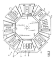
- is a front perspective view of a polygonal shaped electronic assembly in accordance with one embodiment of the invention, the assembly shown as including a cooling means centrally disposed therein in order to provide cooling of the several individual levels of substrates which form part of the assembly and which each include thereon heat generating electronic components;
- FIG. 2
- is a bottom perspective view of the assembly of FIG. 1, more clearly illustrating the plenum and fan assembly located within the plenum;
- FIG. 3
- is a top view of the polygonal shaped assembly of FIG. 1, further illustrating the various substrates (e.g., circuit cards) on the top level thereof and the components on each;
- FIG. 4
- is a side elevational view of the assembly of FIG. 1;
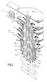
- FIG. 5
- is a partial view of the preferred cooling means of the invention as used within the assembly of FIG. 1, this cooling means shown as of a polygonal configuration but sectioned in half for illustration purposes;
- FIG. 6
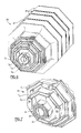
- is a perspective view of the bottom structure of the cooling means of FIG. 1;
- FIG. 7
- is an alternate embodiment of the bottom structure for the cooling means of the invention, this structure including as part thereof diffuser means to provide even, turbulent fluid flow in one of the duct members of the cooling means; and
- FIGS. 8 and 9
- represent alternate embodiments of the invention, the view in FIG. 8 being an annular (cylindrical) version while the view in FIG. 9 represents a rectangular version.
- In FIGS. 1-4, there is shown a multi-leveled electronic assembly 11 in accordance with a preferred embodiment of the invention. As indicated above, assembly 11 is preferably one for use in information handling systems (computers) and, even more particularly, for use in such systems currently referred to in the technology as supercomputers. As such, these assemblies generate extraordinarily large quantities of heat which must be effectively removed in order for proper operation of the assembly to occur. That is, the several heat generating electronic components used in assemblies such as supercomputers are known to generate large quantities of heat during operation due, primarily, to the passage of high electrical currents therethrough. While recent technology has resulted in the development of heat generating components (e.g., capacitors, power supplies, resistors, very large scale integrated (VLSI) modules) which satisfactorily operate at reduced heat levels in comparison to their predecessors, the design requirements of many of todays' supercomputers and similar information handling systems stipulate that these components be placed in close proximity within the system (e.g., to reduce line connection length, assure compactness of design, etc.). The overall result of such requirements is that heat levels in such systems has remained relatively high.
- As will be defined herein, the assembly 11 of the invention is able to provide positive cooling of electronic components located on various substrate levels within the invention in a simple but unique manner so that effective cooling of these components occurs. As will be defined, the cooling system of the invention is particularly adapted for the passage of air or other gaseous medium over the components being cooled, but this is not meant to limit the invention in that the cooling means of the invention is also readily capable of passing liquids or similar coolants (including flourocarbons) if desired.
- In FIGS. 1-4, electronic assembly 11 is shown to include a plurality of spacedly positioned
substrates 13. By the term substrate as used herein is meant to define an electrically insulative member having electrical wiring or similar circuitry therein and/or thereon and which is adaptable for having various electronic components (e.g., capacitors, modules, resistors) mounted thereon. Examples of such substrates include ceramic structures and known printed circuit board structures (e.g., those including a plurality of individual levels of circuit and power planes as part thereof). Such multilayered circuit boards and ceramic substrates are well known in the art and further description is not believed necessary. These substrates may be located on tray or similar supporting members e.g., tray 92 in FIG. 9, or, instead serve as the support structure itself and thus not include added supportive or the like structure thereunder. - As shown in FIGS. 1, 2 and 4, these
substrates 13 are located at various levels within assembly 11. With particular attention to FIG. 4., four levels "L" are clearly depicted in elevation. As more clearly shown in FIG. 4, these levels may not be equally spaced from each other in assembly 11 such that the respective coolant receiving "chambers" above each substrate need not all be the same size. For example, those in the illustrated second level (from the top of assembly 11) are clearly smaller in overall volume than those in the other three levels. - Each level "L" is shown to include a plurality of
individual substrates 13, each of which have a plurality of heat generating components positioned thereon. As better seen in FIG. 3, one level "L" (the top level only as shown in FIG. 3) includes a total of seven individual substrates, each havingside deflector walls 15 thereon. In the polygonal configuration of the invention as depicted in FIGS. 1-4, the number of sides is eight (assembly 11 thus being octagonal). However, this is not meant to limit the number of substrates, as indicated above wherein only seven such substrates may be used for this configuration. Thus, one or more substrates (e.g., 19) may in turn occupy more than one (substrate 19 in FIG. 3 occupying two) of the sides of assembly 11. This is considered an important feature of assembly 11 in that it results in a reduction of the total number of components required for the assembly. The remaining substrates shown in the top level of the assembly 11 in FIG. 3 may be to referred to as singular elements in that each occupies but one of the remaining sides of the assembly. - On each substrate is located a variety of heat generating electronic components which provide the necessary information handling functions for assembly 11. Such components may include capacitors 21 (FIG. 9), electronic modules 23 (typically including a heat sinking member as part thereof), resistors 25 (FIG. 9) and power supplies 29 (FIG. 9). Other electronic components, including pluggable printed
circuit cards 31 or the like (FIG. 9) may also be used in assembly 11. The number, type and location of these components as shown in the drawings as not meant to limit the invention. Various other combinations, spacings, etc. are readily possible. - As shown in the drawings, each substrate forms a platform or the like and includes the desired heat generating electronic components positioned thereon in the manner prescribed by the system designer. The relative close proximity of such components is best seen in FIG. 1. As is understood, this close relationship will result in the generation of substantial quantities of heat by these components during operation of the invention and there is thus an essential need to cool such components in order to assure satisfactory operation of assembly 11. Failure to do so, understandably, may result in eventual destruction or partial inoperation of these components.
- To provide this cooling, assembly 11 includes a cooling means 33 centrally located therein (surrounded by the individual substrates 13). Cooling means 33 comprises a plurality of individual cooling ducts D1, D2, D3 and D4, each of these ducts interconnecting a respective one of the aforedefined substrate levels with a means for generating the flow of fluid within assembly 11. Such a means, as illustrated in FIG. 2, preferably comprises an
electric fan 41 located within aplenum 43 which serves as a common housing for each of the individual duct members D1-D4. As is best shown in FIG. 5, each of the individual duct members of cooling means 33 includes alongitudinal chamber portion 45 which connects to a flaredend portion 47 of curved configuration so as to direct the upwardly forced fluid (e.g., air) onto the adjacent electronic components onsubstrates 13. Each longitudinal chamber portion is of polygonal configuration thus possessing the same number of sides as mentioned above for assembly 11. Thus, in the embodiment of FIG. 5, each longitudinal chamber of each duct member possesses an octagonal configuration such that the fluid is directed in a total of eight directions when passed up through the towered structure. Thus, the internal walls of each duct are substantially parallel to the sides (outer) of the respective portion of the assembly into which it directs the cooling fluid. - As also shown in FIG. 5, the individual duct members are oriented in a coaxial orientation about a common axis A-A (FIG. 5) centrally disposed in a vertical manner within assembly 11. These concentrically oriented duct members D1-D4 are thus spacedly positioned about the common axis A-A and each are adapted for receiving fluid in the lower end portions thereof adjacent the source (fan 41). Each duct member thus includes its own mass flow rate M (kg/m³), said flow rates indicated by the letters M1-M4 respectively in FIG. 5.
- The thermal analysis or design of this cooling system, like that of many cooling systems, requires a determination of the cooling flow requirements, system impedance (resistance) and component temperatures. The required fluid flow rate can be determined from the equation that the rate is equal to the total heat to be dissipated divided by the product of the fluid density, fluid specific heat and fluid temperature rise.
- The required flow rate to remove the power dissipation yields a desired temperature. This equation may be used to calculate the total volume of fluid required for the machine or individual components. In the instant situation, a calculation can be made for the flow rate required for each duct level. The total, M1, M2, M3, and M4, will equal the total for the entire machine. Hot spots on various components on different levels can be neutralized by baffles or similar members located at strategic locations on each level relative to the components having such hot spots.
- The fluid flowing through a machine encounters flow resistance which is proportional to the square of the velocity. This resistance (or impedance), and the fan, having its own impedance value, must be satisfactorily matched to each other in order to provide a proper operating point for the overall system.
- It is understood that the invention is not limited to only four individual levels "L" as depicted herein. That is, the cooling means as defined herein is readily capable of being used in electronic assemblies wherein other numbers of levels are utilized. It is preferred that one duct member be provided per level but this also is not meant to limit the invention in that more than one duct member may be used per individual level. This is represented in FIG. 5 wherein two duct members (D3 and D4) serve to direct fluid onto but a singular level (shown in phantom). This representation is for illustration purposes only in FIG. 5 to illustrate the possibility described. It is understood that the four leveled duct arrangement in FIG. 5 provides cooling fluid to four levels "L" in the embodiment of FIGS. 1-4.
- In one embodiment of the invention, a combined mass flow (m³/s) within the range of from about 0.024 m³/s (50 ft³/min) to about 450 ft ³/min is preferred when providing cooling fluid to a four tiered structure dissipating approximately 1000 to 5000 watts, such as depicted in FIGS. 1-4. Other flow rates are perfectly acceptable. As stated above, other numbers of levels may be used in the invention. Using a towered cooling structure as defined herein, the preferred number of duct members is within the range from about two to about ten when each duct member is designed for providing cooling fluid to a singular corresponding level. As indicated, however, other combinations are readily possible in accordance with the unique teachings of the invention, primarily when more than one duct members are used per individual level. The
preferred fan 41 for use of the invention may be obtained from the Torin Corporation, Torrington California, said fan generating approximately 37 W to 551 w (1/20 to 3/4 horsepower) and is operational using normal line sources. Other means for generating fluid flow are also readily possible in the instant invention, including pumps. Gravity flow (of liquids) is also possible. Theplenum 43 in whichfan 41 is located may be connected to any suitable air source, including external. Additionally, various filtering means may be used to provide appropriate air filtration, provided these assure minimum air velocities of 61 m (200 feet) per minute, such filtering means serving to prevent contaminants or similar undesirable elements from being directed onto the respective electronic components being cooled. Such filters are known and further description is not believed necessary. - As shown in FIG. 2,
fan 41 is located immediately adjacent the bottom end of the multileveled cooling means 33 so as to direct air directly into open ended ducts D1-D4. This open ended portion of cooling means 33 is better seen in FIG. 6. The octagonal configuration for each of the end sections of the respective longitudinal chamber portions for each duct member is also more clearly depicted in FIG. 6. Comparing FIGS. 5 and 6, it is also seen that the duct members include common, double side walls which serve to define the longitudinal chamber portions and which terminate at the approximate ends of the flared end portions of the cooling means. These double walled portions of the invention are closed at the extreme ends thereof, as shown in FIG. 5 (and partially in FIG. 6). The internal duct D4 and the outermost duct D1 are shown only to include a singular side wall as one of the walls thereof. It is understood, however, that these duct members may also include double sidewalls to thus assure added reinforcement and rigidity to the final structure. - In a preferred embodiment of the invention the towered, concentrically oriented duct members are each comprised of plastic (e.g., a thermoplastic). Other materials, including metallic (e.g., aluminum or steel), are also possible.
- In FIG. 7 there is shown a means for diffusing fluid as it passes through one of the duct members (e.g., D4) of cooling means 33. In FIG. 7, this diffusing means is shown as comprising an
apertured plate member 61 sealed over the end of duct D4 (and thus immediatelyadjacent fan 41, not shown) such that fluid directed toward duct D4 will be diffused by virtue of it passing through the several spaced apart apertures located within the plate. This creates a plenum resulting in the passage of turbulent flow of fluid through duct member D4 to thereby substantially remove laminar, peaked flow as might occur within this duct if a source such asfan 41 is used. Such peaked output is typical in fan-generated flow and is thus overcome by the invention so that uniform, even flow results in each of the individual flared end sections of the respective duct members. Although only one fluid diffuser is shown in FIG. 7, it is understood that other diffusers, including baffles and those similar to the apertured plate version in FIG. 7, may be used for the remaining duct members D1-D3. Thus, all duct members may include the diffuser on the end thereof to provide the advantages cited above. - A diffuser plate may also be located between the fan and the lower duct openings to create uniform flow to the ducts. The distance between the fan and plate should be at least the diameter of the fan blade to allow the rotating airstream to dissipate into static pressure. It is also understood that other configurations for such diffusers may be used, including, for example, various vane configurations or similar deflectors strategically positioned relative to the duct opening (between the fan and such opening). Such members may also serve to "tune" to amount of fluid flow to each duct (e.g., a
solid plate 93 located over a section of the respective duct opening, as in FIG. 7). - Although a polygonal (octagonal) configuration for the assembly 11 (and thus the internally positioned cooling means) is shown in FIGS. 1-7, it is understood that other configurations are readily possible. For example, in FIG. 8, there is shown an annular version of the invention wherein each of the individual levels having substrates thereon is shown to be of substantially annular configuration. Each level, as in the case of levels "L" in the above embodiment in FIG. 1, is parallel to the other levels in the assembly. Also shown in FIG. 8, the resulting flared end portions of each of the towered cooling structure is also annular, as is the corresponding longitudinal chamber portions for each duct member.
- In the embodiment of FIG. 9, a rectangular assembly is shown wherein a similarly configured, towered cooling structure is used. Thus, fluid is directed in four directions to four corresponding substrates adjacent each of the flared ends employed.
- In both of the embodiments of FIG. 8 and FIG. 9, a
plenum 43 having the desired air generator (fan) therein is preferably used although, as stated, other means are readily possible. - As shown in FIG. 9, two flared end portions of the towered cooling means are used for at least one (the upper) of the levels of substrates (as also illustrated representatively is FIG. 5). Thus, two ducts are used in the embodiment of FIG. 9 to thereby provide differential fluid flow to the heat generating electronic components on this upper level. By the term differential fluid flow is meant that, for example, greater flow rates may be utilized through one of the paired duct members per level (e.g., at the top) to provide greater cooling at different levels within each substrate level. This arrangement substantially eliminates the creation of "hot spots" as may occur in substrate configurations as a result of close positioning of the heat generating components thereon. This represents yet another significant feature of the invention as described herein.
- In FIGS. 1 and 3, there are shown (in phantom) wall members 81 (FIG. 1) and 83 (FIG. 3) which may be used to encase assembly 11 and, equally significant, to provide added means for fluid direction. In FIG. 1, for example, a wall 81 is shown as including a plurality of
openings 85 therein which will permit fluid passage directly through wall 81, if desired. It is also understood that walls similar to wall 81 may totally surround and thus enclose assembly 11 and thus may form part thereof. Only one such wall is illustrated in FIG. 1, however, for illustration purposes. In FIG. 3, threesuch walls 83 are shown to better illustrate this relationship. In FIG. 3,walls 83 may be solid in configuration and thus serve to direct fluid infringing thereon in another direction (e.g., downward). Such downward flow is facilitated by the provision of slots or the like 91 (FIG. 9) within the outermost periphery of the respective substrates and thus immediately adjacent such a wall so as to provide a channel along the outer periphery of assembly 11 through which fluid may be directed. Such a channel is also shown in phantom as being possible within at least one of the substrates shown in FIG. 3. It is understood that this fluid as directed by such walls as already passed over the respective heat generating electronic components. - Thus there has been shown and described a multileveled electronic assembly wherein a highly efficient cooling means is used to provide cooling for the heat generating electronic components used therein. The assembly as defined is capable of being adequately cooled using a cooling means of relatively simple yet effective construction, and thus one which is relatively inexpensive to manufacture. Such a means, as defined, is particularly useful for directing air or similar gaseous medium to the various components being cooled, but may also be utilized to direct liquids (e.g., flourocarbons) therethrough.
Claims (14)
- A multileveled electronic assembly (11) including a plurality of spacedly positioned substrates (13, 19) located at different levels (L) within said assembly and each including thereon a plurality of heat generating electronic components (21, 23, 25, 29), said assembly including means to provide cooling of said electronic components, said cooling means (33) comprises a plurality of individual duct members (D) oriented within said assembly, each of said duct members directing cooling fluid onto said electronic components on a respective one of said substrates to cool said electronic components.
- The assembly according to Claim 1 wherein said plurality of duct members of said cooling means are coaxially oriented.
- The assembly according to Claim 2 wherein said cooling means is substantially centrally disposed within said electronic assembly, said levels of said substrates substantially surrounding said cooling means.
- The assembly according to any one of the preceding Claims wherein each of said duct members comprises a longitudinal chamber portion (45) and a flared end portion (47), each of said flared end portions being located within said assembly adjacent each of said respective substrates having said electronic components thereon.
- The assembly according to Claim 4 wherein each of said flared end portions of said cooling means is substantially annular in shape.
- The assembly according to Claim 4 wherein each of said flared end portions of said cooling means is of polygonal shape to thereby direct cooling fluid passing through said duct means in a plurality of directions.
- The assembly according to Claim 6 wherein the shape of each of said flare portions of said cooling means is rectangular, the number of directions said fluid is directed being four.
- The assembly according to Claim 6 wherein the shape of each of said flare portions of said cooling means is octagonal, the number of directions said fluid is directed being eight.
- The assembly according to Claim 1 wherein the number of said duct members directing fluid onto at least one of said levels of said substrates is at least two, said two duct members directing fluid to said one level thereby providing differential fluid flow across said electronic components located on said substrates on said one level.
- The assembly according to any one of the preceding Claims wherein each of said duct members is joined to a common plenum member (43), said plenum including means (41) for generating flow of said fluid therein, preferably a fan.
- The assembly according to Claim 10 further including means for diffusing said fluid generated by said generating means prior to said fluid entering at least one of said duct members to thereby provide turbulent, even flow of said fluid to said duct member receiving said fluid.
- The assembly according to Claim 11 wherein said means for diffusing said fluid comprises an apertured plate member (66) located substantially across said duct member, said plate member including a plurality of spacedly oriented apertures therein.
- The assembly according to any one of the preceding Claims further including wall members (81) located adjacent each of said levels of substrates along the outer periphery thereof to assist in directing said fluid directed over said electronic components after said fluid has passed over said components.
- The assembly according to Claim 13 wherein each of said walls includes a plurality of openings therein for having said fluid passing over said components pass therethrough.
Applications Claiming Priority (2)
| Application Number | Priority Date | Filing Date | Title |
|---|---|---|---|
| US495863 | 1990-03-19 | ||
| US07/495,863 US5063475A (en) | 1990-03-19 | 1990-03-19 | Multileveled electronic assembly with cooling means |
Publications (3)
| Publication Number | Publication Date |
|---|---|
| EP0447819A2 true EP0447819A2 (en) | 1991-09-25 |
| EP0447819A3 EP0447819A3 (en) | 1991-12-11 |
| EP0447819B1 EP0447819B1 (en) | 1995-01-25 |
Family
ID=23970290
Family Applications (1)
| Application Number | Title | Priority Date | Filing Date |
|---|---|---|---|
| EP91102392A Expired - Lifetime EP0447819B1 (en) | 1990-03-19 | 1991-02-20 | Multileveled electronic assembly with cooling means |
Country Status (4)
| Country | Link |
|---|---|
| US (1) | US5063475A (en) |
| EP (1) | EP0447819B1 (en) |
| JP (1) | JPH088424B2 (en) |
| DE (1) | DE69106909T2 (en) |
Cited By (6)
| Publication number | Priority date | Publication date | Assignee | Title |
|---|---|---|---|---|
| WO1994017649A1 (en) * | 1993-01-20 | 1994-08-04 | Wavedriver Limited | Mounting assembly for power semiconductors |
| WO2005031549A2 (en) * | 2003-09-29 | 2005-04-07 | Universität Zürich | Parallel data processing device |
| WO2013156742A1 (en) * | 2012-04-20 | 2013-10-24 | No Rack | Rack for computer servers |
| CN104125729A (en) * | 2014-08-11 | 2014-10-29 | 国家电网公司 | Enclosed type cabinet for use in machine room |
| WO2017156726A1 (en) * | 2016-03-16 | 2017-09-21 | 厦门特欧普材料科技有限公司 | Safe cylindrical combined cabinet for outdoor use |
| CN115015577A (en) * | 2022-07-04 | 2022-09-06 | 武汉新烽光电股份有限公司 | Double-beam laser Doppler velocimeter |
Families Citing this family (56)
| Publication number | Priority date | Publication date | Assignee | Title |
|---|---|---|---|---|
| US5260850A (en) * | 1991-03-08 | 1993-11-09 | Cray Computer Corporation | Logic module assembly for confining and directing the flow of cooling fluid |
| US5150279A (en) * | 1991-03-18 | 1992-09-22 | International Business Machines Corporation | High performance computer system with platters and unidirectional storage modules therebetween |
| EP0506224A3 (en) * | 1991-03-26 | 1994-05-11 | Ibm | Computer system package |
| WO1992019013A1 (en) * | 1991-04-16 | 1992-10-29 | Arthur Iversen | Power semiconductor packaging |
| USRE35807E (en) * | 1991-04-16 | 1998-05-26 | Iversen Arthur H | Power semiconductor packaging |
| US5278495A (en) * | 1991-11-08 | 1994-01-11 | Ncr Corporation | Memory and apparatus for a thermally accelerated reliability testing |
| US5339214A (en) * | 1993-02-12 | 1994-08-16 | Intel Corporation | Multiple-fan microprocessor cooling through a finned heat pipe |
| US5289694A (en) * | 1993-02-26 | 1994-03-01 | At&T Bell Laboratories | Circuit card mounting assembly |
| US5471850A (en) * | 1993-07-09 | 1995-12-05 | Acurex Corporation | Refrigeration system and method for very large scale integrated circuits |
| US5497288A (en) * | 1994-08-31 | 1996-03-05 | International Business Machines Corporation | Apparatus for tilted serial cooling in an electronic system |
| FR2728116A1 (en) * | 1994-12-12 | 1996-06-14 | Valeo Thermique Habitacle | POWER REGULATOR EQUIPMENT FOR ELECTRIC MOTOR AND CENTRIFUGAL FAN EQUIPPED WITH SUCH EQUIPMENT |
| US5513070A (en) * | 1994-12-16 | 1996-04-30 | Intel Corporation | Dissipation of heat through keyboard using a heat pipe |
| US5784255A (en) * | 1995-12-04 | 1998-07-21 | Integrated Device Technology, Inc. | Device and method for convective cooling of an electronic component |
| US5909357A (en) * | 1997-04-24 | 1999-06-01 | Orr; Tom | Vertically stacked computer modules shaped to indicate compatibility with vertical cooling shaft extending throughout |
| US5953930A (en) * | 1998-03-31 | 1999-09-21 | International Business Machines Corporation | Evaporator for use in an extended air cooling system for electronic components |
| US6223810B1 (en) | 1998-03-31 | 2001-05-01 | International Business Machines | Extended air cooling with heat loop for dense or compact configurations of electronic components |
| US6657121B2 (en) * | 2001-06-27 | 2003-12-02 | Thermal Corp. | Thermal management system and method for electronics system |
| US6536510B2 (en) | 2001-07-10 | 2003-03-25 | Thermal Corp. | Thermal bus for cabinets housing high power electronics equipment |
| US6388882B1 (en) | 2001-07-19 | 2002-05-14 | Thermal Corp. | Integrated thermal architecture for thermal management of high power electronics |
| US6856037B2 (en) * | 2001-11-26 | 2005-02-15 | Sony Corporation | Method and apparatus for converting dissipated heat to work energy |
| TW592029B (en) * | 2003-04-11 | 2004-06-11 | Delta Electronics Inc | Electronic apparatus with natural convection structure |
| JP2005019562A (en) * | 2003-06-24 | 2005-01-20 | Hitachi Ltd | Cooling structure of electronic apparatus |
| TW200741470A (en) * | 2006-04-19 | 2007-11-01 | Tyan Computer Corp | Multi-processor system and tubelike computer architecture thereof |
| DE102006018709B3 (en) * | 2006-04-20 | 2007-10-11 | Nft Nanofiltertechnik Gmbh | Heat exchanger for cooling electronic component, has two stages arranged consecutively, where each stage has heat exchanging channel and guiding channels that are in flow connection with heat exchanging channels of next stages |
| US7918799B2 (en) * | 2008-02-18 | 2011-04-05 | General Electric Company | Method and interface for cooling electronics that generate heat |
| FR2929482B1 (en) * | 2008-04-01 | 2013-07-05 | Thales Sa | COMPUTER WITH SIMPLIFIED ARRANGEMENT, FOR AERONAUTICS |
| US8773864B2 (en) * | 2008-06-18 | 2014-07-08 | Lockheed Martin Corporation | Enclosure assembly housing at least one electronic board assembly and systems using same |
| US8189345B2 (en) * | 2008-06-18 | 2012-05-29 | Lockheed Martin Corporation | Electronics module, enclosure assembly housing same, and related systems and methods |
| CN201229538Y (en) * | 2008-07-04 | 2009-04-29 | 鸿富锦精密工业(深圳)有限公司 | Computer machine box |
| US8659901B2 (en) * | 2010-02-04 | 2014-02-25 | P-Wave-Holdings, LLC | Active antenna array heatsink |
| US8279597B2 (en) | 2010-05-27 | 2012-10-02 | International Business Machines Corporation | Heatsink allowing in-situ maintenance in a stackable module |
| US8174826B2 (en) | 2010-05-27 | 2012-05-08 | International Business Machines Corporation | Liquid cooling system for stackable modules in energy-efficient computing systems |
| US8179674B2 (en) * | 2010-05-28 | 2012-05-15 | International Business Machines Corporation | Scalable space-optimized and energy-efficient computing system |
| US8358503B2 (en) | 2010-05-28 | 2013-01-22 | International Business Machines Corporation | Stackable module for energy-efficient computing systems |
| US10209003B2 (en) | 2012-02-21 | 2019-02-19 | Thermal Corp. | Electronics cabinet and rack cooling system and method |
| US9521766B2 (en) * | 2012-06-27 | 2016-12-13 | CommScope Connectivity Belgium BVBA | High density telecommunications systems with cable management and heat dissipation features |
| US8842432B2 (en) * | 2012-09-22 | 2014-09-23 | Facebook, Inc. | Arrangement of computing assets in a data center |
| JP6070331B2 (en) * | 2013-03-25 | 2017-02-01 | 日本電気株式会社 | rack |
| TWI539894B (en) * | 2014-11-28 | 2016-06-21 | 財團法人工業技術研究院 | Power module |
| US9532488B2 (en) | 2015-03-09 | 2016-12-27 | Vapor IO Inc. | Rack for computing equipment |
| US10833940B2 (en) | 2015-03-09 | 2020-11-10 | Vapor IO Inc. | Autonomous distributed workload and infrastructure scheduling |
| US10404523B2 (en) | 2015-03-09 | 2019-09-03 | Vapor IO Inc. | Data center management with rack-controllers |
| US10257268B2 (en) | 2015-03-09 | 2019-04-09 | Vapor IO Inc. | Distributed peer-to-peer data center management |
| US10039211B2 (en) | 2015-03-09 | 2018-07-31 | Vapor IO Inc. | Rack for computing equipment |
| TWM520229U (en) * | 2015-07-16 | 2016-04-11 | 鋐寶科技股份有限公司 | Electronic apparatus |
| US10454772B2 (en) | 2015-10-30 | 2019-10-22 | Vapor IO Inc. | Compact uninteruptable power supply |
| US9985842B2 (en) | 2015-10-30 | 2018-05-29 | Vapor IO Inc. | Bus bar power adapter for AC-input, hot-swap power supplies |
| CN105592644A (en) * | 2016-03-16 | 2016-05-18 | 厦门特欧普材料科技有限公司 | Outdoor safety cylindrical composite cabinet |
| JP6644907B2 (en) | 2016-11-12 | 2020-02-12 | 株式会社ExaScaler | Electronic equipment for immersion cooling, power supply unit, and cooling system |
| FR3074011B1 (en) * | 2017-11-21 | 2019-12-20 | Safran Electronics & Defense | ELECTRIC POWER MODULE |
| US10853460B2 (en) * | 2017-12-04 | 2020-12-01 | Vapor IO Inc. | Modular data center |
| US10499524B2 (en) | 2017-12-20 | 2019-12-03 | Capital One Services, Llc | Apparatus for mounting a processor for cluster computing |
| US10334760B1 (en) * | 2018-01-12 | 2019-06-25 | Jed A. Darland | System and method for helical cooling tower for efficient cooling |
| US10746084B2 (en) * | 2018-12-13 | 2020-08-18 | General Electric Company | Liquid driven thermal module and thermal management system |
| US11071221B2 (en) * | 2018-12-26 | 2021-07-20 | General Dynamics Mission Systems, Inc. | Multi-card subsystem for embedded computing systems |
| TWI714037B (en) * | 2019-03-26 | 2020-12-21 | 緯創資通股份有限公司 | Air flow generating system for liquid tank, immersion cooling apparatus having the same, and method for operating the same |
Citations (5)
| Publication number | Priority date | Publication date | Assignee | Title |
|---|---|---|---|---|
| FR1571823A (en) * | 1967-07-28 | 1969-06-20 | ||
| JPS5720458A (en) * | 1980-07-10 | 1982-02-02 | Nec Corp | Cooling system for package of electronic circuit |
| JPS5796557A (en) * | 1980-12-08 | 1982-06-15 | Toshiba Corp | Cooling supporting base for semiconductor substrate |
| DE8420362U1 (en) * | 1984-07-06 | 1984-11-15 | Siemens AG, 1000 Berlin und 8000 München | Ventilation arrangement with an air guiding device |
| WO1988000429A1 (en) * | 1986-07-03 | 1988-01-14 | Unisys Corporation | Parallel-flow air system for cooling electronic equipment |
Family Cites Families (9)
| Publication number | Priority date | Publication date | Assignee | Title |
|---|---|---|---|---|
| US3434014A (en) * | 1967-06-13 | 1969-03-18 | Rca Corp | Packaging of electrical equipment |
| US4417295A (en) * | 1977-06-30 | 1983-11-22 | International Business Machines Corporation | Air jet powered cooling system for electronic assemblies |
| US4335781A (en) * | 1978-10-02 | 1982-06-22 | Motorola Inc. | High power cooler and method thereof |
| DE3028340A1 (en) * | 1980-07-25 | 1982-02-25 | Fa. Dr. Willmar Schwabe, 7500 Karlsruhe | AMINO-DESOXY-1.4; 3.6-DIANHYDRO-HEXIT-NITRATE |
| US4590538A (en) * | 1982-11-18 | 1986-05-20 | Cray Research, Inc. | Immersion cooled high density electronic assembly |
| US4502100A (en) * | 1982-11-24 | 1985-02-26 | International Business Machines Corporation | Cooling system with counter flow of coolant |
| US4633371A (en) * | 1984-09-17 | 1986-12-30 | Amdahl Corporation | Heat pipe heat exchanger for large scale integrated circuits |
| US4733293A (en) * | 1987-02-13 | 1988-03-22 | Unisys Corporation | Heat sink device assembly for encumbered IC package |
| US4894749A (en) * | 1987-08-31 | 1990-01-16 | AT&T Information Systems Inc American Telephone and Telegraph Company | Option slot filler board |
-
1990
- 1990-03-19 US US07/495,863 patent/US5063475A/en not_active Expired - Lifetime
-
1991
- 1991-02-20 EP EP91102392A patent/EP0447819B1/en not_active Expired - Lifetime
- 1991-02-20 DE DE69106909T patent/DE69106909T2/en not_active Expired - Fee Related
- 1991-03-04 JP JP3061037A patent/JPH088424B2/en not_active Expired - Fee Related
Patent Citations (5)
| Publication number | Priority date | Publication date | Assignee | Title |
|---|---|---|---|---|
| FR1571823A (en) * | 1967-07-28 | 1969-06-20 | ||
| JPS5720458A (en) * | 1980-07-10 | 1982-02-02 | Nec Corp | Cooling system for package of electronic circuit |
| JPS5796557A (en) * | 1980-12-08 | 1982-06-15 | Toshiba Corp | Cooling supporting base for semiconductor substrate |
| DE8420362U1 (en) * | 1984-07-06 | 1984-11-15 | Siemens AG, 1000 Berlin und 8000 München | Ventilation arrangement with an air guiding device |
| WO1988000429A1 (en) * | 1986-07-03 | 1988-01-14 | Unisys Corporation | Parallel-flow air system for cooling electronic equipment |
Non-Patent Citations (3)
| Title |
|---|
| IBM TECHNICAL DISCLOSURE BULLETIN. vol. 30, no. 9, February 1988, NEW YORK US pages 428 - 429; "Compact stacked memory package" * |
| PATENT ABSTRACTS OF JAPAN vol. 6, no. 182 (E-131)(1060) 18 September 1982, & JP-A-57 096557 (TOKYO SHIBAURA DENKI) 15 June 1982, * |
| PATENT ABSTRACTS OF JAPAN vol. 6, no. 87 (E-108)(965) 25 May 1982, & JP-A-57 020458 (NIPPON DENKI) 02 February 1982, * |
Cited By (10)
| Publication number | Priority date | Publication date | Assignee | Title |
|---|---|---|---|---|
| WO1994017649A1 (en) * | 1993-01-20 | 1994-08-04 | Wavedriver Limited | Mounting assembly for power semiconductors |
| AU696858B2 (en) * | 1993-01-20 | 1998-09-17 | Wavedriver Limited | Mounting assembly for power semiconductors |
| WO2005031549A2 (en) * | 2003-09-29 | 2005-04-07 | Universität Zürich | Parallel data processing device |
| WO2005031549A3 (en) * | 2003-09-29 | 2005-07-21 | Univ Zuerich | Parallel data processing device |
| WO2013156742A1 (en) * | 2012-04-20 | 2013-10-24 | No Rack | Rack for computer servers |
| FR2989861A1 (en) * | 2012-04-20 | 2013-10-25 | No Rack | BAY OF COMPUTER SERVERS |
| CN104125729A (en) * | 2014-08-11 | 2014-10-29 | 国家电网公司 | Enclosed type cabinet for use in machine room |
| WO2017156726A1 (en) * | 2016-03-16 | 2017-09-21 | 厦门特欧普材料科技有限公司 | Safe cylindrical combined cabinet for outdoor use |
| GB2564039A (en) * | 2016-03-16 | 2019-01-02 | Xiamen Toppla Mat Tech Co Ltd | Safe cylindrical combined cabinet for outdoor use |
| CN115015577A (en) * | 2022-07-04 | 2022-09-06 | 武汉新烽光电股份有限公司 | Double-beam laser Doppler velocimeter |
Also Published As
| Publication number | Publication date |
|---|---|
| JPH04221898A (en) | 1992-08-12 |
| US5063475A (en) | 1991-11-05 |
| EP0447819A3 (en) | 1991-12-11 |
| DE69106909D1 (en) | 1995-03-09 |
| EP0447819B1 (en) | 1995-01-25 |
| JPH088424B2 (en) | 1996-01-29 |
| DE69106909T2 (en) | 1995-08-10 |
Similar Documents
| Publication | Publication Date | Title |
|---|---|---|
| EP0447819B1 (en) | Multileveled electronic assembly with cooling means | |
| US5440450A (en) | Housing cooling system | |
| US6813149B2 (en) | High capacity air-cooling systems for electronic apparatus and associated methods | |
| US6525936B2 (en) | Air jet cooling arrangement for electronic systems | |
| US5063476A (en) | Apparatus for controlled air-impingement module cooling | |
| EP0427656B1 (en) | Improved apparatus for cooling electronics components | |
| US5828549A (en) | Combination heat sink and air duct for cooling processors with a series air flow | |
| US6778390B2 (en) | High-performance heat sink for printed circuit boards | |
| US7382616B2 (en) | Cooling system for computer hardware | |
| US5923531A (en) | Enhanced circuit board arrangement for a computer | |
| US5860291A (en) | Chambered forced cooling method | |
| US6288895B1 (en) | Apparatus for cooling electronic components within a computer system enclosure | |
| US7002799B2 (en) | External liquid loop heat exchanger for an electronic system | |
| US7848101B2 (en) | System and method for cooling electronic systems | |
| EP1133906B1 (en) | Parallel cooling of high power devices in a serially cooled environment | |
| US7120019B2 (en) | Coaxial air ducts and fans for cooling and electronic component | |
| US5297005A (en) | Apparatus and method for cooling heat generating electronic components in a cabinet | |
| US6459576B1 (en) | Fan based heat exchanger | |
| WO2002104090A1 (en) | Failure-tolerant high-density card rack cooling system and method | |
| US6504714B1 (en) | Multi-level thermal management system and method | |
| US20140326436A1 (en) | Carrier with adjustable heat removal elements | |
| US6011688A (en) | Compact apparatus for cooling a plurality of circuit packs arranged with a cage | |
| US5873407A (en) | Windblown-type heat-dissipating device for computer mother board | |
| EP1971196B1 (en) | Clamshell enclosure for electronic circuit assemblies | |
| SU736390A1 (en) | Device for cooling radio electronic apparatus |
Legal Events
| Date | Code | Title | Description |
|---|---|---|---|
| PUAI | Public reference made under article 153(3) epc to a published international application that has entered the european phase |
Free format text: ORIGINAL CODE: 0009012 |
|
| AK | Designated contracting states |
Kind code of ref document: A2 Designated state(s): DE FR GB |
|
| PUAL | Search report despatched |
Free format text: ORIGINAL CODE: 0009013 |
|
| AK | Designated contracting states |
Kind code of ref document: A3 Designated state(s): DE FR GB |
|
| 17P | Request for examination filed |
Effective date: 19911219 |
|
| 17Q | First examination report despatched |
Effective date: 19931004 |
|
| GRAA | (expected) grant |
Free format text: ORIGINAL CODE: 0009210 |
|
| AK | Designated contracting states |
Kind code of ref document: B1 Designated state(s): DE FR GB |
|
| PGFP | Annual fee paid to national office [announced via postgrant information from national office to epo] |
Ref country code: FR Payment date: 19950128 Year of fee payment: 5 |
|
| PGFP | Annual fee paid to national office [announced via postgrant information from national office to epo] |
Ref country code: DE Payment date: 19950223 Year of fee payment: 5 |
|
| REF | Corresponds to: |
Ref document number: 69106909 Country of ref document: DE Date of ref document: 19950309 |
|
| ET | Fr: translation filed | ||
| PLBE | No opposition filed within time limit |
Free format text: ORIGINAL CODE: 0009261 |
|
| STAA | Information on the status of an ep patent application or granted ep patent |
Free format text: STATUS: NO OPPOSITION FILED WITHIN TIME LIMIT |
|
| 26N | No opposition filed | ||
| PG25 | Lapsed in a contracting state [announced via postgrant information from national office to epo] |
Ref country code: FR Effective date: 19961031 |
|
| PG25 | Lapsed in a contracting state [announced via postgrant information from national office to epo] |
Ref country code: DE Effective date: 19961101 |
|
| REG | Reference to a national code |
Ref country code: FR Ref legal event code: ST |
|
| REG | Reference to a national code |
Ref country code: GB Ref legal event code: IF02 |
|
| PGFP | Annual fee paid to national office [announced via postgrant information from national office to epo] |
Ref country code: GB Payment date: 20020204 Year of fee payment: 12 |
|
| PG25 | Lapsed in a contracting state [announced via postgrant information from national office to epo] |
Ref country code: GB Free format text: LAPSE BECAUSE OF NON-PAYMENT OF DUE FEES Effective date: 20030220 |
|
| GBPC | Gb: european patent ceased through non-payment of renewal fee |