EP0447810B1 - Measuring device for filling level or other mechanical properties of electrically conductive liquid - Google Patents
Measuring device for filling level or other mechanical properties of electrically conductive liquid Download PDFInfo
- Publication number
- EP0447810B1 EP0447810B1 EP91102305A EP91102305A EP0447810B1 EP 0447810 B1 EP0447810 B1 EP 0447810B1 EP 91102305 A EP91102305 A EP 91102305A EP 91102305 A EP91102305 A EP 91102305A EP 0447810 B1 EP0447810 B1 EP 0447810B1
- Authority
- EP
- European Patent Office
- Prior art keywords
- measuring
- container
- liquid
- arrangement according
- measuring arrangement
- Prior art date
- Legal status (The legal status is an assumption and is not a legal conclusion. Google has not performed a legal analysis and makes no representation as to the accuracy of the status listed.)
- Expired - Lifetime
Links
- 239000007788 liquid Substances 0.000 title claims abstract description 92
- 238000005259 measurement Methods 0.000 claims abstract description 35
- 238000011156 evaluation Methods 0.000 claims abstract description 26
- 239000000758 substrate Substances 0.000 claims description 7
- 238000013016 damping Methods 0.000 claims description 3
- 238000005192 partition Methods 0.000 claims description 3
- 230000001960 triggered effect Effects 0.000 claims description 3
- 230000005484 gravity Effects 0.000 claims 1
- 238000000034 method Methods 0.000 claims 1
- 230000001133 acceleration Effects 0.000 abstract description 4
- 238000005516 engineering process Methods 0.000 description 13
- 238000013461 design Methods 0.000 description 3
- 230000001070 adhesive effect Effects 0.000 description 2
- 238000010276 construction Methods 0.000 description 2
- 238000001514 detection method Methods 0.000 description 2
- 230000000694 effects Effects 0.000 description 2
- 238000004519 manufacturing process Methods 0.000 description 2
- 230000035945 sensitivity Effects 0.000 description 2
- XLYOFNOQVPJJNP-UHFFFAOYSA-N water Substances O XLYOFNOQVPJJNP-UHFFFAOYSA-N 0.000 description 2
- 241000238633 Odonata Species 0.000 description 1
- 239000000853 adhesive Substances 0.000 description 1
- 238000005452 bending Methods 0.000 description 1
- 239000011248 coating agent Substances 0.000 description 1
- 238000000576 coating method Methods 0.000 description 1
- 238000012937 correction Methods 0.000 description 1
- 238000010586 diagram Methods 0.000 description 1
- 238000006073 displacement reaction Methods 0.000 description 1
- 239000003792 electrolyte Substances 0.000 description 1
- 238000012854 evaluation process Methods 0.000 description 1
- 230000002349 favourable effect Effects 0.000 description 1
- 239000000463 material Substances 0.000 description 1
- 230000003287 optical effect Effects 0.000 description 1
- 230000010287 polarization Effects 0.000 description 1
- 238000012360 testing method Methods 0.000 description 1
- 239000010409 thin film Substances 0.000 description 1
Images


Classifications
-
- G—PHYSICS
- G01—MEASURING; TESTING
- G01P—MEASURING LINEAR OR ANGULAR SPEED, ACCELERATION, DECELERATION, OR SHOCK; INDICATING PRESENCE, ABSENCE, OR DIRECTION, OF MOVEMENT
- G01P15/00—Measuring acceleration; Measuring deceleration; Measuring shock, i.e. sudden change of acceleration
- G01P15/02—Measuring acceleration; Measuring deceleration; Measuring shock, i.e. sudden change of acceleration by making use of inertia forces using solid seismic masses
- G01P15/08—Measuring acceleration; Measuring deceleration; Measuring shock, i.e. sudden change of acceleration by making use of inertia forces using solid seismic masses with conversion into electric or magnetic values
- G01P15/12—Measuring acceleration; Measuring deceleration; Measuring shock, i.e. sudden change of acceleration by making use of inertia forces using solid seismic masses with conversion into electric or magnetic values by alteration of electrical resistance
-
- G—PHYSICS
- G01—MEASURING; TESTING
- G01C—MEASURING DISTANCES, LEVELS OR BEARINGS; SURVEYING; NAVIGATION; GYROSCOPIC INSTRUMENTS; PHOTOGRAMMETRY OR VIDEOGRAMMETRY
- G01C9/00—Measuring inclination, e.g. by clinometers, by levels
- G01C9/02—Details
- G01C9/06—Electric or photoelectric indication or reading means
-
- G—PHYSICS
- G01—MEASURING; TESTING
- G01C—MEASURING DISTANCES, LEVELS OR BEARINGS; SURVEYING; NAVIGATION; GYROSCOPIC INSTRUMENTS; PHOTOGRAMMETRY OR VIDEOGRAMMETRY
- G01C9/00—Measuring inclination, e.g. by clinometers, by levels
- G01C9/18—Measuring inclination, e.g. by clinometers, by levels by using liquids
- G01C9/20—Measuring inclination, e.g. by clinometers, by levels by using liquids the indication being based on the inclination of the surface of a liquid relative to its container
-
- G—PHYSICS
- G01—MEASURING; TESTING
- G01F—MEASURING VOLUME, VOLUME FLOW, MASS FLOW OR LIQUID LEVEL; METERING BY VOLUME
- G01F23/00—Indicating or measuring liquid level or level of fluent solid material, e.g. indicating in terms of volume or indicating by means of an alarm
- G01F23/22—Indicating or measuring liquid level or level of fluent solid material, e.g. indicating in terms of volume or indicating by means of an alarm by measuring physical variables, other than linear dimensions, pressure or weight, dependent on the level to be measured, e.g. by difference of heat transfer of steam or water
-
- G—PHYSICS
- G01—MEASURING; TESTING
- G01P—MEASURING LINEAR OR ANGULAR SPEED, ACCELERATION, DECELERATION, OR SHOCK; INDICATING PRESENCE, ABSENCE, OR DIRECTION, OF MOVEMENT
- G01P15/00—Measuring acceleration; Measuring deceleration; Measuring shock, i.e. sudden change of acceleration
- G01P15/006—Measuring acceleration; Measuring deceleration; Measuring shock, i.e. sudden change of acceleration by making use of fluid seismic masses
-
- G—PHYSICS
- G01—MEASURING; TESTING
- G01P—MEASURING LINEAR OR ANGULAR SPEED, ACCELERATION, DECELERATION, OR SHOCK; INDICATING PRESENCE, ABSENCE, OR DIRECTION, OF MOVEMENT
- G01P15/00—Measuring acceleration; Measuring deceleration; Measuring shock, i.e. sudden change of acceleration
- G01P15/02—Measuring acceleration; Measuring deceleration; Measuring shock, i.e. sudden change of acceleration by making use of inertia forces using solid seismic masses
- G01P15/08—Measuring acceleration; Measuring deceleration; Measuring shock, i.e. sudden change of acceleration by making use of inertia forces using solid seismic masses with conversion into electric or magnetic values
- G01P15/0888—Measuring acceleration; Measuring deceleration; Measuring shock, i.e. sudden change of acceleration by making use of inertia forces using solid seismic masses with conversion into electric or magnetic values for indicating angular acceleration
-
- G—PHYSICS
- G01—MEASURING; TESTING
- G01P—MEASURING LINEAR OR ANGULAR SPEED, ACCELERATION, DECELERATION, OR SHOCK; INDICATING PRESENCE, ABSENCE, OR DIRECTION, OF MOVEMENT
- G01P3/00—Measuring linear or angular speed; Measuring differences of linear or angular speeds
- G01P3/26—Devices characterised by the use of fluids
- G01P3/30—Devices characterised by the use of fluids by using centrifugal forces of fluids
-
- G—PHYSICS
- G01—MEASURING; TESTING
- G01P—MEASURING LINEAR OR ANGULAR SPEED, ACCELERATION, DECELERATION, OR SHOCK; INDICATING PRESENCE, ABSENCE, OR DIRECTION, OF MOVEMENT
- G01P3/00—Measuring linear or angular speed; Measuring differences of linear or angular speeds
- G01P3/42—Devices characterised by the use of electric or magnetic means
- G01P3/44—Devices characterised by the use of electric or magnetic means for measuring angular speed
Definitions
- the invention relates to an electrical measuring arrangement for the conductometric measurement of the fill level or mechanical data derived therefrom of an electrically conductive liquid which is in a preferably closed container and has fixed electrical properties, with the features of the preamble of claim 1.
- an electrically conductive liquid which is in a preferably closed container and has fixed electrical properties, with the features of the preamble of claim 1.
- the invention relates to an electrical measuring arrangement for the conductometric measurement of the fill level, and is therefore different from electrical measuring arrangements for the capacitive measurement of the fill level. Not only the level directly, but also mechanical data of the liquid derived therefrom, in particular thus the inclination of the liquid level, can be the goal of the measurement with the claimed electrical measuring arrangement.
- the concept of the fill level of a liquid in a container also makes it clear that it must be a liquid with an essentially flat liquid level, the fill level of which can actually be measured as such in the container.
- the starting point for the teaching of the invention is an electrical measuring arrangement for the conductometric measurement of the fill level of an electrolyte liquid located in a container, which wets sensor electrodes in the container (DE - A - 34 11 252).
- the fill level in the container open up here is determined and from this the inclination of the vehicle in which this container is arranged is determined. It is essential that a liquid level is formed at all on this liquid in the container, that is to say the container is only partially filled with the liquid, so that a full-surface free space remains above the liquid. Even if the container in this prior art is shown open at the top, the container at the top will often also be closed to avoid loss of liquid.
- two measuring sensors are implemented, each of which has two measuring electrodes lying at a certain lateral distance from one another and wetted with the liquid.
- the electrodes are designed as stick electrodes or plate electrodes and plunge vertically into the liquid from above, over a length that is at least equal to the maximum height difference of the liquid level at the location of the respective measuring electrode.
- the value of the inclination of the liquid level can be determined directly and continuously from the measured ratio of the resistances.
- the container can be tilted about a tilting axis which is in any case virtually in the center on the bottom of the container, the measuring sensors being effective on both sides of the tilting axis which is in any case virtually in the center.
- the tilt axis does not have to be physically in the middle, the container can finally tilt about a distant tilt axis.
- the tilting axis is virtually always present in the center of the bottom of the container, because each tilting can ultimately be broken down into a tilting movement around the tilting axis virtually present in the center of the bottom and a displacement of the container parallel to itself.
- the measuring arrangement explained above is structurally relatively complex with its rod or plate electrodes and mechanically relatively sensitive.
- an electrical measuring arrangement for conductometric measurement in an electrically conductive liquid located in a container in which the conductometric measurement with two measuring sensors arranged on the bottom of the container, each with two in a particular one lateral spacing from each other, with the liquid contacting measuring electrodes. These measuring electrodes are arranged flat on the bottom of the container and each form a stray field in the liquid.
- This known electrical measuring arrangement is used exclusively for inclination measurement.
- the container is shaped in a certain way, namely curved in the manner of a dragonfly. This is necessary so that an air bubble in the liquid is always defined on the ceiling of the container opposite the floor and the measuring electrodes arranged there.
- the level of the liquid in the container is not measured here.
- Such a fill level is not defined here at all, since the air bubble only defines an inner surface, but not a regular liquid level of the liquid in the container.
- This is also logical, as the air bubble is supposed to change its position on the curved ceiling of the container depending on the inclination of the container to the left and right.
- the stray field extends over two measuring electrodes in the liquid to the ceiling of the container when the air bubble has moved from this area into the area of the other measuring electrodes. The constriction of the field lines of the stray field by the air bubble entering the stray field and displacing the liquid there changes the current flow through the measuring electrodes and thus the ultimately externally measured conductance.
- the measuring accuracy of an electrical measuring arrangement with a level as shown and described in GB-A-993,715 is primarily defined by the shape of the necessarily curved container.
- the measuring accuracy of the electrical measuring arrangement known from this document for the conductometric measurement of an inclination is limited by the following factors:
- the dimensional accuracy of the necessarily curved container is important, but entails high manufacturing costs.
- the measuring accuracy is limited by the friction of the liquid, in particular on the ceiling of the container to the side of the air bubble. Since the surface tension of the liquid in the area of the air bubble has an effect in the middle of the stray field areas of the measuring sensors, this represents an important influencing variable that limits the measurement accuracy.
- the air bubble sticks to the ceiling of the container with only a slight change in inclination, so that an inclination measurement is low Changes not recorded at all. Finally, the size of the air bubble changes with the temperature with a strong impact on the measurement result.
- the invention has for its object to make the known electrical measuring arrangement explained at the outset for the conductometric measurement of the fill level or mechanical data derived therefrom of an electrically conductive liquid contained in a container with high accuracy at low cost.
- the above-mentioned object is achieved in a measuring arrangement with the features of the preamble of claim 1 by the features of the characterizing part of claim 1.
- the construction of the electrical measuring arrangement is considerably simplified and the robustness of the measuring arrangement is considerably improved in that the measuring sensors with their measuring electrodes are arranged flat on the bottom of the container.
- the alignment and attachment of the measuring electrodes of the measuring sensors is thus guaranteed by itself over the bottom of the container (in a preferred embodiment also additionally over the wall of the container), so that the electrical measuring arrangement is extremely robust and extremely inexpensive to manufacture. With this measure it is possible to produce an electrical measuring arrangement with very high measuring accuracy and nevertheless very low costs.
- Stray field sensors have long been known for measuring the electrolytic conductivity of a liquid (cf. "measure + test / automatic” October 1976, 554, 563). For theory and measurement technology with stray field sensors, reference is therefore made to this specialist literature. It is essential that a measuring sensor designed as a stray field sensor can also have four or six measuring electrodes if one takes into account that it is expedient for measuring reasons to separate the current electrodes from the voltage electrodes for the potential measurement. As a result, polarization effects on the current-carrying electrodes lie outside the actual measuring section with the voltage electrodes.
- Functional electrical properties of the liquid are necessary for the electrical measuring arrangement according to the invention. If the electrical properties of the liquid are not known or fluctuate, a separate measurement sensor, in particular also in the form of a stray field sensor, can be provided for calibration purposes for correction, so that it is possible to standardize the conductivity measured in each case.
- the basic principle of the invention is based on the fact that the measuring electrodes of the measuring sensors lie in one plane.
- a rotation of the container in any direction could be measured by switching from one measuring sensor to the other measuring sensor.
- Fig. 1 shows the basic construction of an electrical measuring arrangement for measuring the level or other mechanical data derived therefrom of an electrically conductive liquid 2 located in a container 1, which can in particular be normally conductive water. Otherwise, this system can also be used for all other electrically conductive liquids.
- the electrical measuring arrangement shown in FIG. 1 in a basic representation has a measuring sensor 3.
- a measuring sensor 3 is regularly followed by an evaluation circuit 4, as is shown in the basic block diagram, for example in FIG. 7. All of this is known from the prior art.
- Fig. 1 shows that the measuring sensor 3 is designed as a stray field sensor with two measuring electrodes 6a, 6b lying at a certain lateral distance from one another.
- the two measuring electrodes 6a, 6b are arranged in one plane, namely at the bottom 5 of the container 1. So you have practically the same level, which simplifies the measurement evaluation.
- the stray field forming in the liquid 2 is indicated. This changes the one with the measuring sensor 3 measured measured value significantly with the fill level or the fill level of the liquid 2. From the fill level other mechanical data of the liquid 2, for example its volume, can then be calculated.
- measuring electrodes 6a, 6b can also lie in different planes, in particular at an angle to one another, for example measuring electrode 6a on the bottom 5 of the container 1 and the other measuring electrode 6b on the side wall of the container 1. This can may also be appropriate under certain measuring conditions.
- the measuring electrodes 6 of the measuring sensor 3 are arranged in FIG. 1 near the outermost edges of the base 5. It also applies that the representation of two measuring electrodes 6a, 6b is only a basic representation. It is known per se for stray field sensors to separate the current supply via the electrodes from the voltage measurement for measurement reasons, that is to say to work with current electrodes and voltage electrodes.
- Stray field sensors of the type in question can be implemented in a particularly expedient manner in planar technology on a substrate.
- the electrically conductive, flat structures preferably applied in planar technology, in particular in thin-film technology, can be provided on a substrate, in which case a dielectric resistant to the liquid 2 concerned is then applied as a cover in planar technology or other coating technology.
- FIG. 2 shows a very preferred embodiment of a measuring sensor 3, in which one measuring electrode 6a forms an essentially closed circular electrode surface and the other measuring electrode 6b forms a circular electrode surface lying in the center of the circular ring.
- the edges of the two electrode surfaces are at a considerable radial distance from one another.
- the leads 7 from the connection surface 8 are made as narrow as possible on the substrate shown only in broken lines in order to keep the stray fields that occur as small as possible.
- the measuring electrodes 6 of the measuring sensor 3 shown it is ensured that the stray field measured as a whole remains constant regardless of the inclination of the container 1 in any of the possible directions.
- the maximum measurable fill level is approximately 3.0 times the distance between the measuring electrodes 6, if sufficient measuring accuracy is required and if the widely spaced measuring electrodes 6 shown in FIG. 1 are used.
- the measurable maximum fill level is reduced to approximately 2.5 times the diameter of the measuring electrode 6a, but this has the advantage of the inclination dependence of the measured value.
- the starting point is an electrical measuring arrangement with at least two measuring sensors 3, each with two measuring electrodes 6a, 6b, which are located at a certain lateral distance from one another and contact the liquid 2, in which the container 1 is about a tilting axis which is at least virtually centered on the bottom 5 9 is tiltable, a measuring sensor 3 is arranged on each side of the tilting axis 9 and the measured values of the two measuring sensors 3 can be evaluated in the evaluation circuit 4. This evaluation is carried out in a differential evaluation process.
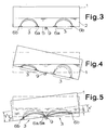
- the measuring electrodes 6 of the measuring sensors 3 are arranged flat on the bottom 5 of the container 1 and that the measuring sensors 3 are each designed as a stray field sensor with a stray field extending in the liquid 2 towards the liquid level. This can be seen particularly clearly in FIG. 3.
- the tilting axis 9 does not have to be physically present, it is always virtually present in the system, even if the container 1 in FIG. 4 is shifted parallel to itself, for example. It is essential that in principle a measuring sensor 3 is arranged on both sides of the "center". It can be seen from FIG. 3 that when the container 1 is level, the liquid level in the container 1 in the area of both measuring sensors 3 is at the same distance from the bottom 5, so that the stray fields measured are identical within the scope of the measuring and evaluation accuracy.
- FIG. 3 shows that when the container 1 is level, the liquid level in the container 1 in the area of both measuring sensors 3 is at the same distance from the bottom 5, so that the stray fields measured are identical within the scope of the measuring and evaluation accuracy.
- FIG. 5 makes it clear that in the case of the inclination measurement explained with reference to FIGS. 3 and 4, it is more favorable with regard to the evaluation if the normal level of the liquid 2 in the container 1 is as low as possible. It can be seen that the relative change x / y in FIG. 5 is considerably greater than the relative change x '/ y'. Thus, the farther the outer measuring electrodes 6b are from the measuring electrodes 6a in the middle and the lower the filling height, the higher the sensitivity, although the available angular measuring range is of course correspondingly smaller.
- An electrical measuring arrangement of the type explained above can be used in a self-contained manner as a measuring arrangement for other mechanical data.
- the container together with the liquid contained therein can itself form part of the measuring arrangement, so that other mechanical data, for example the inclination of the container with the liquid therein, a rotation of the container, a linear acceleration of the container and other mechanical data can be measured by measuring the behavior of the liquid in the container.
- the next step is the configuration according to FIG. 5, which is characterized in that the measuring electrodes 6a of the two measuring sensors 3 which are close to the tilt axis 9 are combined in a single electrode surface.
- This is, of course, a considerable simplification in terms of the circuit structure, it only being necessary to ensure that the electrode surface of the electrode forming the two measuring electrodes 6a is centered on the tilt axis 9, even if it is only virtually present.
- the measuring arrangements according to FIGS. 3 to 5 are only sensitive with respect to an inclination or tilting about the tilt axis 9, they are not sensitive to tilt or only very slightly sensitive to a tilt axis running perpendicular thereto. If you want to be able to measure inclinations about mutually perpendicular tilting axes, i.e. ultimately inclinations in all directions, it is recommended that in addition to the first pair of measuring sensors 3 a second pair of measuring sensors 3 is provided and angularly offset, preferably by 90 °, relative to the the first pair of measuring sensors 3 is arranged centered on the same center as the first pair of measuring sensors 3.
- FIG. 6 shows such a measuring arrangement with two pairs of measuring sensors 3, in which case it also applies that the measuring electrodes 6a of all measuring sensors 3 close to the center are combined in a single electrode surface.
- the angles indicated by the arc-shaped arrows are in each case 90 °.
- Fig. 7 shows the measuring arrangement from Fig. 6 with the schematically indicated substrate 10 with the applied measuring electrodes 6a, 6b, which have been produced in planar technology, with a generator 11, a first subtraction circuit 12 for the first pair of measuring sensors 3, a second Subtraction circuit 13 for the second pair of measuring sensors 3, a zero position detection stage 14 and an AND circuit 15.
- the inclination measurement signals for the x direction are at the top and for the y direction at the bottom.
- a signal is only output at the middle output when the container 1 is exactly in a horizontal orientation, that is to say there is no inclination in any direction. This is one way of carrying out the corresponding evaluation using the evaluation circuit 4.
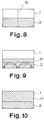
- Fig. 8 shows a further preferred embodiment in mechanical terms, which is characterized in that at least one separating element 16 is arranged or formed in the container 1, that through the separating element a certain, increased flow resistance for the liquid when flowing from one side of the separating element 16 to the other side of the separating element 16 and that a certain damping can be predetermined.
- the damping constant of the container 1 used here as the inclination sensor can be determined by the number and size of the openings in the isolating switch 16, which is designed here as a perforated plate.
- An alternative could also be to design the separating element 16 as a dividing wall with openings or as a double dividing wall with an underflow channel, that is to say to divide the container 1 into two parts with a flow connection of small cross-section.
- an acoustic evaluation signal can be triggered by the evaluation circuit 4, in particular that different evaluation signals can be triggered depending on the sign of the output signal indicating the direction of tilt.
- the stray field sensors of the type in question can be operated at temperatures up to approx. 600 K, at least if they are implemented in planar technology. Of course, you have to choose the right materials. For the rest, as has been explained at the beginning, one can use a purely conductivity sensor for calibration or standardization purposes Provide the stray field sensor used, but this is shown in detail in the figures.
- the evaluation circuit 4 is designed as evaluation electronics and, in particular, has a microprocessor or is integrated in a microprocessor.
- FIG. 10 shows a preferred or at least sometimes preferred form, in which the container 1 with the Liquid 2 and the auxiliary liquid 17 is completely filled. This sometimes has less of an impact.
- Fig. 11 now shows an application for a measuring arrangement according to the invention such that the container 1 in connection with a deformation in particular its inclination-changing deformation body 18 is inserted by the action of weight.
- the deformation body 18 is a bending rod, which can be used, for example, in a balance to hold a weight to be weighed.
- the angle of inclination is proportional to the force introduced into the deformation bodies 18, for example weight.
- the measuring arrangement used here according to the invention as an inclination sensor can have a very high sensitivity (for example 1 mV / 0.001 °).
- a very high sensitivity for example 1 mV / 0.001 °.
- the measuring arrangement to be used as an inclination sensor can also be used in conjunction with a deformation body 18 for deformation measurements as such, for example for measuring positional deviations in workpieces, buildings or bridges.
- a deformation body 18 for deformation measurements as such, for example for measuring positional deviations in workpieces, buildings or bridges.
- the detection of the inclination of the liquid level in the container 1 can be used in many other fields of application, for example for linear acceleration measurement, in the context of a rotation measurement in which the liquid level changes due to radial acceleration, correspondingly also for speed measurement etc.
- the miniaturization by the flat arrangement of the Measuring electrodes 6 of the measuring sensors 3 on the bottom 5 of the container 1, in particular in the context of planar technology on a substrate 10, are of very particular advantage.
Landscapes
- Physics & Mathematics (AREA)
- General Physics & Mathematics (AREA)
- Engineering & Computer Science (AREA)
- Radar, Positioning & Navigation (AREA)
- Remote Sensing (AREA)
- Thermal Sciences (AREA)
- Fluid Mechanics (AREA)
- Measurement Of Levels Of Liquids Or Fluent Solid Materials (AREA)
- Investigating Or Analyzing Materials By The Use Of Electric Means (AREA)
- Level Indicators Using A Float (AREA)
Abstract
Description
Die Erfindung betrifft eine elektrische Meßanordnung zur konduktometrischen Messung des Füllstandes oder daraus abgeleiteter mechanischer Daten einer in einem vorzugsweise geschlossenen Behälter befindlichen, elektrisch leitenden Flüssigkeit, die feststehende elektrische Eigenschaften aufweist, mit den Merkmalen des Oberbegriffs von Anspruch 1. Als Flüssigkeit kommt im Rahmen dieser Lehre insbesondere normal leitendes Wasser in Frage.The invention relates to an electrical measuring arrangement for the conductometric measurement of the fill level or mechanical data derived therefrom of an electrically conductive liquid which is in a preferably closed container and has fixed electrical properties, with the features of the preamble of
Die Erfindung bezieht sich auf eine elektrische Meßanordnung zur konduktometrischen Messung des Füllstandes, grenzt sich also gegenüber elektrischen Meßanordnungen zur kapazitiven Messung des Füllstandes ab. Nicht nur unmittelbar der Füllstand, sondern auch daraus abgeleitete mechanische Daten der Flüssigkeit, insbesondere also die Neigung des Flüssigkeitspiegels, können Ziel der Messung mit der beanspruchten elektrischen Meßanordnung sein. Der Begriff des Füllstandes einer in einem Behälter befindlichen Flüssigkeit macht dabei weiterhin deutlich, daß es sich um eine Flüssigkeit mit einem im wesentlichen ebenen Flüssigkeitsspiegel handeln muß, deren Füllstand im Behälter überhaupt als solcher gemessen werden kann.The invention relates to an electrical measuring arrangement for the conductometric measurement of the fill level, and is therefore different from electrical measuring arrangements for the capacitive measurement of the fill level. Not only the level directly, but also mechanical data of the liquid derived therefrom, in particular thus the inclination of the liquid level, can be the goal of the measurement with the claimed electrical measuring arrangement. The concept of the fill level of a liquid in a container also makes it clear that it must be a liquid with an essentially flat liquid level, the fill level of which can actually be measured as such in the container.
Ausgangspunkt für die Lehre der Erfindung ist eine elektrische Meßanordnung zur konduktometrischen Messung des Füllstandes einer in einem Behälter befindlichen Elektrolytflüssigkeit, die Sensorelektroden im Behälter benetzt (DE - A - 34 11 252). Mit dieser elektrischen Meßanordnung wird der Füllstand im hier oben offenen Behälter festgestellt und daraus die Neigung des Kraffahrzeugs, in dem dieser Behälter angeordnet ist, ermittelt. Wesentlich ist, daß sich an dieser Flüssigkeit im Behälter überhaupt ein Flüssigkeitsspiegel ausbildet, der Behälter also nur teilweise mit der Flüssigkeit gefüllt ist, so daß oberhalb der Flüssigkeit ein vollflächiger Freiraum verbleibt. Auch wenn der Behälter bei diesem Stand der Technik oben offen gezeigt ist, wird man häufig zur Vermeidung eines Flüssigkeitsverlustes den Behälter oben auch geschlossen ausführen.The starting point for the teaching of the invention is an electrical measuring arrangement for the conductometric measurement of the fill level of an electrolyte liquid located in a container, which wets sensor electrodes in the container (DE - A - 34 11 252). With this electrical measuring arrangement, the fill level in the container open up here is determined and from this the inclination of the vehicle in which this container is arranged is determined. It is essential that a liquid level is formed at all on this liquid in the container, that is to say the container is only partially filled with the liquid, so that a full-surface free space remains above the liquid. Even if the container in this prior art is shown open at the top, the container at the top will often also be closed to avoid loss of liquid.
Bei der bekannten, zuvor erläuterten elektrischen Meßanordnung sind zwei Meßsensoren realisiert, die jeweils zwei in einem bestimmten seitlichen Abstand voneinander liegende, mit der Flüssigkeit benetzte Meßelektroden aufweisen. Die Elektroden sind als Stabelektroden oder Plattenelektroden ausgeführt und tauchen von oben her senkrecht in die Flüssigkeit ein, und zwar über eine Länge, die mindestens gleich der maximalen Höhendifferenz des Flüssigkeitsniveaus am Ort der jeweiligen Meßelektode ist. Aus dem gemessenen Verhältnis der Widerstände läßt sich unmittelbar und kontinuierlich der Wert der Neigung des Flüssigkeitsspiegels ermitteln.In the known, previously explained electrical measuring arrangement, two measuring sensors are implemented, each of which has two measuring electrodes lying at a certain lateral distance from one another and wetted with the liquid. The electrodes are designed as stick electrodes or plate electrodes and plunge vertically into the liquid from above, over a length that is at least equal to the maximum height difference of the liquid level at the location of the respective measuring electrode. The value of the inclination of the liquid level can be determined directly and continuously from the measured ratio of the resistances.
Bei dem bekannten stand der Technik ist der Behälter um eine jedenfalls virtuell mittig am Boden des Behälters befindliche Kippachse kippbar, wobei die Meßsensoren beidseits der jedenfalls virtuell mittig liegenden Kippachse wirksam sind. Die Kippachse muß logischerweise nicht körperlich in der Mitte liegen, der Behälter kann schließlich auch um eine weitab liegende Kippachse kippen. Virtuell ist die Kippachse aber stets mittig am Boden des Behälters vorhanden, weil jede Kippung letztlich in eine Kippbewegung um die mittig am Boden virtuell vorhandene Kippachse und eine Verlagerung des Behälters parallel zu sich selbst zerlegt werden kann.In the known state of the art, the container can be tilted about a tilting axis which is in any case virtually in the center on the bottom of the container, the measuring sensors being effective on both sides of the tilting axis which is in any case virtually in the center. Logically, the tilt axis does not have to be physically in the middle, the container can finally tilt about a distant tilt axis. However, the tilting axis is virtually always present in the center of the bottom of the container, because each tilting can ultimately be broken down into a tilting movement around the tilting axis virtually present in the center of the bottom and a displacement of the container parallel to itself.
Die zuvor erläuterte Meßanordnung ist mit ihren Stab- oder Plattenelektroden konstruktiv relativ aufwendig und mechanisch relativ empfindlich. Aus weiterem Stand der Techik (GB - A - 993,715) ist eine elektrische Meßanordnung zur konduktometrischen Messung in einer in einem Behälter befindlichen, elektrisch leitenden Flüssigkeit bekannt, bei der die konduktometrische Messung mit zwei am Boden des Behälters angeordneten Meßsensoren mit jeweils zwei in einem bestimmten seitlichen Abstand voneinander liegenden, mit der Flüssigkeit kontaktierenden Meßelektroden erfolgt. Diese Meßelektroden sind am Boden des Behälters flächig angeordnet und bilden jeweils ein Streufeld in der Flüssigkeit aus. Diese bekannte elektrische Meßanordnung dient - ausschließlich - zur Neigunsmessung. Dazu ist der Behälter in bestimmter Weise geformt, nämlich bogenförmig gekrümmt nach Art einer Libelle. Das ist erforderlich, damit eine Luftblase in der Flüssigkeit immer definiert an der Decke des Behälters gegenüber dem Boden und den dort angeordneten Meßelektroden liegt.The measuring arrangement explained above is structurally relatively complex with its rod or plate electrodes and mechanically relatively sensitive. From another state of the art (GB - A - 993.715) an electrical measuring arrangement for conductometric measurement in an electrically conductive liquid located in a container is known, in which the conductometric measurement with two measuring sensors arranged on the bottom of the container, each with two in a particular one lateral spacing from each other, with the liquid contacting measuring electrodes. These measuring electrodes are arranged flat on the bottom of the container and each form a stray field in the liquid. This known electrical measuring arrangement is used exclusively for inclination measurement. For this purpose, the container is shaped in a certain way, namely curved in the manner of a dragonfly. This is necessary so that an air bubble in the liquid is always defined on the ceiling of the container opposite the floor and the measuring electrodes arranged there.
Von erheblicher Bedeutung ist es, daß hier nicht der Füllstand der im Behälter befindlichen Flüssigkeit gemessen wird. Ein solcher Füllstand ist hier überhaupt nicht definiert, da die Luftblase nur eine Innenfläche, nicht aber einen regelrechten Flüssigkeitsspiegel der Flüssigkeit im Behälter definiert. Das ist auch logisch, soll doch die Luftblase ihre Lage an der bogenförmigen Decke des Behälters je nach Neigung des Behälters nach links und rechts sichtbar verändern. Damit ist auch klar, daß sich das Streufeld über jeweils zwei Meßelektroden in der Flüssigkeit bis zur Decke des Behälters erstreckt, wenn die Luftblase sich aus diesem Bereich in den Bereich der anderen Meßelektroden hinüber bewegt hat. Die Einschnürung der Feldlinien des Streufeldes durch die in das Streufeld eintretende und die Flüssigkeit dort verdrängende Luftblase verändert den Stromfluß über die Meßelektroden und damit den letztlich extern gemessenen Leitwert.It is of considerable importance that the level of the liquid in the container is not measured here. Such a fill level is not defined here at all, since the air bubble only defines an inner surface, but not a regular liquid level of the liquid in the container. This is also logical, as the air bubble is supposed to change its position on the curved ceiling of the container depending on the inclination of the container to the left and right. It is also clear that the stray field extends over two measuring electrodes in the liquid to the ceiling of the container when the air bubble has moved from this area into the area of the other measuring electrodes. The constriction of the field lines of the stray field by the air bubble entering the stray field and displacing the liquid there changes the current flow through the measuring electrodes and thus the ultimately externally measured conductance.
Die Meßgenauigkeit einer elektrischen Meßanordnung mit Libelle wie in der GB - A - 993,715 dargestellt und beschriebenen, ist in erster Linie von der Formgebung des notwendigerweise gebogenen Behälters definiert. Die Meßgenauigkeit der aus dieser Entgegenhaltung bekannten elektrischen Meßanordnung zur konduktometrischen Messung einer Neigung wird durch folgende Faktoren begrenzt:The measuring accuracy of an electrical measuring arrangement with a level as shown and described in GB-A-993,715 is primarily defined by the shape of the necessarily curved container. The measuring accuracy of the electrical measuring arrangement known from this document for the conductometric measurement of an inclination is limited by the following factors:
Die Maßhaltigkeit des notwendigerweise gebogenen Behälters ist wichtig, bedingt aber hohe Herstellungskosten. Die Meßgenauigkeit ist durch die Reibung der Flüssigkeit insbesondere an der Decke des Behälters seitlich der Luftblase begrenzt. Da die Oberflächenspannung der Flüssigkeit im Bereich der Luftblase sich mitten in den Streufeldbereichen der Meßsensoren auswirkt, stellt dies eine wesentliche, die Meßgenauigkeit begrenzende Einflußgröße dar. Im Extremfall klebt die Luftblase bei nur geringer Neigungsänderung an der Decke des Behälters fest, so daß eine Neigungsmessung geringe Änderungen gar nicht erfaßt. Schließlich verändert sich die Größe der Luftblase mit der Temperatur mit starker Auswirkung auf das Meßergebnis.The dimensional accuracy of the necessarily curved container is important, but entails high manufacturing costs. The measuring accuracy is limited by the friction of the liquid, in particular on the ceiling of the container to the side of the air bubble. Since the surface tension of the liquid in the area of the air bubble has an effect in the middle of the stray field areas of the measuring sensors, this represents an important influencing variable that limits the measurement accuracy. In extreme cases, the air bubble sticks to the ceiling of the container with only a slight change in inclination, so that an inclination measurement is low Changes not recorded at all. Finally, the size of the air bubble changes with the temperature with a strong impact on the measurement result.
Der Erfindung liegt die Aufgabe zugrunde, die bekannte, eingangs erläuterte elektrische Meßanordnung zur konduktometrischen Messung des Füllstandes oder daraus abgeleiteter mechanischer Daten einer in einem Behälter befindlichen, elektrisch leitenden Flüssigkeit bei hoher Genauigkeit möglichst preisgünstig zu gestalten.The invention has for its object to make the known electrical measuring arrangement explained at the outset for the conductometric measurement of the fill level or mechanical data derived therefrom of an electrically conductive liquid contained in a container with high accuracy at low cost.
Die zuvor aufgezeigte Aufgabe ist bei einer Meßanordnung mit den Merkmalen des Oberbegriffs von Anspruch 1 durch die Merkmale des kennzeichnenden Teils von Anspruch 1 gelöst. Erfindungsgemäß wird die Konstruktion der elektrischen Meßanordnung dadurch wesentlich vereinfacht und die Robustheit der Meßanordnung erheblich verbessert, daß die Meßsensoren mit ihren Meßelektroden am Boden des Behälters flächig angeordnet sind. Die Ausrichtung und Befestigung der Meßelektroden der Meßsensoren ist damit von selbst über den Boden des Behälters (bei einer bevorzugten Ausführungsform überdies auch ergänzend über die Wand des Behälters) gewährleistet, damit ist die elektrische Meßanordnung außerordentlich robust und extrem kostengünstig herzustellen. Mit dieser Maßnahme gelingt es, eine elektrische Meßanordnung mit sehr hoher Meßgenauigkeit und trotzdem sehr geringen Kosten herzustellen.The above-mentioned object is achieved in a measuring arrangement with the features of the preamble of
Streufeldsensoren sind für sich seit langem für die Messung der elektrolytischen Leitfähigkeit einer Flüssigkeit bekannt (vgl. "messen + prüfen/automatik" Oktober 1976, 554, 563). Für die Theorie und Meßtechnik mit Streufeldsensoren wird daher auf diese Fachliteratur verwiesen. Wesentlich ist, daß ein als Streufeldsensor ausgeführter Meßsensor durchaus auch vier oder sechs Meßelektroden aufweisen kann, wenn man berücksichtigt, daß es aus meßtechnischen Gründen zweckmäßig ist, die Stromelektroden von den Spannungselektroden für die Potentialmessung zu trennen. Dadurch liegen Polarisationseffekte an den stromdurchflossenen Elektroden außerhalb der eigentlichen Meßstrecke mit den Spannungselektroden.Stray field sensors have long been known for measuring the electrolytic conductivity of a liquid (cf. "measure + test / automatic" October 1976, 554, 563). For theory and measurement technology with stray field sensors, reference is therefore made to this specialist literature. It is essential that a measuring sensor designed as a stray field sensor can also have four or six measuring electrodes if one takes into account that it is expedient for measuring reasons to separate the current electrodes from the voltage electrodes for the potential measurement. As a result, polarization effects on the current-carrying electrodes lie outside the actual measuring section with the voltage electrodes.
Funktionsnotwendig für die erfindungsgemäße elektrische Meßanordnung sind feststehende elektrische Eigenschaften der Flüssigkeit. Sind die elektrischen Eigenschaften der Flüssigkeit nicht bekannt oder schwanken sie, so kann zur Korrektur eine separater Meßsensor, insbesondere auch in Form eines Streufeldsensors, zu Kalibrierungszwecken vorgesehen sein, um also eine Normierung auf die jeweils gemessene Leitfähigkeit zu ermöglichen.Functional electrical properties of the liquid are necessary for the electrical measuring arrangement according to the invention. If the electrical properties of the liquid are not known or fluctuate, a separate measurement sensor, in particular also in the form of a stray field sensor, can be provided for calibration purposes for correction, so that it is possible to standardize the conductivity measured in each case.
Das Grundprinzip der Erfindung geht davon aus, daß die Meßelektroden der Meßsensoren in einer Ebene liegen. Grundsätzlich wäre es auch möglich, in einem Behälter zwei oder mehrere Meßsensoren mit jeweils zwei Meßelektroden oder drei Meßelektroden anzuordnen. Dann könnte man z. B. bei über 45° reichenden Neigungen von einem Meßsensor auf den anderen Meßsensor umschalten. Bei einem an allen Wandungen mit Meßsensoren bestückten Behälter könnte man eine Drehung des Behälters in jede beliebige Richtung durch Umschalten von einem Meßsensor auf den anderen Meßsensor meßtechnisch erfassen.The basic principle of the invention is based on the fact that the measuring electrodes of the measuring sensors lie in one plane. In principle, it would also be possible to arrange two or more measuring sensors in a container, each with two measuring electrodes or three measuring electrodes. Then you could e.g. B. switch over 45 ° inclinations from one measuring sensor to the other measuring sensor. In the case of a container equipped with measuring sensors on all walls, a rotation of the container in any direction could be measured by switching from one measuring sensor to the other measuring sensor.
Es gibt nun viele Möglichkeiten, die Lehre der Erfindung auszugestalten und weiterzubilden, wozu auf die dem Anspruch 1 nachgeordneten Ansprüche verwiesen werden darf.There are now many possibilities for developing and developing the teaching of the invention, for which purpose reference may be made to the claims subordinate to claim 1.
Im folgenden wird die Erfindung anhand einer lediglich Ausführungsbeispiele darstellenden Zeichnung näher erläutert. In der Zeichnung zeigt
- Fig. 1
- in schematischer Darstellung einen Behälter mit darin befindlicher Flüssigkeit und einer entsprechenden Meßanordnung,
- Fig. 2
- ein besonders bevorzugtes Ausführungsbeispiel eines Meßsensors gemäß der Erfindung,
- Fig. 2a
- in schematischer Darstellung in Draufsicht eine bestimmte Anordnung der Meßelektroden,
- Fig. 3
- in, hinsichtlich der Darstellungsart, Fig. 1 entsprechender Darstellung eine für eine Neigungsmessung abgeänderte erfindungsgemäße Meßanordnung,
- Fig. 4
- die Meßanordnung aus Fig. 3 mit geeignetem Behälter,
- Fig. 5
- die Meßanordnung aus Fig. 3 mit in die andere Richtung geneigtem Behälter, etwas anderer Anordnung der Meßelektroden und einer Darstellung des Einflusses unterschiedlich hoher Füllstände der Flüssigkeit für die Meßgenauigkeit,
- Fig. 6
- in Draufsicht ein Substrat einer in Planartechnik ausgeführten Meßanordnung mit vier Meßsensoren,
- Fig. 7
- die Meßanordnung aus Fig. 6 in schematischer Darstellung mit der dazu gehörenden Auswerteschaltung,
- Fig. 8
- in einer im Grundsatz Fig. 5 entsprechenden Darstellung ein Ausführungsbeispiel mit einer Trennwand im Behälter,
- Fig. 9
- in einer im Grundsatz Fig. 5 entsprechenden Darstellung ein Ausführungsbeispiel mit einer Hilfsflüssigkeit über der Flüssigkeit,
- Fig. 10
- in einer Fig. 9 entsprechenden Darstellung einen mit Flüssigkeit und Hilfsflüssigkeit vollständig gefüllten Behälter,
- Fig. 11
- ein Ausführungsbeispiel einer erfindungsgemäßen Meßanordnung in Verbindung mit einem Verformungskörper zur Neigungsmessung.
- Fig. 1
- a schematic representation of a container with liquid therein and a corresponding measuring arrangement,
- Fig. 2
- a particularly preferred embodiment of a measuring sensor according to the invention,
- Fig. 2a
- a certain arrangement of the measuring electrodes in a schematic representation in plan view,
- Fig. 3
- in a representation corresponding to the type of representation, FIG. 1, a measuring arrangement according to the invention modified for an inclination measurement,
- Fig. 4
- 3 with a suitable container,
- Fig. 5
- 3 with the container inclined in the other direction, somewhat different arrangement of the measuring electrodes and a representation of the influence of different levels of the liquid for the measuring accuracy,
- Fig. 6
- in plan view a substrate of a measuring arrangement implemented in planar technology with four measuring sensors,
- Fig. 7
- 6 in a schematic representation with the associated evaluation circuit,
- Fig. 8
- 5 shows an embodiment corresponding to the principle of FIG. 5 with a partition in the container,
- Fig. 9
- 5 shows an embodiment corresponding to the principle of FIG. 5 with an auxiliary liquid above the liquid,
- Fig. 10
- 9 shows a container completely filled with liquid and auxiliary liquid,
- Fig. 11
- an embodiment of a measuring arrangement according to the invention in connection with a deformation body for inclination measurement.
Fig. 1 zeigt zunächst die grundsätzliche Konstruktion einer elektrischen Meßanordnung zur Messung des Füllstandes oder auch anderer daraus abgeleiteter mechanischer Daten einer in einem Behälter 1 befindlichen, elektrisch leitenden Flüssigkeit 2, bei der es sich insbesondere um normal leitendes Wasser handeln kann. Im übrigen kann dieses System aber auch für alle anderen elektrisch leitenden Flüssigkeiten eingesetzt werden.Fig. 1 shows the basic construction of an electrical measuring arrangement for measuring the level or other mechanical data derived therefrom of an electrically
Die in Fig. 1 in einer prinzipiellen Darstellung gezeigte elektrische Meßanordnung weist einen Meßsensor 3 auf. Einem solchen Meßsensor 3 ist regelmäßig eine Auswerteschaltung 4 nachgeschaltet, wie sie im grundsätzlichen Blockschaltbild beispielsweise in Fig. 7 dargestellt ist. Das ist alles aus dem Stand der Technik bekannt.The electrical measuring arrangement shown in FIG. 1 in a basic representation has a measuring
Fig. 1 zeigt, daß der Meßsensor 3 als Streufeldsensor mit zwei in einem bestimmten seitlichen Abstand voneinander liegende Meßelektroden 6a, 6b ausgeführt ist. Hier wo es um die Messung des Füllstandes der Flüssigkeit im Behälter 1 geht, sind die beiden Meßelektroden 6a, 6b in einer Ebene, nämlich am Boden 5 des Behälters 1 angeordnet. Sie haben also praktisch das gleiche Niveau, was die meßtechnische Auswertung vereinfacht. Angedeutet ist das sich in der Flüssigkeit 2 ausbildende Streufeld. Dadurch verändert sich der mit dem Meßsensor 3 gemessene Meßwert signifikant mit der Füllhöhe bzw. dem Füllstand der Flüssigkeit 2. Aus dem Füllstand kann man dann andere mechanische Daten der Flüssigkeit 2, beispielsweise deren Volumen, errechnen. Man kann anhand von Fig. 1 unschwer verstehen, daß die Meßelektroden 6a, 6b auch in unterschiedlichen Ebenen liegen können, insbesondere winklig zueinander, beispielsweise Meßelektrode 6a am Boden 5 des Behälters 1 und die andere Meßelektrode 6b an der Seitenwand des Behälters 1. Das kann unter bestimmten meßtechnischen Voraussetzungen ebenfalls zweckmäßig sein.Fig. 1 shows that the measuring
Um eine möglichst korrekte Erfassung des Füllstandes der Flüssigkeit 2 im Behälter 1 zu ermöglichen, sind in Fig. 1 die Meßelektroden 6 des Meßsensors 3 nahe der äußersten Rändern des Bodens 5 angeordnet. Es gilt im übrigen, daß die Darstellung von zwei Meßelektroden 6a, 6b nur eine prinzipielle Darstellung ist. Für sich bekannt ist es für Streufeldsensoren, aus meßtechnischen Gründen die Stromführung über die Elektroden von Spannungsmessung zu trennen, also mit Stromelektroden und Spannungselektroden zu arbeiten.In order to enable the filling level of the liquid 2 in the
Streufeldsensoren der in Rede stehenden Art können in besonders zweckmäßiger Weise in Planartechnik auf einem Substrat ausgeführt sein. Dazu können auf einem Substrat die elektrisch leitenden, flächigen Strukturen, vorzugsweise aufgebracht in Planartechnik, insbesondere in Dünnfilmtechnik, vorgesehen sein, wobei dann an bestimmten Stellen ein gegen die betroffene Flüssigkeit 2 beständiges Dielektrikum als Abdeckung in Planartechnik oder anderer Beschichtungstechnik aufgebracht wird.Stray field sensors of the type in question can be implemented in a particularly expedient manner in planar technology on a substrate. For this purpose, the electrically conductive, flat structures, preferably applied in planar technology, in particular in thin-film technology, can be provided on a substrate, in which case a dielectric resistant to the
Fig. 2 zeigt eine ganz bevorzugte Ausgestaltung eines Meßsensors 3, bei dem die eine Meßelektrode 6a eine im wesentlichen geschlossene kreisförmige Elektrodenfläche und die andere Meßelektrode 6b eine im Mittelpunkt des Kreisringes liegende, kreisförmige Elektrodenfläche bildet. Die Ränder der beiden Elektrodenflächen weisen einen erheblichen radialen Abstand voneinander auf. Man erkennt hier, daß die Zuleitungen 7 von der Anschlußfläche 8 auf dem hier nur gestrichelt dargestellten Substrat möglichst schmal gemacht werden, um die auftretenden Streufelder möglichst gering zu halten. Bei der dargestellten Anordnung der Meßelektroden 6 des Meßsensors 3 ist gewährleistet, daß das insgesamt ausgemessene Streufeld unabhängig von der Neigung des Behälters 1 nach jeder der möglichen Richtungen konstant bleibt.2 shows a very preferred embodiment of a measuring
Bislang ist nur das Funktionsprinzip einer elektrischen Meßanordnung mit im Prinzip einem Meßsensor 3, der ein Streufeld über den Meßelektroden 6 ausbildet, erläutert worden. Dazu bleibt noch zu erwähnen, daß die maximal meßbare Füllhöhe etwa das 3,0-fache des Abstandes der Meßelektroden 6 beträgt, wenn man eine ausreichende Meßgenauigkeit voraussetzt und wenn man die in Fig. 1 dargestellten, weit beabstandeten Meßelektroden 6 einsetzt. Bei der in Fig. 2 dargestellten Ausführungsform verringert sich zwar die meßbare maximale Füllhöhe auf ungefähr das 2,5-fache des Durchmessers der Meßelektrode 6a, dafür hat man dann aber den Vorteil der Neigungsabhängigkeit des Meßwertes.So far, only the functional principle of an electrical measuring arrangement with in principle a measuring
Im Rahmen der Erfindung ist Ausgangspunkt eine elektrische Meßanordnung mit mindestens zwei Meßsensoren 3 mit jeweils zwei in einem bestimmten seitlichen Abstand voneinander liegenden, mit der Flüssigkeit 2 kontaktierenden Meßelektroden 6a, 6b, bei der der Behälter 1 um eine jedenfalls virtell mittig am Boden 5 befindliche Kippachse 9 kippbar ist, beidseits der Kippachse 9 jeweils ein Meßsensor 3 angeordnet ist und die Meßwerte der beiden Meßsensoren 3 in der Auswerteschaltung 4 auswertbar sind. Diese Auswertung erfolgt in einem Differenz-Auswerteverfahren. Für die Lehre wensenlich ist dabei, daß die Meßelektroden 6 der Meßsensoren 3 am Boden 5 des Behälters 1 flächig angeordnet sind und daß die Meßsensoren 3 jeweils als Streufeldsensor mit einem sich in der Flüssigkeit 2 zum Flüssigkeitsspiegel hin erstreckenden Streufeld ausgeführt sind. Das läßt Fig. 3 besonders deutlich erkennen.Within the scope of the invention, the starting point is an electrical measuring arrangement with at least two measuring
Die Kippachse 9 muß nicht körperlich vorhanden sein, sie ist systemimmanent jedenfalls stets auch virtuell vorhanden, auch wenn man den Behälter 1 in Fig. 4 beispielsweise parallel zu sich selbst verlagert. Wesentlich ist, daß im Grundsatz beidseits der "Mitte" jeweils ein Meßsensor 3 angeordnet ist. Man erkennt aus Fig. 3, daß bei ebener Ausrichtung des Behälters 1 auch der Flüssigkeitsspiegel im Behälter 1 im Bereich beider Meßsensoren 3 im gleichen Abstand vom Boden 5 liegt, so daß im Rahmen der Meß- und Auswertegenauigkeit die gemessenen Streufelder identisch sind. In Fig. 4 erkennt man dementgegen, daß sich das Streufeld des Meßsensors 3 rechts wegen der Neigung des Behälters 1 erheblich vergrößert hat, während das Streufeld des links dargestellten Meßsensors 3 durch die Neigung des Behälters 1 eingeschnürt worden ist. Eine Auswertung mit der Auswerteschaltung 4 macht also beispielsweise eine Neigungsmessung für den Behälter 1 möglich. Das läßt sich in Lagebestimmungsystemen, in "elektronischen Wasserwaagen" usw. mit großem Vorteil einsetzen, insbesondere wenn man berücksichtigt, daß die Meßsensoren 3 in Planartechnik ausgeführt sein können, also auch miniaturisierbar sind.The tilting
Fig. 5 macht deutlich, daß es bei der anhand der Fig. 3 und 4 erläuterten Neigungsmessung hinsichtlich der Auswertung günstiger ist, wenn die normale Höhe des Füllstandes derr Flüssigkeit 2 im Behälter 1 möglichst gering ist. Man erkennt, daß die relative Änderung x/y in Fig. 5 erheblich größer ist als die relative Änderung x'/y'. Je weiter also die außen liegenden Meßelektroden 6b von den in der Mitte liegenden Meßelektroden 6a entfernt sind und je geringer die Füllhöhe ist, desto höher ist also die Meßempfindlichkeit, wenngleich der zur Verfügung stehende Winkel-Meßbereich natürlich entsprechend geringer ist.FIG. 5 makes it clear that in the case of the inclination measurement explained with reference to FIGS. 3 and 4, it is more favorable with regard to the evaluation if the normal level of the liquid 2 in the
Eine elektrische Meßanordnung der zuvor erläuterten Art kann in sich selbst geschlossen als Meßanordnung für sonstige mechanische Daten eingesetzt werden kann. Der Behälter samt der darin befindlichen Flüssigkeit kann selbst einen Teil der Meßanordnung bilden, so daß andere mechanische Daten, beispielsweise die Neigung des Behälters mit darin befindlicher Flüssigkeit, eine Rotation des Behälters, eine Linearbeschleunigung des Behälters und andere mechanische Daten meßtechnisch erfaßt werden können, jeweils indem das Verhalten der Flüssigkeit im Behälter meßtechnisch erfaßt wird.An electrical measuring arrangement of the type explained above can be used in a self-contained manner as a measuring arrangement for other mechanical data. The container together with the liquid contained therein can itself form part of the measuring arrangement, so that other mechanical data, for example the inclination of the container with the liquid therein, a rotation of the container, a linear acceleration of the container and other mechanical data can be measured by measuring the behavior of the liquid in the container.
Wie zuvor schon angesprochen worden ist, kann es sich im übrigen empfehlen, außer den Meßsensoeren 3 am Boden 5 des Behälters 1 gleichartige Meßsensoren 3 an mindestens einer Wand des Behälters 1 anzuordnen, um so auch über 45° reichende Neigungen durch Umschalten vom einen Meßsensor 3 auf den nächsten Meßsensor 3 erfassen zu können.As has already been mentioned, it can also be advisable, apart from the measuring
Um auftretende, die Messung verfälschende Streufelder zwischen verschiedenen Meßsensoren 3 zu vermeiden, empfiehlt es sich, daß die der Kippachse 9 nahen Meßelektroden 6a der beiden Meßsensoren 3 auf gleichem Potential liegen. Der nächste Schritt ist dabei dann die Ausgestaltung gemäß Fig. 5, die dadurch gekennzeichnet ist, daß die der Kippachse 9 nahen Meßelektroden 6a der beiden Meßsensoren 3 in einer einzigen Elektrodenfläche zusammengefaßt sind. Das ist natürlich eine vom Schaltungsaufbau her erhebliche Vereinfachung, wobei man nur darauf achten muß, daß die Elektrodenfläche der die beiden Meßelektroden 6a bildenden Elektrode auf die Kippachse 9, sei sie auch nur virtuell vorhanden, zentriert ist. Möglich ist es aber auch, mit quer angeordneten Meßelektroden zu arbeiten, wobei dann eine Meßelektrode 6a quer über die Kippachse 9 verläuft, wie in Fig. 2a schematisch darstellt.In order to avoid stray fields which falsify the measurement between
An sich sind die Meßanordnungen nach den Fig. 3 bis 5 nur hinsichtlich einer Neigung bzw. Kippung um die Kippachse 9 empfindlich, um eine dazu senkrecht verlaufende Kippachse sind sie nicht neigungsempfindlich oder nur sehr wenig neigungsempfindlich. Will man Neigungen um zueinander senkrecht verlaufende Kippachsen, also letztlich Neigungen in alle Richtungen messen können, so empfiehlt es sich, daß zusätzlich zu dem ersten Paar von Meßsensoren 3 ein zweites Paar von Meßsensoren 3 vorgesehen und winklig, vorzugsweise um 90°, versetzt gegenüber dem ersten Paar von Meßsensoren 3 auf denselben Mittelpunkt wie das erste Paar von Meßsensoren 3 zentriert angeordnet ist. Fig. 6 zeigt eine solche Meßanordnung mit zwei Paaren von Meßsensoren 3, wobei dann ergänzend gilt, daß die dem Mittelpunkt nahen Meßelektroden 6a aller Meßsensoren 3 in einer einzigen Elektrodenfläche zusammengefaßt sind. Im dargestellten Ausführungsbeispiel sind die durch die bogenförmigen Pfeile angedeuteten Winkel jeweils 90°, mit entsprechend abgeänderten Auswertungsprogrammen kann man natürlich auch mit nicht exakt im 90°-Winkel stehenden zwei Paaren von Meßsensoren 3 arbeiten.The measuring arrangements according to FIGS. 3 to 5 are only sensitive with respect to an inclination or tilting about the
Fig. 7 zeigt die Meßanordnung aus Fig. 6 mit dem schematisch angedeuteten Substrat 10 mit den aufgebrachten Meßelektroden 6a, 6b, die in Planartechnik hergestellt worden sind, mit einem Generator 11, einer ersten Subtraktionsschaltung 12 für das erste Paar von Meßsensoren 3, einer zweiten Subtraktionsschaltung 13 für das zweite Paar von Meßsensoren 3, einer Nullagen-Feststellstufe 14 und einer Und-Schaltung 15. An den durch die Pfeile dargestellten Ausgängen stehen die Neigungs-Meßsignale für die x-Richtung oben, für die y-Richtung unten an. An dem mittleren Ausgang wird ein Signal nur dann abgegeben, wenn sich der Behälter 1 exakt in horizontaler Ausrichtung befindet, also eine Neigung in keine Richtung gegeben ist. Das ist eine Möglichkeit, die entsprechende Auswertung mit der Auswerteschaltung 4 durchzuführen.Fig. 7 shows the measuring arrangement from Fig. 6 with the schematically indicated
Fig. 8 zeigt nun ein in mechanischer Hinsicht weiter bevorzugtes Ausführungsbeispiel, das dadurch gekennzeichnet ist, daß im Behälter 1 mindestens ein Trennelement 16 angeordnet oder ausgebildet ist, daß durch das Trennelement ein bestimmter, erhöhter Strömungswiderstand für die Flüssigkeit beim Strömen von einer Seite des Trennelementes 16 zur anderen Seite des Trennelementes 16 gegeben ist und daß so eine bestimmte Dämpfung vorgebbar ist. Die Dämpfungskonstante des hier als Neigungssensor verwendeten Behälters 1 läßt sich durch Anzahl und Größe der Öffnungen im Trennschalter 16, das hier als Lochblech ausgeführt ist, bestimmen. Eine Alternative könnte auch darin bestehen, das Trennelement 16 als Trennwand mit Öffnungen oder als Doppel-Trennwand mit einem Unterströmkanal auszuführen, den Behälter 1 also gewissermaßen in zwei Teile mit einer Strömungsverbindung kleinen Querschnittes aufzuteilen.Fig. 8 shows a further preferred embodiment in mechanical terms, which is characterized in that at least one separating
Für die meßtechnische Anwendungen empfiehlt es sich im übrigen, daß von der Auswerteschaltung 4 ein akustisches Auswertesignal auslösbar ist, insbesondere, daß je nach dem die Kipprichtung anzeigende Vorzeichen des Ausgangssignals unterschiedliche Auswertesignale auslösbar sind. Insbesondere kann man so beispielsweise bei einer elektronischen Wasserwaage "blind" arbeiten, was für Anwendungen von großem Vorteil ist. Im übrigen wären natürlich auch entsprechende optische Signale sinnvoll, wenn das im jeweiligen Anwendungsfall zweckmäßig erscheint.For metrological applications, it is recommended that an acoustic evaluation signal can be triggered by the
Generell lassen sich die Streufeldsensoren der in Rede stehenden Art, jedenfalls dann, wenn sie in Planartechnik ausgeführt sind, bei Temperaturen bis zu ca. 600 K betreiben. Man muß dafür natürlich dann schon die passenden Werkstoffe wählen. Im übrigen kann man, wie eingangs erläutern worden ist, zum Zwecke der Kalibrierung bzw. Normierung noch einen als reinen Leitfähigkeitssensor eingesetzten Streufeldsensor vorsehen, was allerdings in den Figuren im einzelnen dargestellt ist.In general, the stray field sensors of the type in question can be operated at temperatures up to approx. 600 K, at least if they are implemented in planar technology. Of course, you have to choose the right materials. For the rest, as has been explained at the beginning, one can use a purely conductivity sensor for calibration or standardization purposes Provide the stray field sensor used, but this is shown in detail in the figures.
Für die Auswerteschaltung gelten übliche schaltungstechnische Ausgestaltungmöglichkeiten. Insbesondere ist es zweckmäßig, daß die Auswerteschaltung 4 als Auswerteelektronik ausgeführt ist und, insbesondere, einen Mikroprozessor aufweist oder in einen Mikroprozessor integriert ist.The usual circuit design options apply to the evaluation circuit. In particular, it is expedient that the
Meßtechnisch kann es problematisch sein, daß die elektrisch leitende Flüssigkeit 2 in dem Behälter 1 an der Wandung des Behälters 1 anhaftet. Dadurch wird die Füllstandsmessung verfälscht. Diesen Adhäsionseffekt kann man dadurch beseitigen, daß man den Behälter 1 oberhalb der elektrisch leitenden Flüssigkeit 2 mit einer elektrisch nicht leitenden Hilfsflüssigkeit 17 auffüllt. Nur der Bereich der elektrisch leitenden Flüssigkeit 2 ist meßtechnisch wirksam. Der Rand der elektrisch leitenden Flüssigkeit 2 wird aber durch die elektrisch nicht leitende, darüber gefüllte Hilfsflüssigkeit 17 begradigt bzw. von Adhäsionskräften befreit. Natürlich gilt der Begriff "elektrisch leitend" im Vergleich mit dem Begriff "nicht elektrisch leitend" relativ, d. h. daß auch eine nur sehr gering leitende Hilfsflüssigkeit 17 unter Umständen zur Abdeckung der elektrisch leitenden Flüssigkeit 2 benutzt werden kann.In terms of measurement technology, it can be problematic that the electrically
Während Fig. 9 die zuvor erläuterte Abdeckung mit einer Hilfsflüssigkeit 17 insoweit zeigt, als der Behälter 1 nach wie vor dann nicht vollständig mit Flüssigkeit gefüllt ist, zeigt Fig. 10 eine bevorzugte oder jedenfalls manchmal zu bevorzugende Form, bei der der Behälter 1 mit der Flüssigkeit 2 und der Hilfsflüssigkeit 17 komplett gefüllt ist. Das läßt mitunter Störeffekte einen geringeren Einfluß haben. Man könnte auch vorsehen, den Behälter 1 oberhalb der Flüssigkeit 2 bzw. der Hilfsflüssigkeit 17 (praktisch) zu evakuieren, so daß sich oberhalb des Flüssigkeitsspiegels nur der Sättigungsdampfdruck der Flüssigkeit 2 bzw. der Hilfsflüssigkeit 17 einstellt. Hier ist ein entsprechend passender Druck im Restvolumen zu wählen.9 shows the previously explained cover with an
Fig. 11 zeigt nun einen Anwendungsfall für eine erfindungsgemäße Meßanordnung dergestalt, daß der Behälter 1 in Verbindung mit einem bei Verformung insbesondere durch Gewichtseinwirkung seine Neigung ändernden Verformungskörper 18 eingesetzt ist. Bei dem Verformungskörper 18 handelt es sich hier um einen Biegestab, der beispielsweise in einer Waage der Aufnahme eines zu wiegenden Gewichts dienen kann.Fig. 11 now shows an application for a measuring arrangement according to the invention such that the
Ordnet man den Behälter 1 der erfindungsgemäßen Meßanordnung am Verformungskörper 18 an, so ergibt sich der Neigungswinkel proportional zur in den Verformungskörpern 18 eingeleiteten Kraft, beispielsweise Gewichtskraft. Die erfindungsgemäß hier als Neigungssensor eingesetzte Meßanordnung kann eine sehr hohe Empfindlichkeit haben (beispielsweise 1 mV/0,001°). Von besonderer Bedeutung ist bei dieser elektrischen Meßanordnung die Tatsache, daß man mit dieser elektrischen Meßanordnung nicht nur die durch Gewichtseinwirkung verursachte Neigung des Behälters 1 meßtechnisch erfassen kann, sondern genauso bereits erfassen kann, ob sich die unbelastete Waage in der Horizontalen befindet. Bei entsprechender Gestaltung der Auswerteschaltung 4 wäre es beispielsweise denkbar, vor jeder eigentlichen Gewichtsmessung zunächst eine Überprüfung der Ausrichtung der Waage in der Horizontalen vorzunehmen und, bei Abweichung, eine eigenständige Kalibrierung durchzuführen.If the
Die als Neigungssensor einzusetzende Meßanordnung kann man in Verbindung mit einem Verformungskörper 18 auch für Verformungsmessungen als solche, beispielsweise für die Messung von Lageabweichungen bei Werkstücken, Gebäuden oder Brücken einsetzen. Es gibt hier sehr weite Anwendungsfelder.The measuring arrangement to be used as an inclination sensor can also be used in conjunction with a
Die Erfassung der Neigung des Flüssigkeitsspiegels im Behälter 1 kann in vielerlei anderen Anwendungsfeldern eingesetzt werden, beispielsweise zur Linear-Beschleunigungsmessung, im Rahmen einer Rotationsmessung, bei der sich durch Radialbeschleunigung der Flüssigkeitsspiegel verändert, entsprechend auch zur Drehzahlmessung etc. Die Miniaturisierbarkeit durch die flächige Anordnung der Meßelektroden 6 der Meßsensoren 3 am Boden 5 des Behälters 1, insbesondere im Rahmen der Planartechnik auf einem Substrat 10, ist dabei von ganz besonderem Vorteil.The detection of the inclination of the liquid level in the
Claims (21)
- An electrical measuring arrangement for the conductometric measurement of the level of an electrically conducting liquid (2) or of mechanical data derived therefrom, which liquid has fixed electrical properties and which is situated in a container (1) which is preferably closed, with at least two measuring sensors (3), each having two measuring electrodes (6a, 6b) situated at a definite lateral distance from each other and contacting the liquid (2), wherein the container (1) can be tilted about a tilting axis (9) situated at least virtually centrally on the base (5), wherein a measuring sensor (3) is disposed in each case on both sides of the tilting axis (9) and wherein the measured values from the two measuring sensors (3) can be evaluated in an evaluation circuit (4), characterised in that the measuring electrodes (6) of the measuring sensors (3) are disposed two-dimensionally at the base (5) of the container (1) and each of the measuring sensors (3) is designed as a scatter field sensor with a scatter field extending in the liquid (2) up to the liquid level.
- A measuring arrangement according to claim 1, characterised in that the container (1), together with the liquid (2) situated therein, is itself part of the measuring arrangement.
- A measuring arrangement according to claim 1 or 2, characterised in that the measuring electrodes (6a, 6b) of the measuring sensors (3) lie substantially in a plane.
- A measuring arrangement according to any one of claims 1 to 3, characterised in that in addition to the measuring sensors (3) at the base (5) of the container (1) measuring sensors (3) of the same type are disposed on at least one wall of the container (1).
- A measuring arrangement according to any one of claims 1 to 4, characterised in that the measuring electrodes (6) are disposed near the outermost edges of the base (5).
- A measuring arrangement according to any one of claims 1 to 4, characterised in that one measuring electrode (6a) forms a substantially closed circular annular electrode surface and the other measuring electrode (6b) forms a circular electrode surface situated at the centre of the circular annulus.
- A measuring arrangement according to any one of claims 1 to 6, characterised in that the measuring electrodes (6) are (each) formed on a substrate (10) by the planar technique.
- A measuring arrangement according to any one of claims 1 to 7, characterised in that the measuring electrodes (6a) of the two measuring sensors (3) which are near the tilting axis (9) are at the same potential.
- A measuring arrangement according to claim 8, characterised in that the measuring electrodes (6a) of the two measuring sensors (3) which are near the tilting axis (9) are included in a single electrode surface.
- A measuring arrangement according to any one of claims 1 to 9, characterised in that in addition to the first pair of measuring sensors (3) at the base (5) a second pair of measuring sensors (3) is provided at the base (5) and is disposed displaced at an angle, preferably by 90°, in relation to the first pair of measuring sensors (3) at the base (5), centred on the same centre as the first pair of measuring sensors (3) at the base (5).
- A measuring arrangement according to claim 10, characterised in that the measuring electrodes (6a) of all the measuring sensors (3) which are near to the centre are included in a single electrode surface.
- A measuring arrangement according to any one of claims 1 to 11, characterised in that at least one separating element (16) is disposed or formed in the container (1), that a definite, increased resistance to flow is created by the separating element (16) for the liquid when flowing from one side of the separating element (16), and that a definite degree of damping can thus be predetermined.
- A measuring arrangement according to claim 12, characterised in that the separating element (16) is designed as a perforated plate, as a partition wall with openings or as a double partition wall with an underflow channel.
- A measuring arrangement according to any one of claims 1 to 13, characterised in that different acoustic evaluation signals can be triggered by the evaluation circuit (4) depending on the algebraic sign of the output signal, which algebraic sign indicates the direction of tilting.
- A measuring arrangement according to any one of claims 1 to 14, characterised in that a measuring sensor (3) designed as a conductivity sensor, particularly in the form of a scatter field sensor also, is associated with the measuring sensors (3) for calibration purposes.
- A measuring arrangement according to any one of claims 1 to 15, characterised in that the evaluation circuit (4) is designed as an electronic processing unit and comprises a microprocessor or is integrated in a microprocessor.
- A measuring arrangement according to any one of claims 1 to 16, characterised in that the container (1) is filled above the electrically conducting liquid (2) with an electrically non-conducting auxiliary liquid (17) of lower specific gravity.
- A measuring arrangement according to claim 17, characterised in that the container (1) is completely filled with the liquid (2) and the auxiliary liquid (17).
- A measuring arrangement according to any one of claims 1 to 17, characterised in that the container (1) is evacuated above the liquid (2) or above the auxiliary liquid (17).
- A measuring arrangement according to any one of claims 1 to 19, characterised in that the evaluation circuit (4) is designed for recording a filling height profile.
- The use of an electrical measuring arrangement according to any one of claims 1 to 20 for the measurement of inclination.
Applications Claiming Priority (8)
| Application Number | Priority Date | Filing Date | Title |
|---|---|---|---|
| DE4007232 | 1990-03-07 | ||
| DE4007232 | 1990-03-07 | ||
| DE4028730 | 1990-09-10 | ||
| DE4028730 | 1990-09-10 | ||
| DE4031845 | 1990-10-08 | ||
| DE4031845 | 1990-10-08 | ||
| DE19904036262 DE4036262A1 (en) | 1990-03-07 | 1990-11-14 | Electrical measuring appts. for level of conductive liq. - uses measuring sensor and evaluating circuit for continuous measurement of level in container or other mechanical data |
| DE4036262 | 1990-11-14 |
Publications (3)
| Publication Number | Publication Date |
|---|---|
| EP0447810A2 EP0447810A2 (en) | 1991-09-25 |
| EP0447810A3 EP0447810A3 (en) | 1992-01-08 |
| EP0447810B1 true EP0447810B1 (en) | 1994-12-14 |
Family
ID=27434901
Family Applications (1)
| Application Number | Title | Priority Date | Filing Date |
|---|---|---|---|
| EP91102305A Expired - Lifetime EP0447810B1 (en) | 1990-03-07 | 1991-02-19 | Measuring device for filling level or other mechanical properties of electrically conductive liquid |
Country Status (5)
| Country | Link |
|---|---|
| US (1) | US5182947A (en) |
| EP (1) | EP0447810B1 (en) |
| AT (1) | ATE115717T1 (en) |
| DE (1) | DE59103838D1 (en) |
| ES (1) | ES2067064T3 (en) |
Families Citing this family (17)
| Publication number | Priority date | Publication date | Assignee | Title |
|---|---|---|---|---|
| EP0610050B1 (en) * | 1993-02-01 | 1998-12-30 | Lee/Maatuk Engineering, Inc. | Variable fluid and tilt level sensing probe system |
| GB9311187D0 (en) * | 1993-05-29 | 1993-07-14 | Schlumberger Ind Ltd | Fluid level sensing systems |
| US6058934A (en) * | 1995-11-02 | 2000-05-09 | Chiron Diagnostics Corporation | Planar hematocrit sensor incorporating a seven-electrode conductivity measurement cell |
| US5765434A (en) * | 1996-07-18 | 1998-06-16 | Scepter Scientific, Inc. | Capacitive water height gauge and method |
| GB2323671B (en) * | 1997-03-27 | 2001-03-14 | Eastman Kodak Co | Vessel contents sensor |
| WO1999010714A1 (en) * | 1997-08-25 | 1999-03-04 | Millennium Sensors Ltd. | A compensated capacitive liquid level sensor |
| US6539286B1 (en) | 1998-01-26 | 2003-03-25 | Micron Technology, Inc. | Fluid level sensor |
| NL1012197C2 (en) | 1999-05-31 | 2000-12-01 | Univ Delft Tech | Device for determining an amount of a liquid. |
| CA2454789C (en) * | 2001-07-18 | 2011-05-10 | Emanuel Peled | Fuel cell with proton conducting membrane and with improved water and fuel management |
| US6605947B2 (en) * | 2001-10-03 | 2003-08-12 | Yi-Chia Liao | Cup shape sensible container for detecting liquid property |
| US6684138B1 (en) * | 2002-05-31 | 2004-01-27 | Hwh Corporation | Dynamic platform leveling system |
| JP4742683B2 (en) * | 2005-06-02 | 2011-08-10 | ソニー株式会社 | Liquid detection device and liquid ejection device |
| WO2009029533A1 (en) | 2007-08-24 | 2009-03-05 | Zevex, Inc. | Ultrasonic air and fluid detector |
| EP2219533A4 (en) * | 2007-12-07 | 2013-12-18 | Zevex Inc | Method of inducing transverse motion in langevin type transducers using split electroding of ceramic elements |
| DE102009030658B4 (en) * | 2009-06-25 | 2011-09-01 | Carl Freudenberg Kg | mopping device |
| US9300409B1 (en) * | 2011-08-01 | 2016-03-29 | eentec, LLC | Rotational electrochemical seismometer using magnetohydrodynamic technology and related methods |
| US8549764B2 (en) * | 2011-09-23 | 2013-10-08 | Lexmark International, Inc. | Fluid tilt sensor within ink tank supply item for micro-fluid applications |
Citations (2)
| Publication number | Priority date | Publication date | Assignee | Title |
|---|---|---|---|---|
| DE2551798A1 (en) * | 1974-11-18 | 1976-05-26 | Sperry Rand Corp | ELECTRIC INCLINATION SENSOR |
| DE3411252A1 (en) * | 1984-03-27 | 1985-10-10 | Bayerische Motoren Werke AG, 8000 München | Inclination sensor |
Family Cites Families (31)
| Publication number | Priority date | Publication date | Assignee | Title |
|---|---|---|---|---|
| GB993715A (en) * | 1961-12-11 | 1965-06-02 | English Electric Co Ltd | Improvements in or relating to tilt-sensitive devices |
| DE1250146B (en) * | 1963-11-02 | 1967-09-14 | Norddeutsche Mende Rundfunk K G | DEVICE FOR QUANTITY OR LEVEL MEASUREMENT OF LIQUID, GASEOUS OR SOLID GOODS |
| DE1296811B (en) * | 1965-05-05 | 1969-06-04 | Holzer Walter | Metallic liquid container |
| US3515987A (en) * | 1967-10-20 | 1970-06-02 | Avco Corp | Coplanar dielectric probe having means for minimizing capacitance from stray sources |
| DE1780523A1 (en) * | 1968-09-25 | 1971-08-26 | Wolfgang Mueller | Device for monitoring the minimum amount of brake fluid permitted in a brake circuit of hydraulic motor vehicle brakes |
| US3671857A (en) * | 1970-04-29 | 1972-06-20 | Karlis Alfredovich Bergmanis | Device for measuring permittivity of materials |
| US3781672A (en) * | 1971-05-10 | 1973-12-25 | Drexelbrook Controls | Continuous condition measuring system |
| SU459680A1 (en) * | 1972-02-22 | 1975-02-05 | Киргизский Научно-Исследовательский Институт Водного Хозяйства | Level switch |
| AT348267B (en) * | 1973-12-20 | 1979-02-12 | Contraves Ag | FEELING ELEMENT TO DETERMINE THE DEVIATION FROM THE PLUMB |
| US3986110A (en) * | 1975-08-29 | 1976-10-12 | Surface Systems, Inc. | Water depth measuring device |
| US4135151A (en) * | 1977-12-14 | 1979-01-16 | Surface Systems, Inc. | Apparatus for detecting wet and icy surface conditions |
| US4851831A (en) * | 1981-05-13 | 1989-07-25 | Drexelbrook Engineering Co. | Two-wire level measuring instrument |
| SU976300A1 (en) * | 1981-07-27 | 1982-11-23 | Государственный научно-исследовательский институт теплоэнергетического приборостроения "НИИтеплоприбор" | Discrete loose material level gauge transducer |
| US4568874A (en) * | 1983-02-17 | 1986-02-04 | Drexelbrook Controls, Inc. | RF Admittance apparatus and method for monitoring the contents of a pipe |
| DE3308361A1 (en) * | 1983-03-09 | 1984-09-13 | WTW Wissenschaftlich-technische Werkstätten GmbH, 8120 Weilheim | Measuring cell for determining the electrolytic conductivity of milk |
| US4503622A (en) * | 1983-04-20 | 1985-03-12 | Sperry Corporation | Precision inclinometer with digital numerical readout |
| US4547972A (en) * | 1983-08-30 | 1985-10-22 | Sperry Corporation | Tilt sensor and monitoring system |
| US4531300A (en) * | 1984-05-07 | 1985-07-30 | Sperry Corporation | Electronic inclination gauge with acceleration compensation |
| DD226068A1 (en) * | 1984-05-28 | 1985-08-14 | Suhl Feinmesszeugfab Veb | CAPACITIVE TILT AND LEVEL MEASUREMENT DEVICE |
| NL8402241A (en) * | 1984-07-16 | 1986-02-17 | Philips Nv | DEVICE FOR DETERMINING THE MOMENTANE TILT OF A MOVING ARTICLE. |
| DE3617234A1 (en) * | 1986-05-22 | 1987-11-26 | Meyer Fa Rud Otto | Water or moisture indicator |
| US4845421A (en) * | 1986-10-10 | 1989-07-04 | Mineral Control Instrumentation Ltd. | Method and apparatus for measuring the moisture content of a substance |
| US4779353A (en) * | 1987-03-26 | 1988-10-25 | Schlumberger Technology Corporation | Tool for measuring inclination and rotation |
| DE3838660A1 (en) * | 1987-06-30 | 1989-04-27 | Walter Nicolai | Method for the measurement and monitoring of the volume of the displaced liquid in the displacement chamber of a volume change device, taking into account permissible angular deviations of the ground area plane (base) of the displacement chamber from the horizontal |
| IT1211347B (en) * | 1987-07-31 | 1989-10-18 | Fiat Auto Spa | MEASURING DEVICE FOR THE QUANTITY OF LIQUID CONTAINED IN A TANK |
| DE3725752A1 (en) * | 1987-08-04 | 1989-03-02 | Vdo Schindling | METHOD AND DEVICE FOR DISPLAYING THE LIQUID LEVEL IN A MOTOR VEHICLE TANK |
| JPH01126535A (en) * | 1987-11-12 | 1989-05-18 | Kao Corp | Method and apparatus for measuring content of skin moisture |
| EP0358788A1 (en) * | 1988-09-13 | 1990-03-21 | G. + G. Technics Ag | Electrolytic inclination sensor |
| JPH02150726A (en) * | 1988-12-01 | 1990-06-11 | Matsushita Electric Ind Co Ltd | Liquid quantity detecting device |
| DE3920246A1 (en) * | 1989-06-21 | 1991-01-03 | Seidel Hans Hermann | Liquid inclination sensor with electrical output signal - has container of liquid and gas with dielectric wall separating liquid from electrodes with differential impedance measuring circuit |
| US4994750A (en) * | 1989-07-14 | 1991-02-19 | Ohio Mattress Company Licensing & Components | Use of capacitance for protecting against overheating of a waterbed heater |
-
1991
- 1991-02-19 EP EP91102305A patent/EP0447810B1/en not_active Expired - Lifetime
- 1991-02-19 ES ES91102305T patent/ES2067064T3/en not_active Expired - Lifetime
- 1991-02-19 DE DE59103838T patent/DE59103838D1/en not_active Expired - Lifetime
- 1991-02-19 AT AT91102305T patent/ATE115717T1/en not_active IP Right Cessation
- 1991-03-06 US US07/664,982 patent/US5182947A/en not_active Expired - Lifetime
Patent Citations (2)
| Publication number | Priority date | Publication date | Assignee | Title |
|---|---|---|---|---|
| DE2551798A1 (en) * | 1974-11-18 | 1976-05-26 | Sperry Rand Corp | ELECTRIC INCLINATION SENSOR |
| DE3411252A1 (en) * | 1984-03-27 | 1985-10-10 | Bayerische Motoren Werke AG, 8000 München | Inclination sensor |
Also Published As
| Publication number | Publication date |
|---|---|
| DE59103838D1 (en) | 1995-01-26 |
| ES2067064T3 (en) | 1995-03-16 |
| ATE115717T1 (en) | 1994-12-15 |
| EP0447810A3 (en) | 1992-01-08 |
| US5182947A (en) | 1993-02-02 |
| EP0447810A2 (en) | 1991-09-25 |
Similar Documents
| Publication | Publication Date | Title |
|---|---|---|
| EP0447810B1 (en) | Measuring device for filling level or other mechanical properties of electrically conductive liquid | |
| DE3545630C2 (en) | ||
| DE69206770T2 (en) | Triaxial accelerometer | |
| CH673897A5 (en) | ||
| CH660522A5 (en) | ELECTRONIC LEVELING DEVICE. | |
| EP2106551A2 (en) | Multi-axle micromechanic acceleration sensor | |
| DD226068A1 (en) | CAPACITIVE TILT AND LEVEL MEASUREMENT DEVICE | |
| DE4329571A1 (en) | Capacitive AC inclination sensor for determining level of lubricating dielectric liquid of vehicle transmission - divides capacitor into two pairs of electrodes spaced by gaps in which liq. is located, which gaps communicate by principle of communicating tubes | |
| DE10060091B4 (en) | Micromechanical inertial sensor | |
| DE3744411C2 (en) | ||
| DE19717580C2 (en) | tilt sensor | |
| DE102005025908B3 (en) | Capacitative sensor to measure values, e.g. for vehicle tilts and automatic machines, has two electrode pairs with a moving component between them with measurement of difference capacities at part-capacitors formed by the electrode array | |
| DE60221103T2 (en) | Integrated gyroscope made of semiconductor material with at least one sensitive axis in the sensor plane | |
| DE4036262A1 (en) | Electrical measuring appts. for level of conductive liq. - uses measuring sensor and evaluating circuit for continuous measurement of level in container or other mechanical data | |
| EP0221016B1 (en) | Inclinometer | |
| WO2000028293A1 (en) | Capacitive measuring sensor and method for operating same | |
| DE19858828A1 (en) | Capacitive sensor | |
| DE4102805A1 (en) | CAPACITIVE ACCELERATION SENSOR | |
| DE3912444A1 (en) | Inclination angle measurement device - has two or more liquid capacitors, each with capacitance transducer | |
| EP1145025B1 (en) | Capacitive magnetic field sensor | |
| DE4305934B4 (en) | Arrangement of sensors for measuring the humidity | |
| DE10217859C1 (en) | Electronic inclinometer, e.g. for activating car alarm or for use in iron or washing machine, has construction resembling variable electrical condenser with pendulous rotor | |
| DE102008025236B4 (en) | Capacitive sensor and a method for producing a capacitive sensor | |
| DE102004046411B4 (en) | accelerometer | |
| DE3920246A1 (en) | Liquid inclination sensor with electrical output signal - has container of liquid and gas with dielectric wall separating liquid from electrodes with differential impedance measuring circuit |
Legal Events
| Date | Code | Title | Description |
|---|---|---|---|
| PUAI | Public reference made under article 153(3) epc to a published international application that has entered the european phase |
Free format text: ORIGINAL CODE: 0009012 |
|
| AK | Designated contracting states |
Kind code of ref document: A2 Designated state(s): AT BE CH DE DK ES FR GB GR IT LI LU NL SE |
|
| PUAL | Search report despatched |
Free format text: ORIGINAL CODE: 0009013 |
|
| 17P | Request for examination filed |
Effective date: 19911029 |
|
| AK | Designated contracting states |
Kind code of ref document: A3 Designated state(s): AT BE CH DE DK ES FR GB GR IT LI LU NL SE |
|
| 17Q | First examination report despatched |
Effective date: 19930505 |
|
| GRAA | (expected) grant |
Free format text: ORIGINAL CODE: 0009210 |
|
| AK | Designated contracting states |
Kind code of ref document: B1 Designated state(s): AT BE CH DE DK ES FR GB GR IT LI LU NL SE |
|
| PG25 | Lapsed in a contracting state [announced via postgrant information from national office to epo] |
Ref country code: GR Free format text: LAPSE BECAUSE OF FAILURE TO SUBMIT A TRANSLATION OF THE DESCRIPTION OR TO PAY THE FEE WITHIN THE PRESCRIBED TIME-LIMIT Effective date: 19941214 Ref country code: DK Effective date: 19941214 |
|
| REF | Corresponds to: |
Ref document number: 115717 Country of ref document: AT Date of ref document: 19941215 Kind code of ref document: T |
|
| REF | Corresponds to: |
Ref document number: 59103838 Country of ref document: DE Date of ref document: 19950126 |
|
| EAL | Se: european patent in force in sweden |
Ref document number: 91102305.9 |
|
| PGFP | Annual fee paid to national office [announced via postgrant information from national office to epo] |
Ref country code: SE Payment date: 19950203 Year of fee payment: 5 |
|
| ITF | It: translation for a ep patent filed | ||
| ET | Fr: translation filed | ||
| PG25 | Lapsed in a contracting state [announced via postgrant information from national office to epo] |
Ref country code: LU Free format text: LAPSE BECAUSE OF NON-PAYMENT OF DUE FEES Effective date: 19950228 |
|
| GBT | Gb: translation of ep patent filed (gb section 77(6)(a)/1977) |
Effective date: 19950214 |
|
| REG | Reference to a national code |
Ref country code: ES Ref legal event code: FG2A Ref document number: 2067064 Country of ref document: ES Kind code of ref document: T3 |
|
| PLBE | No opposition filed within time limit |
Free format text: ORIGINAL CODE: 0009261 |
|
| STAA | Information on the status of an ep patent application or granted ep patent |
Free format text: STATUS: NO OPPOSITION FILED WITHIN TIME LIMIT |
|
| 26N | No opposition filed | ||
| PG25 | Lapsed in a contracting state [announced via postgrant information from national office to epo] |
Ref country code: SE Effective date: 19960220 |
|
| PGFP | Annual fee paid to national office [announced via postgrant information from national office to epo] |
Ref country code: FR Payment date: 19960222 Year of fee payment: 6 |
|
| PG25 | Lapsed in a contracting state [announced via postgrant information from national office to epo] |
Ref country code: FR Effective date: 19971030 |
|
| REG | Reference to a national code |
Ref country code: FR Ref legal event code: ST |
|
| REG | Reference to a national code |
Ref country code: FR Ref legal event code: RN |
|
| REG | Reference to a national code |
Ref country code: FR Ref legal event code: IC |
|
| REG | Reference to a national code |
Ref country code: GB Ref legal event code: IF02 |
|
| PG25 | Lapsed in a contracting state [announced via postgrant information from national office to epo] |
Ref country code: IT Free format text: LAPSE BECAUSE OF NON-PAYMENT OF DUE FEES;WARNING: LAPSES OF ITALIAN PATENTS WITH EFFECTIVE DATE BEFORE 2007 MAY HAVE OCCURRED AT ANY TIME BEFORE 2007. THE CORRECT EFFECTIVE DATE MAY BE DIFFERENT FROM THE ONE RECORDED. Effective date: 20050219 |
|
| PG25 | Lapsed in a contracting state [announced via postgrant information from national office to epo] |
Ref country code: GB Free format text: LAPSE BECAUSE OF NON-PAYMENT OF DUE FEES Effective date: 20060219 |
|
| GBPC | Gb: european patent ceased through non-payment of renewal fee |
Effective date: 20060219 |
|
| REG | Reference to a national code |
Ref country code: GB Ref legal event code: 728V |
|
| REG | Reference to a national code |
Ref country code: GB Ref legal event code: 728Y |
|
| PGFP | Annual fee paid to national office [announced via postgrant information from national office to epo] |
Ref country code: CH Payment date: 20080118 Year of fee payment: 18 Ref country code: ES Payment date: 20080307 Year of fee payment: 18 |
|
| PGFP | Annual fee paid to national office [announced via postgrant information from national office to epo] |
Ref country code: GB Payment date: 20080227 Year of fee payment: 18 Ref country code: NL Payment date: 20080229 Year of fee payment: 18 |
|
| PGFP | Annual fee paid to national office [announced via postgrant information from national office to epo] |
Ref country code: AT Payment date: 20080125 Year of fee payment: 18 |
|
| PGFP | Annual fee paid to national office [announced via postgrant information from national office to epo] |
Ref country code: BE Payment date: 20080307 Year of fee payment: 18 |
|
| BERE | Be: lapsed |
Owner name: *HL PLANARTECHNIK G.M.B.H. Effective date: 20090228 |
|
| REG | Reference to a national code |
Ref country code: CH Ref legal event code: PL |
|
| GBPC | Gb: european patent ceased through non-payment of renewal fee |
Effective date: 20090219 |
|
| PG25 | Lapsed in a contracting state [announced via postgrant information from national office to epo] |
Ref country code: CH Free format text: LAPSE BECAUSE OF NON-PAYMENT OF DUE FEES Effective date: 20090228 Ref country code: LI Free format text: LAPSE BECAUSE OF NON-PAYMENT OF DUE FEES Effective date: 20090228 Ref country code: AT Free format text: LAPSE BECAUSE OF NON-PAYMENT OF DUE FEES Effective date: 20090219 |
|
| NLV4 | Nl: lapsed or anulled due to non-payment of the annual fee |
Effective date: 20090901 |
|
| PG25 | Lapsed in a contracting state [announced via postgrant information from national office to epo] |
Ref country code: NL Free format text: LAPSE BECAUSE OF NON-PAYMENT OF DUE FEES Effective date: 20090901 |
|
| PG25 | Lapsed in a contracting state [announced via postgrant information from national office to epo] |
Ref country code: BE Free format text: LAPSE BECAUSE OF NON-PAYMENT OF DUE FEES Effective date: 20090228 |
|
| REG | Reference to a national code |
Ref country code: ES Ref legal event code: FD2A Effective date: 20090220 |
|
| PG25 | Lapsed in a contracting state [announced via postgrant information from national office to epo] |
Ref country code: GB Free format text: LAPSE BECAUSE OF NON-PAYMENT OF DUE FEES Effective date: 20090219 |
|
| PGFP | Annual fee paid to national office [announced via postgrant information from national office to epo] |
Ref country code: IT Payment date: 20080326 Year of fee payment: 18 |
|
| PGRI | Patent reinstated in contracting state [announced from national office to epo] |
Ref country code: IT Effective date: 20091201 |
|
| PGFP | Annual fee paid to national office [announced via postgrant information from national office to epo] |
Ref country code: DE Payment date: 20091125 Year of fee payment: 20 |
|
| PG25 | Lapsed in a contracting state [announced via postgrant information from national office to epo] |
Ref country code: ES Free format text: LAPSE BECAUSE OF NON-PAYMENT OF DUE FEES Effective date: 20090220 |
|
| REG | Reference to a national code |
Ref country code: DE Ref legal event code: R071 Ref document number: 59103838 Country of ref document: DE |
|
| PGRI | Patent reinstated in contracting state [announced from national office to epo] |
Ref country code: IT Effective date: 20091201 |
|
| PG25 | Lapsed in a contracting state [announced via postgrant information from national office to epo] |
Ref country code: DE Free format text: LAPSE BECAUSE OF EXPIRATION OF PROTECTION Effective date: 20110219 |