EP0447750B1 - Brake system with at least one brake circuit - Google Patents
Brake system with at least one brake circuit Download PDFInfo
- Publication number
- EP0447750B1 EP0447750B1 EP91100622A EP91100622A EP0447750B1 EP 0447750 B1 EP0447750 B1 EP 0447750B1 EP 91100622 A EP91100622 A EP 91100622A EP 91100622 A EP91100622 A EP 91100622A EP 0447750 B1 EP0447750 B1 EP 0447750B1
- Authority
- EP
- European Patent Office
- Prior art keywords
- freinage
- pression
- une
- par
- dispositif
- Prior art date
- Legal status (The legal status is an assumption and is not a legal conclusion. Google has not performed a legal analysis and makes no representation as to the accuracy of the status listed.)
- Expired - Lifetime
Links
Images

Classifications
-
- B—PERFORMING OPERATIONS; TRANSPORTING
- B60—VEHICLES IN GENERAL
- B60T—VEHICLE BRAKE CONTROL SYSTEMS OR PARTS THEREOF; BRAKE CONTROL SYSTEMS OR PARTS THEREOF, IN GENERAL; ARRANGEMENT OF BRAKING ELEMENTS ON VEHICLES IN GENERAL; PORTABLE DEVICES FOR PREVENTING UNWANTED MOVEMENT OF VEHICLES; VEHICLE MODIFICATIONS TO FACILITATE COOLING OF BRAKES
- B60T8/00—Arrangements for adjusting wheel-braking force to meet varying vehicular or ground-surface conditions, e.g. limiting or varying distribution of braking force
-
- B—PERFORMING OPERATIONS; TRANSPORTING
- B60—VEHICLES IN GENERAL
- B60T—VEHICLE BRAKE CONTROL SYSTEMS OR PARTS THEREOF; BRAKE CONTROL SYSTEMS OR PARTS THEREOF, IN GENERAL; ARRANGEMENT OF BRAKING ELEMENTS ON VEHICLES IN GENERAL; PORTABLE DEVICES FOR PREVENTING UNWANTED MOVEMENT OF VEHICLES; VEHICLE MODIFICATIONS TO FACILITATE COOLING OF BRAKES
- B60T13/00—Transmitting braking action from initiating means to ultimate brake actuator with power assistance or drive; Brake systems incorporating such transmitting means, e.g. air-pressure brake systems
- B60T13/10—Transmitting braking action from initiating means to ultimate brake actuator with power assistance or drive; Brake systems incorporating such transmitting means, e.g. air-pressure brake systems with fluid assistance, drive, or release
- B60T13/66—Electrical control in fluid-pressure brake systems
Definitions
- the invention relates to a brake system with at least one brake circuit actuated by supplying brake pressure and with a mechanical, redundant brake pressure controlling brake pressure control device and an electrical brake pressure control device according to the preamble of claim 1.
- Such a brake system is operated primarily by the electrical brake pressure control device. In the event of a fault in the electrical brake pressure control device, the brake system remains functional by means of the redundant brake pressure controlled by the mechanical brake pressure control device.
- Such a brake system is known from DE 35 01 179 A1.
- the brake pressure modulator of this brake system is designed as a blocking device with regard to the redundant brake pressure. For this purpose it is designed in such a way that when it is actuated in the sense of increasing or constant brake pressure it blocks its passage for the redundant brake pressure and when it is actuated in the sense of falling brake pressure this passage opens and thereby enables the desired brake pressure drop via the mechanical brake pressure control device.
- the known brake system is to contain one or more elements which cause a particularly rapid drop in brake pressure, then it must, as can be seen, for example, from FIG Elements the required quick Brake pressure drop guaranteed.
- Such elements are, for example, an anti-lock system and an overlying electrical or hydraulic permanent brake, usually called a retarder.
- the invention has for its object to prepare a brake system of the type mentioned without an additional device for the use of elements that cause a particularly rapid pressure drop.
- test routines are provided in the known brake system, in which the brake pressure modulator is automatically actuated in the sense of falling brake pressure when the brake system is actuated.
- the redundant brake pressure can pass as brake pressure to the output of the brake pressure modulator during the test routines.
- a pressure sensor of the control electronics used to monitor the brake pressure then indicates the level at which the redundant brake pressure is available.
- the invention can be developed with simple means so that it enables continuous monitoring of the redundant brake pressure when the brake is actuated.
- the invention can be carried out in connection with all suitable pressure media.
- the invention can be carried out inexpensively largely using commercially available devices.
- the pressure control valve described in DE 30 38 797 A1 can be used; in another embodiment, the brake pressure modulator can be produced, for example, from a customary magnetic proportional valve and a customary two-circuit relay valve device.
- FIG. 1 shows in solid lines the basic design of a brake system of a towing vehicle with a brake circuit actuated by supplying brake pressure with an application device (1) and with a mechanical brake pressure control device (5) and an electrical brake pressure control device (6, 8, 11, 19). Air serves as the pressure medium.
- the mechanical brake pressure control device consists of the pressure part (5) of a brake value transmitter (7).
- the electrical brake pressure control device (6, 8, 11, 19) consists of an electrical part (6) of the brake value transmitter (7), control electronics (11, 19), to which a control circuit (11) and a brake pressure sensor (19) belong, and a brake pressure modulator (8).
- the brake pressure modulator (8) is connected to an inlet (3) with a pressure supply (4) and at its outlet (17) to the application device (1). It is magnet and pressure operated. For actuating the pressure, it has a control device which is connected via another input (9) to the output of the pressure part (5) of the brake value transmitter (7) and is consequently acted upon by the redundant brake pressure. For solenoid actuation, it has an actuating magnet, which is not described in more detail.
- the pressure modulator (8) connects the application device (1) to the pressure supply (4) until a brake pressure has built up in the application device (1). the amount of which is measured both by the magnetic current supplied and by the level of the redundant brake pressure.
- the brake pressure emitted by the brake pressure modulator (8) is therefore composed of a brake pressure component based on the redundant brake pressure and on a brake pressure component.
- the brake pressure component due to the redundant brake pressure can be equal to or reduced or translated into the redundant brake pressure, i.e. lower or higher than the redundant brake pressure.
- the pressure control valve described in DE 30 38 797 A1 can be used as the brake pressure modulator (8). This is actuated by connecting its vent connection to the outlet of the pressure part (5) of the brake value transmitter (7) in the sense of the present invention.
- This brake pressure modulator measures the brake pressure by adding the brake pressure components due to its individual actuators. However, any other suitable type of brake pressure measurement can also be used.
- the pressure sensor (19) monitors the brake pressure modulator (8) at the output (17) of the brake pressure modulator (8) and supplies the control circuit (11) with a corresponding brake pressure signal.
- the brake value transmitter (7) When actuated by the driver, the brake value transmitter (7) emits on its electrical part (6) an electrical signal which is dependent on the actuating force or the actuation path, hereinafter referred to as the actuation signal; at the same time he controls on his pressure part (5) from the pressure supply (4) the redundant brake pressure, which also depends on the actuation variables mentioned.
- the brake pressure control device represented by the pressure part (5) is called "mechanical" because it converts the actuation variables introduced into the brake value transmitter (7) in a known manner with mechanical means into the redundant brake pressure.
- the control circuit (11) receives the actuation signal of the electrical part (6) of the brake value transmitter (7) and the brake pressure signal of the pressure sensor (19) and emits the magnet current required for its actuation to the magnet actuation of the brake pressure modulator (8).
- the control circuit (11) evaluates the actuation signal as a brake pressure request signal, compares it with the brake pressure signal and, in the event of a deviation, sets the magnet current to that for eliminating the deviation, i.e. to a value required to cover the respective brake pressure requirement.
- the control circuit (11) adjusts the magnet current so that the brake pressure component due to the magnet actuation makes up precisely the difference between the brake pressure request and the brake pressure component due to the redundant brake pressure.
- the electrical brake pressure control device (6, 8, 11, 19) and / or the mechanical brake pressure control device (8) can be designed such that, at least in the partial brake area, the brake pressure requirement is higher than the redundant brake pressure, so that at least in the partial brake area there is always one due to the magnet actuation Brake pressure component occurs and during full braking the brake value transmitter (7) requires a significantly increased actuation force or a significantly increased actuation path to control the full supply pressure as a redundant brake pressure.
- control circuit (11) can also store a target range for the mutual assignment of magnetic current strength and brake pressure when the pressure part (5) and the pressure actuation of the brake pressure modulator (8) function properly.
- control circuit (11) can also be designed such that, using the brake pressure signal, it determines the position of the magnetic current with respect to the desired range and emits a warning signal when the magnetic current leaves the desired range.
- control electronics (11, 19) can also be used to monitor the redundant brake pressure and thus the pressure part (5) and the pressure actuation of the pressure modulator (8) for intactness, because a magnetic current that falls outside the target range indicates that the pressure is too high or too low a brake pressure component due to the redundant brake pressure and thus to faults in the pressure part (5) and / or the pressure actuation of the pressure modulator (8) and / or associated pressure medium lines.
- FIG. 1 shows dashed lines of further further developments of the invention.
- a further application device (21) indicates that the brake circuit can also have several application devices.
- the further application devices can, as shown, on the brake pressure modulator (8) Basic equipment can be connected, but it can also be provided for each individual brake pressure modulators or their own brake pressure modulators.
- Control valves (2) and (20) of an anti-lock system not shown in the rest, hereinafter referred to as ABS valves, indicate that the brake system can also be equipped with an anti-lock system.
- the brake pressures in the application device (s) (1) or (21) and at the outlet (17) of the brake pressure modulator (8) can be different.
- Their control electronics can be wholly or partly combined with the control circuit (11).
- the ABS valves (2) and (20) have their own ventilation device in a known manner. As shown, they are arranged between the outlet (17) of the pressure modulator (8) and the application device (s) (1, 21). Therefore, if necessary, they enable a brake pressure drop in the application device (s) (1, 21) in the shortest possible way and therefore very quickly without any additional devices.
- the reference number (10) indicates at least one further signal transmitter, the signal of which the control circuit (11) evaluates in addition to the actuation signal of the electrical part (6) of the brake value transmitter (7) when determining the brake pressure request.
- One or more load sensors may be considered as such signal generators, for example, if the electrical brake pressure control device to be designated in this case with (6, 8, 10, 11, 19) contains a load-dependent brake pressure regulator.
- Additional or alternative signal transmitters include, for example, one or more retarder sensor (s), drawbar force sensor (s), Braking torque sensor (s), braking temperature sensor (s) and the like into consideration. In this training it can happen that the brake pressure component due to the redundant brake pressure already exceeds the braking force requirement. Adaptation is possible by arranging a restraint device indicated by (18) in the mechanical brake pressure control device, which is then designated by (5, 18), which restraint device (18) retains the redundant brake pressure up to a predetermined restraint pressure.
- the retention pressure can be a fixed pressure value or variable depending on the requirements of the specific application.
- a fixed pressure value is obtained when using a conventional overflow valve as a retention device.
- a variable retention pressure can be achieved, for example, by using a retention device according to the principles of the adaptation valves according to WABCO publications 975 001, March 1977 edition, or 975 002, August 1973 edition.
- Another exemplary possibility of making the restraint pressure variable is the design of the restraint device according to the principle of the load / empty valve shown in WABCO publication 973 300, January 1974 edition. In this case, as shown, the brake pressure could be supplied to the control input of the load / empty valve. If the electrical brake pressure control device contains a load-dependent brake pressure regulator, this configuration can be tailored specifically to this by designing the load / empty valve so that the retention pressure is at most equal to the brake pressure output by the brake pressure modulator (8) when the vehicle is empty.
- the entire brake pressure area can also be divided into a sub-area with wear-optimized braking and a sub-area in which it is more important to utilize the existing braking potential.
- the redundant brake pressure is below in the first section and above the restraining pressure in the second section.
- the exemplary embodiment contains a device for controlling a trailer brake system.
- This consists of a supply line (12) with a supply coupling (13) and an electrical and a pressure-actuated control device.
- the electrical control device consists of a control connection (14) and the control circuit (11), which is further developed for this purpose so that it receives the actuation signal received by the electrical part (6) of the brake value transmitter (7) and, if necessary, a part of the or converts all signal transmitters (10) into a trailer brake signal.
- the pressure-actuated control device consists of a trailer control valve (16) and an additional brake pressure modulator.
- the trailer control valve (16) corresponds to the usual pressure-actuated types.
- the additional brake pressure modulator basically corresponds to the brake pressure modulator (8) described above, but is partly installed differently from that; it is connected at its first inlet (3) to the supply line (12) and at its outlet (17) to a pressure control device of the trailer control valve (16). In a manner not shown, the output (17) of the additional brake pressure modulator (8) can also be connected directly to the trailer brake line.
- the magnetic actuation of this brake pressure modulator (8) is also supplied with magnetic current by the correspondingly designed control circuit (11).
- the training consists in the fact that the brake circuit contains a relay valve (25), which is connected upstream of the application device (1) or application devices (1, 21) in a conventional manner and whose control device is supplied with the brake pressure emitted by the brake pressure modulator (8) as control pressure becomes.
- the brake pressure sensor (19) is shown at the output of the brake pressure modulator (8), but can also be arranged at the output of the relay valve (25).
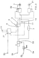
- Figure 3 shows in solid lines the basic design of a braking system of a trailer.
- the mechanical brake pressure control device (33, 34) in this case consists of a trailer brake valve (33) and a load-dependent brake pressure regulator (34). Both are of known types and arranged in the usual way. Consequently, the trailer brake valve (33) also serves to transfer the pressure medium supplied from the towing vehicle via a supply coupling (36) to the pressure supply (4) and it is arranged via a brake coupling (35) and a control line in which the load-dependent brake pressure regulator (3) is also arranged is driven.
- the load-dependent brake pressure regulator (34) can also be omitted.
- the electrical brake pressure control device (30, 8, 31, 19) consists of an electrical control connection (30), the control electronics (31, 19), to which a control circuit (31) and a pressure sensor (19) belong, and a brake pressure modulator.
- the brake pressure modulator, again designated by (8), and the brake pressure sensor, again designated by (19), correspond in principle to the components of the earlier exemplary embodiment that are identified by the same name.
- the control connection (30) receives the trailer brake signal generated in the towing vehicle and feeds it to the control circuit (31).
- the brake pressure modulator (8) is connected at one input (3) to the pressure supply (4) and at its other input (9) to the output of the trailer brake valve (33).
- the brake value modulator (8) is connected to the pressure control device of a relay valve (32), which also has a solenoid actuation and is thereby also a solenoid-controlled control valve of an anti-lock system.
- a relay valve also called ABS relay valve
- ABS relay valve is described for example in DE 37 30 779 A1.
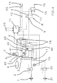
- FIG. 4 shows the exemplary embodiment according to FIG. 1 with a different embodiment of the brake pressure modulator.
- the brake pressure modulator generally designated here with (41), consists of a two-circuit relay valve device (44) and a solenoid-operated valve device (40).
- the two-circuit relay valve device (44) is of a commercially available top-up type. In this context, “topping up” means that when its two control devices are pressurized at the same time, it releases a higher pressure at its outlet than when only one of its control devices is pressurized.
- the valve device (40) is designed in a known manner in such a way that it modulates a pressure which is dependent on the magnetic current strength supplied.
- a commercially available magnetic proportional valve can be used, for example.
- a line comprising both of the aforementioned valve devices (40) and (44) indicates that these are assembled to form the brake pressure modulator (41).
- they can also perform the function of the brake pressure modulator (41) as individual devices that are connected to one another on the pressure side.
- One input (3), the other input (9) and the output (17) of the brake pressure modulator (41) are shown as connection points of the corresponding pressure medium lines to the mentioned line; If the valve device (40) and the two-circuit relay valve device (44) are arranged separately, the inputs (3) and (9) and the output (17) can coincide with connections of the valve device (40) and the two-circuit relay valve device (44).
- the valve device (40) is connected to one inlet (3) at its pressure medium inlet.
- the two-circuit relay valve device (44) is also connected to one input (3) at its supply connection, at one control device (42) to the outlet of the valve device (40), at its other control device (43) to the second input (9). and connected at its output to the output (17).
- the actuating magnet of the valve device (40) represents the magnet actuation of the brake pressure modulator (41).
- the two-circuit relay valve device (44 ) controlled both by the pressure controlled by the valve device (40) and by the pressure emitted by the mechanical brake pressure control device (5) or (5, 18). Since the pressure emitted by the valve device (40) depends on the current strength supplied to the actuating magnet, the control of the two-circuit relay valve device (44) on the control device (42) is dependent on this magnetic current strength.
- valve device (40) and the two-circuit relay valve device (44) provide the same functions in connection with one another as the brake pressure modulator (8) of the exemplary embodiment according to FIG. 1.
- the brake pressure modulator (8) can also be used in the others mentioned above Arrangements and in general, possibly with simple adaptation measures, are replaced by the brake pressure modulator (41).
Landscapes
- Engineering & Computer Science (AREA)
- Transportation (AREA)
- Mechanical Engineering (AREA)
- Regulating Braking Force (AREA)
- Braking Systems And Boosters (AREA)
- Valves And Accessory Devices For Braking Systems (AREA)
Description
Die Erfindung betrifft eine Bremsanlage mit wenigstens einem durch Zuführung von Bremsdruck betätigten Bremskreis sowie mit einer mechanischen, redundanten Bremsdruck aussteuernden, Bremsdrucksteuereinrichtung und einer elektrischen Bremsdrucksteuereinrichtung gemäß dem Oberbegriff des Patentanspruchs 1.The invention relates to a brake system with at least one brake circuit actuated by supplying brake pressure and with a mechanical, redundant brake pressure controlling brake pressure control device and an electrical brake pressure control device according to the preamble of
Eine derartige Bremsanlage wird vorrangig durch die elektrische Bremsdrucksteuereinrichtung betätigt. Bei einer Störung in der elektrischen Bremsdrucksteuereinrichtung bleibt die Bremsanlage mittels des von der mechanischen Bremsdrucksteuereinrichtung ausgesteuerten redundanten Bremsdrucks funktionsfähig.Such a brake system is operated primarily by the electrical brake pressure control device. In the event of a fault in the electrical brake pressure control device, the brake system remains functional by means of the redundant brake pressure controlled by the mechanical brake pressure control device.
Eine derartige Bremsanlage ist aus der DE 35 01 179 A1 bekannt. Der Bremsdruckmodulator dieser Bremsanlage ist hinsichtlich des redundanten Bremsdrucks als Sperreinrichtung ausgebildet. Er ist zu diesem Zweck so ausgestaltet, daß er bei Betätigung im Sinne steigenden oder gleichbleibenden Bremsdrucks seinen Durchgang für den redundanten Bremsdruck sperrt und bei Betätigung im Sinne fallenden Bremsdrucks diesen Durchgang öffnet und dadurch über die mechanische Bremsdrucksteuereinrichtung den angestrebten Bremsdruckabfall ermöglicht.Such a brake system is known from DE 35 01 179 A1. The brake pressure modulator of this brake system is designed as a blocking device with regard to the redundant brake pressure. For this purpose it is designed in such a way that when it is actuated in the sense of increasing or constant brake pressure it blocks its passage for the redundant brake pressure and when it is actuated in the sense of falling brake pressure this passage opens and thereby enables the desired brake pressure drop via the mechanical brake pressure control device.
Soll die bekannte Bremsanlage ein oder mehrere Elemente enthalten, die einen besonders schnellen Bremsdruckabfall bedingen, so muß sie, wie zum Beispiel aus Fig.2 der DE 35 01 179 A1 hervorgeht, eine elektrisch gesteuerte Ventileinrichtung aufweisen, die beim Betrieb dieses Elements bzw. dieser Elemente den erforderlichen schnellen Bremsdruckabfall gewährleistet. Derartige Elemente sind beispielsweise eine Blockierschutzanlage und eine überlagernde elektrische oder hydraulische Dauerbremse, üblicherweise Retarder genannt.If the known brake system is to contain one or more elements which cause a particularly rapid drop in brake pressure, then it must, as can be seen, for example, from FIG Elements the required quick Brake pressure drop guaranteed. Such elements are, for example, an anti-lock system and an overlying electrical or hydraulic permanent brake, usually called a retarder.
Der Erfindung liegt die Aufgabe zugrunde, eine Bremsanlage der eingangs genannten Art ohne eine zusätzliche Einrichtung für den Einsatz von Elementen, die einen besonders schnellen Druckabfall bedingen, vorzubereiten.The invention has for its object to prepare a brake system of the type mentioned without an additional device for the use of elements that cause a particularly rapid pressure drop.
Diese Aufgabe wird durch die in dem Patentanspruch 1 angegebene Erfindung gelöst. Vorteilhafte Ausgestaltungen und Weiterbildungen sind in den Unteransprüchen angegeben.This object is achieved by the invention specified in
Zur Erfindung gehört, die Magnetstromstärke so einzustellen, daß die auf die Magnetbetätigung zurückgehende Bremsdruckkomponente gerade den Unterschied zwischen der Bremsdruckanforderung und der auf den redundanten Bremsdruck zurückgehenden Bremsdruckkomponente ausmacht.It is part of the invention to set the magnetic current so that the brake pressure component due to the magnet actuation makes the difference between the brake pressure request and the brake pressure component due to the redundant brake pressure.
Zur Überwachung des redundanten Bremsdrucks sind in der bekannten Bremsanlage Testroutinen vorgesehen, in denen bei betätigter Bremsanlage der Bremsdruckmodulator selbsttäig im Sinne fallenden Bremsdrucks betätigt wird. Dadurch kann während der Testroutinen der redundante Bremsdruck als Bremsdruck zum Ausgang des Bremsdruckmodulators durchtreten. Ein zur Überwachung des Bremsdrucks dienender Drucksensor der Steuerelektronik zeigt dann an, in welcher Höhe der redundante Bremsdruck zur Verfügung steht.To monitor the redundant brake pressure, test routines are provided in the known brake system, in which the brake pressure modulator is automatically actuated in the sense of falling brake pressure when the brake system is actuated. As a result, the redundant brake pressure can pass as brake pressure to the output of the brake pressure modulator during the test routines. A pressure sensor of the control electronics used to monitor the brake pressure then indicates the level at which the redundant brake pressure is available.
Demgegenüber kann die Erfindung mit einfachen Mitteln so forgebildet werden, daß sie bei Bremsbetätigung eine kontinuierliche Überwachung des redundanten Bremsdrucks ermöglicht.In contrast, the invention can be developed with simple means so that it enables continuous monitoring of the redundant brake pressure when the brake is actuated.
Die Erfindung läßt sich in Verbindung mit allen geeigneten Druckmitteln ausführen.The invention can be carried out in connection with all suitable pressure media.
Die Erfindung läßt sich kostengünstig weitgehend unter Verwendung marktgängiger Geräte ausführen. So ist beispielsweise in einer Ausgestaltung als Bremsdruckmodulator das in der DE 30 38 797 A1 beschriebene Druckregelventil einsetzbar, in einer anderen Ausgestaltung der Bremsdruckmodulator beispielsweise aus einem üblichen Magnet-Proportionalventil und einer üblichen aufstockenden Zweikreis-Relaisventileinrichtung herstellbar.The invention can be carried out inexpensively largely using commercially available devices. For example, in one embodiment as a brake pressure modulator, the pressure control valve described in
Weitere Vorteile der Erfindung werden in deren nun folgender Erläuterung anhand von in Zeichnungen dargestellten Ausführungsbeipielen genannt.Further advantages of the invention are mentioned in the following explanation based on exemplary embodiments shown in the drawings.
Unter durchgehender Verwendung durchgezogener und gestrichelter Linien für Druckmittelleitungen und sonstige Bauteile sowie strichpunktierter Linien für elektrische Verbindungen sowie einheitlicher Bezugszeichen für Bauteile mit gleichen Funktionen zeigen:
- Fig.1
- eine Prinzipskizze einer Bremsanlage eines Zugfahrzeugs,
- Fig.2
- eine Fortbildung derselben,
- Fig.3
- eine Prinzipskizze einer Bremsanlage eines Anhängers,
- Fig.4
- Fig.1 mit einer anderen Ausgestaltung des Bremsdruckmodulators.
- Fig. 1
- a schematic diagram of a braking system of a towing vehicle,
- Fig. 2
- a training of the same,
- Fig. 3
- a sketch of a braking system of a trailer,
- Fig. 4
- 1 with another embodiment of the brake pressure modulator.
Fig.1 zeigt in durchgezogenen Linien schematisch die Grundausführung einer Bremsanlage eines Zugfahrzeugs mit einem durch Zuführung von Bremsdruck betätigten Bremskreis mit einer Zuspanneinrichtung (1) sowie mit einer mechanischen Bremsdrucksteuereinrichtung (5) und einer elektrischen Bremsdrucksteuereinrichtung (6, 8, 11, 19). Als Druckmittel dient Luft. Bei entsprechender Anpassung gelten die nachstehenden Ausführungen jedoch für andere Druckmittel einsetzende Bremsanlagen mit.1 shows in solid lines the basic design of a brake system of a towing vehicle with a brake circuit actuated by supplying brake pressure with an application device (1) and with a mechanical brake pressure control device (5) and an electrical brake pressure control device (6, 8, 11, 19). Air serves as the pressure medium. With a corresponding adjustment, however, the following explanations also apply to other brake systems using pressure medium.
Die mechanische Bremsdrucksteuereinrichtung besteht aus dem Druckteil (5) eines Bremswertgebers (7). Die elektrische Bremsdrucksteuereinrichtung (6, 8, 11, 19) besteht aus einem elektrischen Teil (6) des Bremswertgebers (7), einer Steuerelektronik (11, 19), zu der eine Steuerschaltung (11) und ein Bremsdrucksensor (19) gehören, und einem Bremsdruckmodulator (8).The mechanical brake pressure control device consists of the pressure part (5) of a brake value transmitter (7). The electrical brake pressure control device (6, 8, 11, 19) consists of an electrical part (6) of the brake value transmitter (7), control electronics (11, 19), to which a control circuit (11) and a brake pressure sensor (19) belong, and a brake pressure modulator (8).
Die erwähnten Bauteile der Bremsanlage sind mit Ausnahme der Steuerschaltung (11) von bekannten Bauarten.The components of the brake system mentioned are of known types with the exception of the control circuit (11).
Der Bremsdruckmodulator (8) ist an einem Eingang (3) mit einem Druckvorrat (4) und an seinem Ausgang (17) mit der Zuspanneinrichtung (1) verbunden. Er ist magnet- und druckbetätigt. Zur Druckbetätigung weist er eine Steuereinrichtung auf, die über einen anderen Eingang (9) mit dem Ausgang des Druckteils (5) des Bremswertgebers (7) verbunden und folglich mit dem redundanten Bremsdruck beaufschlagt ist. Zur Magnetbetätigung weist er einen nicht näher bezeichneten Betätigungsmagneten auf. Bei Betätigung durch eine der oder durch beide Betätigungseinrichtungen verbindet der Druckmodulator (8) die Zuspanneinrichtung (1) mit dem Druckvorrat (4), bis sich in der Zuspanneinrichtung (1) ein Bremsdruck aufgebaut hat, dessen Höhe sich sowohl nach dem zugeführten Magnetstrom als auch nach der Höhe des redundanten Bremsdrucks bemißt.The brake pressure modulator (8) is connected to an inlet (3) with a pressure supply (4) and at its outlet (17) to the application device (1). It is magnet and pressure operated. For actuating the pressure, it has a control device which is connected via another input (9) to the output of the pressure part (5) of the brake value transmitter (7) and is consequently acted upon by the redundant brake pressure. For solenoid actuation, it has an actuating magnet, which is not described in more detail. When actuated by one or by both actuation devices, the pressure modulator (8) connects the application device (1) to the pressure supply (4) until a brake pressure has built up in the application device (1). the amount of which is measured both by the magnetic current supplied and by the level of the redundant brake pressure.
Der von dem Bremsdruckmodulator (8) abgegebene Bremsdruck setzt sich also aus einer auf den redundanten Bremsdruck und aus einer auf die Magnetbetätigung zurückgehenden Bremsdruckkomponente zusammen. Je nach Ausgestaltung der zur Druckbetätigung vorgesehenen Steuereinrichtung des Bremsdruckmodulators (8) kann die auf den redundanten Bremsdruck zurückgehende Bremsdruckkomponente dem redundanten Bremsdruck gleich oder diesem gegenüber untersetzt oder übersetzt, d.h. geringer oder höher als der redundante Bremsdruck, sein.The brake pressure emitted by the brake pressure modulator (8) is therefore composed of a brake pressure component based on the redundant brake pressure and on a brake pressure component. Depending on the configuration of the control device of the brake pressure modulator (8) provided for the pressure actuation, the brake pressure component due to the redundant brake pressure can be equal to or reduced or translated into the redundant brake pressure, i.e. lower or higher than the redundant brake pressure.
Als Bremsdruckmodulator (8) kann beispielsweise das in der DE 30 38 797 A1 beschriebene Druckregelventil eingesetzt werden. Dieses wird durch Verbindung seines Entlüftungsanschlusses mit dem Ausgang des Druckteils (5) des Bremswertgebers (7) im Sinne der vorliegenden Erfindung druckbetätigt. Dieser Bremsdruckmodulator bemißt den Bremsdruck durch Addition der auf seine einzelnen Betätigungseinrichtungen zurückgehenden Bremsdruckkomponenten. Es ist aber auch jede geeignete andere Art der Bremsdruckbemessung einsetzbar.The pressure control valve described in
Der Drucksensor (19) überwacht am Ausgang (17) des Bremsdruckmodulators (8) den von diesem an die Zuspanneinrichtung (1) abgegebenen Bremsdruck und liefert der Steuerschaltung (11) ein entsprechendes Bremsdrucksignal.The pressure sensor (19) monitors the brake pressure modulator (8) at the output (17) of the brake pressure modulator (8) and supplies the control circuit (11) with a corresponding brake pressure signal.
Der Bremswertgeber (7) gibt bei Betätigung durch den Fahrer an seinem elektrischen Teil (6) ein von der Betätigungskraft oder von dem Betätigungsweg abhängiges elektrisches Signal, nachstehend Betätigungssignal, ab; gleichzeitig steuert er an seinem Druckteil (5) aus dem Druckvorrat (4) den ebenfalls von den genannten Betätigungsgrößen abhängigen redundanten Bremsdruck aus. "Mechanisch" wird die von dem Druckteil (5) repräsentierte Bremsdrucksteuereinrichtung deshalb genannt, weil diese die in den Bremswertgeber (7) eingeleiteten Betätigungsgrößen in bekannter Weise mit mechanischen Mitteln in den redundanten Bremsdruck umsetzt.When actuated by the driver, the brake value transmitter (7) emits on its electrical part (6) an electrical signal which is dependent on the actuating force or the actuation path, hereinafter referred to as the actuation signal; at the same time he controls on his pressure part (5) from the pressure supply (4) the redundant brake pressure, which also depends on the actuation variables mentioned. The brake pressure control device represented by the pressure part (5) is called "mechanical" because it converts the actuation variables introduced into the brake value transmitter (7) in a known manner with mechanical means into the redundant brake pressure.
Die Steuerschaltung (11) empfängt das Betätigungssignal des elektrischen Teils (6) des Bremswertgebers (7) und das Bremsdrucksignal des Drucksensors (19) und gibt an die Magnetbetätigung des Bremsdruckmodulators (8) den zu dessen Betätigung erforderlichen Magnetstrom ab. In der Grundausführung wertet die Steuerschaltung (11) das Betätigungssignal als Bremsdruckanforderungssignal, vergleicht dieses mit dem Bremsdrucksignal und stellt im Falle einer Abweichung die Magnetstromstärke auf den zur Beseitiung der Abweichung, d.h. auf einen zur Deckung der jeweiligen Bremsdruckanforderung erforderlichen, Wert ein. Mit anderen Worten: Die Steuerschaltung (11) stellt die Magnetstromstärke so ein, daß die auf die Magnetbetätigung zurückgehende Bremsdruckkomponente gerade die Differenz zwischen der Bremsdruckanforderung und der auf den redundanten Bremsdruck zurückgehenden Bremsdruckkomponente ausmacht.The control circuit (11) receives the actuation signal of the electrical part (6) of the brake value transmitter (7) and the brake pressure signal of the pressure sensor (19) and emits the magnet current required for its actuation to the magnet actuation of the brake pressure modulator (8). In the basic version, the control circuit (11) evaluates the actuation signal as a brake pressure request signal, compares it with the brake pressure signal and, in the event of a deviation, sets the magnet current to that for eliminating the deviation, i.e. to a value required to cover the respective brake pressure requirement. In other words: the control circuit (11) adjusts the magnet current so that the brake pressure component due to the magnet actuation makes up precisely the difference between the brake pressure request and the brake pressure component due to the redundant brake pressure.
Die elektrische Bremsdrucksteuereinrichtung (6, 8, 11, 19) und/oder die mechanische Bremsdrucksteuereinrichtung (8) können so ausgebildet sein, daß wenigstens im Teilbremsbereich die Bremsdruckanforderung höher ist als der redundante Bremsdruck, so daß wenigstens im Teilbremsbereich immer eine auf die Magnetbetätigung zurückgehende Bremsdruckkomponente auftritt und bei einer Vollbremsung der Bremswertgeber (7) eine deutlich erhöhte Betätigungskraft oder einen deutlich erhöhten Betätigungsweg zur Ansteuerung des vollen Vorratsdruckes als redundanten Bremsdruck erfordert.The electrical brake pressure control device (6, 8, 11, 19) and / or the mechanical brake pressure control device (8) can be designed such that, at least in the partial brake area, the brake pressure requirement is higher than the redundant brake pressure, so that at least in the partial brake area there is always one due to the magnet actuation Brake pressure component occurs and during full braking the brake value transmitter (7) requires a significantly increased actuation force or a significantly increased actuation path to control the full supply pressure as a redundant brake pressure.
Als Fortbildung kann in der Steuerschaltung (11) außerdem ein Soll-Bereich für die gegenseitige Zuordnung von Magnetstromstärke und Bremsdruck bei ordnungsgemäßem Funktionieren des Druckteils (5) und der Druckbetätigung des Bremsdruckmodulators (8) gespeichert sein. Die Steuerschaltung (11) kann in diesem Fall auch derart ausgebildet sein, daß sie unter Heranziehung des Bremsdrucksignals die Lage der Magnetstromstärke bezüglich des Soll-Bereichs feststellt und ein Warnsignal abgibt, wenn die Magnetstromstärke den Soll-Bereich verläßt. Aufgrund dieser Ausbildung kann die Steuerelektronik (11, 19) zugleich der Überwachung des redundanten Bremsdrucks und damit des Druckteils (5) und der Druckbetätigung des Druckmodulators (8) auf Intaktheit dienen, denn eine aus dem Soll-Bereich herausfallende Magnetstromstärke deutet auf eine zu hohe oder zu geringe auf den redundanten Bremsdruck zurückgehende Bremsdruckkomponente und damit auf Störungen des Druckteils (5) und/oder der Druckbetätigung des Druckmodulators (8) und/oder zugeordneter Druckmittelleitungen hin.As a further development, the control circuit (11) can also store a target range for the mutual assignment of magnetic current strength and brake pressure when the pressure part (5) and the pressure actuation of the brake pressure modulator (8) function properly. In this case, the control circuit (11) can also be designed such that, using the brake pressure signal, it determines the position of the magnetic current with respect to the desired range and emits a warning signal when the magnetic current leaves the desired range. On the basis of this design, the control electronics (11, 19) can also be used to monitor the redundant brake pressure and thus the pressure part (5) and the pressure actuation of the pressure modulator (8) for intactness, because a magnetic current that falls outside the target range indicates that the pressure is too high or too low a brake pressure component due to the redundant brake pressure and thus to faults in the pressure part (5) and / or the pressure actuation of the pressure modulator (8) and / or associated pressure medium lines.
Über die vorstehend beschriebene Grundausführung und die vorstehend beschriebene Fortbildung hinaus zeigt Fig.1 gestrichelt noch weitere Fortbildungen der Erfindung.In addition to the basic version described above and the further training described above, FIG. 1 shows dashed lines of further further developments of the invention.
Durch eine weitere Zuspanneinrichtung (21) ist angedeutet, daß der Bremskreis auch mehrere Zuspanneinrichtungen aufweisen kann. Die weiteren Zuspanneinrichtungen können, wie dargestellt, an den Bremsdruckmodulator (8) der Grundausrüstung angeschlossen sein, es können aber auch für jede einzelne ein eigener oder in mehrere zusammengefaßt eigene Bremsdruckmodulatoren vorgesehen sein.A further application device (21) indicates that the brake circuit can also have several application devices. The further application devices can, as shown, on the brake pressure modulator (8) Basic equipment can be connected, but it can also be provided for each individual brake pressure modulators or their own brake pressure modulators.
Durch Regelventile (2) bzw. (20) einer im übrigen nicht dargestellten Blockierschutzanlage, nachstehend kurz ABS-Ventile genannt, ist angedeutet, daß die Bremsanlage auch mit einer Blockierschutzanlage ausgerüstet sein kann. In diesem Fall können die Bremsdrücke in der/den Zuspanneinrichtung(en) (1) bzw. (21) und am Ausgang (17) des Bremsdruckmodulators (8) unterschiedlich sein. Deren Steuerelektronik kann ganz oder teilweise mit der Steuerschaltung (11) vereinigt sein.Control valves (2) and (20) of an anti-lock system, not shown in the rest, hereinafter referred to as ABS valves, indicate that the brake system can also be equipped with an anti-lock system. In this case, the brake pressures in the application device (s) (1) or (21) and at the outlet (17) of the brake pressure modulator (8) can be different. Their control electronics can be wholly or partly combined with the control circuit (11).
Die ABS-Ventile (2) bzw. (20) haben in bekannter Weise eine eigene Entlüftungseinrichtung. Sie sind, wie dargestellt, zwischen dem Ausgang (17) des Druckmodulators (8) und der bzw. den Zuspanneinrichtungen (1, 21) angeordnet. Deshalb ermöglichen sie im Bedarfsfall einen Bremsdruckabfall in der bzw. den Zuspanneinrichtungen (1, 21) auf kürzestem Wege und dadurch ohne weitere Einrichtungen sehr schnell.The ABS valves (2) and (20) have their own ventilation device in a known manner. As shown, they are arranged between the outlet (17) of the pressure modulator (8) and the application device (s) (1, 21). Therefore, if necessary, they enable a brake pressure drop in the application device (s) (1, 21) in the shortest possible way and therefore very quickly without any additional devices.
Durch das Bezugszeichen (10) ist wenigstens ein weiterer Signalgeber angedeutet, dessen Signal die Steuerschaltung (11) außer dem Betätigungssignal des elektrischen Teils (6) des Bremswertgebers (7) bei der Ermittlung der Bremsdruckanforderung auswertet. Als solcher Signalgeber kommen beispielsweise ein oder mehrere Lastsensoren infrage, wenn die in diesem Fall mit (6, 8, 10, 11, 19) zu bezeichnende elektrische Bremsdrucksteuereinrichtung einen lastabhängigen Bremsdruckregler enthält. Als zusätzliche oder alternative Signalgeber kommen beispielsweise, jeweils ein oder mehrere, Retardersensor(en), Deichselkraftsensor(en), Bremsmomentensensor(en), Bremstemperatursensor(en) und ähnliches in Betracht. In dieser Fortbildung kann es vorkommen, daß schon die auf den redundanten Bremsdruck zurückgehende Bremsdruckkomponente die Bremskraftanforderung übersteigt. Eine Anpassung ist durch die Anordnung einer durch (18) angedeuteten Rückhalteeinrichtung in der dann mit (5, 18) zu bezeichnenden mechanischen Bremsdrucksteuereinrichtung möglich, welche Rückhalteeinrichtung (18) den redundanten Bremsdruck bis zu einem vorbestimmten Rückhaltedruck zurückhält.The reference number (10) indicates at least one further signal transmitter, the signal of which the control circuit (11) evaluates in addition to the actuation signal of the electrical part (6) of the brake value transmitter (7) when determining the brake pressure request. One or more load sensors may be considered as such signal generators, for example, if the electrical brake pressure control device to be designated in this case with (6, 8, 10, 11, 19) contains a load-dependent brake pressure regulator. Additional or alternative signal transmitters include, for example, one or more retarder sensor (s), drawbar force sensor (s), Braking torque sensor (s), braking temperature sensor (s) and the like into consideration. In this training it can happen that the brake pressure component due to the redundant brake pressure already exceeds the braking force requirement. Adaptation is possible by arranging a restraint device indicated by (18) in the mechanical brake pressure control device, which is then designated by (5, 18), which restraint device (18) retains the redundant brake pressure up to a predetermined restraint pressure.
Der Rückhaltedruck kann nach den Erfordernissen des speziellen Einsatzfalls ein fester Druckwert oder variabel sein. Ein fester Druckwert ergibt sich beim Einsatz eines üblichen Überströmventils als Rückhalteeinrichtung. Ein variabler Rückhaltedruck kann beispielsweise durch Einsatz einer Rückhalteeinrichtung nach den Prinzipien der Anpassungsventile gemäß den WABCO-Druckschriften 975 001, Ausgabe März 1977, oder 975 002, Ausgabe August 1973, erzielt werden. Eine andere beispielhafte Möglichkeit, den Rückhaltedruck variabel zu gestalten, ist die Ausführung der Rückhalteeinrichtung nach dem Prinzip des in der WABCO-Druckschrift 973 300, Ausgabe Januar 1974, dargestellten Last/Leer-Ventils. Wie dargestellt, könnte in diesem Fall der Bremsdruck dem Steuereingang des Last/Leer-Ventils zugeführt werden. Diese Ausgestaltung läßt sich, wenn die elektrische Bremsdrucksteuereinrichtung einen lastabhängigen Bremsdruckregler enthält, speziell auf diesen zuschneiden, indem das Last/Leer-Ventil so ausgelegt wird, daß der Rückhaltedruck höchstens gleich dem von dem Bremsdruckmodulator (8) bei leerem Fahrzeug abgegebenen Bremsdruck ist.The retention pressure can be a fixed pressure value or variable depending on the requirements of the specific application. A fixed pressure value is obtained when using a conventional overflow valve as a retention device. A variable retention pressure can be achieved, for example, by using a retention device according to the principles of the adaptation valves according to WABCO publications 975 001, March 1977 edition, or 975 002, August 1973 edition. Another exemplary possibility of making the restraint pressure variable is the design of the restraint device according to the principle of the load / empty valve shown in WABCO publication 973 300, January 1974 edition. In this case, as shown, the brake pressure could be supplied to the control input of the load / empty valve. If the electrical brake pressure control device contains a load-dependent brake pressure regulator, this configuration can be tailored specifically to this by designing the load / empty valve so that the retention pressure is at most equal to the brake pressure output by the brake pressure modulator (8) when the vehicle is empty.
Durch eine Rückhalteeinrichtung läßt sich auch der gesamte Bremsdruckbereich in einen Teilbereich mit verschleißoptimiertem Bremsen und einen Teilbereich, in dem es mehr auf die Ausnutzung des vorhandenen Bremspotentials ankommt, aufteilen. Der redundante Bremsdruck liegt in dem erstgenannten Teilbereich unter, in dem zweiten Teilbereich über dem Rückhaltedruck.By means of a restraint device, the entire brake pressure area can also be divided into a sub-area with wear-optimized braking and a sub-area in which it is more important to utilize the existing braking potential. The redundant brake pressure is below in the first section and above the restraining pressure in the second section.
Als weitere Fortbildung enthält das Ausführungsbeispiel eine Einrichtung zur Mitsteuerung einer Anhängerbremsanlage. Diese besteht aus einer Vorratsleitung (12) mit Vorratskupplung (13) sowie einer elektrischen und einer druckbetätigten Steuereinrichtung. Die elektrische Steuereinrichtung besteht aus einem Steueranschluß (14) und der Steuerschaltung (11), die zu diesem Zweck so fortgebildet ist, daß sie das von dem elektrischen Teil (6) des Bremswertgebers (7) empfangene Betätigungssignal und, gegebenenfalls, eines Teils der oder aller Signalgeber (10) zu einem Anhänger-Bremssignal umsetzt. Die druckbetätigte Steuereinrichtung besteht aus einem Anhängersteuerventil (16) und einem zusätzlichen Bremsdruckmodulator. Das Anhängersteuerventil (16) entspricht den üblichen druckbetätigten Bauarten. Es ist vorratsseitig an die Vorratsleitung (12) angeschlossen und gibt bei Betätigung einen Anhängersteuerdruck an eine Anängerbremsleitung mit einer Bremskupplung (15) ab. Der zusätzliche Bremsdruckmodulator entspricht prinzipiell dem oben beschriebenen Bremsdruckmodulator (8), ist jedoch zum Teil anders als jener eingebaut; er ist an seinem ersten Eingang (3) mit der Vorratsleitung (12) und an seinem Ausgang (17) mit einer Drucksteuereinrichtung des Anhängersteuerventils (16) verbunden. In nicht dargestellter Weise kann der Ausgang (17) des zusätzlichen Bremsdruckmodulators (8) auch direkt mit der Anhängerbremsleitung verbunden sein. Die Magnetbetätigung dieses Bremsdruckmodulators (8) wird ebenfalls von der entsprechend ausgebildeten Steuerschaltung (11) mit Magnetstrom versorgt.As a further development, the exemplary embodiment contains a device for controlling a trailer brake system. This consists of a supply line (12) with a supply coupling (13) and an electrical and a pressure-actuated control device. The electrical control device consists of a control connection (14) and the control circuit (11), which is further developed for this purpose so that it receives the actuation signal received by the electrical part (6) of the brake value transmitter (7) and, if necessary, a part of the or converts all signal transmitters (10) into a trailer brake signal. The pressure-actuated control device consists of a trailer control valve (16) and an additional brake pressure modulator. The trailer control valve (16) corresponds to the usual pressure-actuated types. It is connected to the supply line (12) on the supply side and, when actuated, delivers a trailer control pressure to a trailer brake line with a brake clutch (15). The additional brake pressure modulator basically corresponds to the brake pressure modulator (8) described above, but is partly installed differently from that; it is connected at its first inlet (3) to the supply line (12) and at its outlet (17) to a pressure control device of the trailer control valve (16). In a manner not shown, the output (17) of the additional brake pressure modulator (8) can also be connected directly to the trailer brake line. The magnetic actuation of this brake pressure modulator (8) is also supplied with magnetic current by the correspondingly designed control circuit (11).
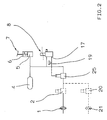
Fig.2 zeigt ausschnittsweise eine weitere Fortbildung des Ausführungsbeispiels nach Fig.1. Die Fortbildung besteht darin, daß der Bremskreis ein Relaisventil (25) enthält, welches in üblicher Weise der Zuspanneinrichtung (1) bzw. den Zuspanneinrichtungen (1, 21) vorgeschaltet ist und dessen Steuereinrichtung der von dem Bremsdruckmodulator (8) abgegebene Bremsdruck als Steuerdruck zugeführt wird.2 shows a section of a further development of the embodiment according to FIG. 1. The training consists in the fact that the brake circuit contains a relay valve (25), which is connected upstream of the application device (1) or application devices (1, 21) in a conventional manner and whose control device is supplied with the brake pressure emitted by the brake pressure modulator (8) as control pressure becomes.
Der Bremsdrucksensor (19) ist am Ausgang des Bremsdruckmodulators (8) dargestellt, kann aber auch am Ausgang des Relaisventils (25) angeordnet sein.The brake pressure sensor (19) is shown at the output of the brake pressure modulator (8), but can also be arranged at the output of the relay valve (25).
Im übrigen gelten für diese Fortbildung die zu Fig.1 gemachten Ausführungen identisch oder entsprechend.For the rest, the statements made in relation to FIG. 1 apply identically or correspondingly to this training.
Fig.3 zeigt in durchgezogenen Linien schematisch die Grundausführung einer Bremsanlage eines Anhängers.Figure 3 shows in solid lines the basic design of a braking system of a trailer.
Die mechanische Bremsdrucksteuereinrichtung (33, 34) besteht in diesem Fall aus einem Anhängerbremsventil (33) und einem lastabhängigen Bremsdruckregler (34). Beide sind von bekannten Bauarten und in üblicher Weise angeordnet. Folglich dient das Anhängerbremsventil (33) zugleich zur Fortleitung des über eine Vorratskupplung (36) vom Zugfahrzeug herangeführten Druckmittels an den Druckvorrat (4) und wird es über eine Bremskupplung (35) und eine Steuerleitung, in der auch der lastabhängige Bremsdruckregler (3) angeordnet ist, angesteuert.The mechanical brake pressure control device (33, 34) in this case consists of a trailer brake valve (33) and a load-dependent brake pressure regulator (34). Both are of known types and arranged in the usual way. Consequently, the trailer brake valve (33) also serves to transfer the pressure medium supplied from the towing vehicle via a supply coupling (36) to the pressure supply (4) and it is arranged via a brake coupling (35) and a control line in which the load-dependent brake pressure regulator (3) is also arranged is driven.
Je nach Einsatzfall kann der lastabhängige Bremsdruckregler (34) auch entfallen.Depending on the application, the load-dependent brake pressure regulator (34) can also be omitted.
Die elektrische Bremsdrucksteuereinrichtung (30, 8, 31, 19) besteht aus einem elektrischen Steueranschluß (30), der Steuerelektronik (31, 19), zu der eine Steuerschaltung (31) und ein Drucksensor (19) gehören, und einem Bremsdruckmodulator. Der wieder mit (8) bezeichnete Bremsdruckmodulator und der wieder mit (19) bezeichnete Bremsdrucksensor entsprechen prinzipiell den gleich bezeichneten Bauteilen des früheren Ausführungsbeispiels. Der Steueranschluß (30) nimmt das im Zugfahrzeug erzeugte Anhängerbremssignal auf und führt dieses der Steuerschaltung (31) zu. Der Bremsdruckmodulator (8) ist an seinem einen Eingang (3) mit dem Druckvorrat (4) und an seinem anderen Eingang (9) mit dem Ausgang des Anhängerbremsventils (33) verbunden. An seinem Ausgang (17) ist der Bremswertmodulator (8) mit der Drucksteuereinrichtung eines Relaisventils (32) verbunden, welches außerdem eine Magnetbetätigung aufweist und dadurch zugleich ein magnetgesteuertes Regelventil einer Blockierschutzanlage ist. Ein solches Regelventil, auch ABS-Relaisventil genannt, ist beispielsweise in der DE 37 30 779 A1 beschrieben.The electrical brake pressure control device (30, 8, 31, 19) consists of an electrical control connection (30), the control electronics (31, 19), to which a control circuit (31) and a pressure sensor (19) belong, and a brake pressure modulator. The brake pressure modulator, again designated by (8), and the brake pressure sensor, again designated by (19), correspond in principle to the components of the earlier exemplary embodiment that are identified by the same name. The control connection (30) receives the trailer brake signal generated in the towing vehicle and feeds it to the control circuit (31). The brake pressure modulator (8) is connected at one input (3) to the pressure supply (4) and at its other input (9) to the output of the trailer brake valve (33). At its output (17), the brake value modulator (8) is connected to the pressure control device of a relay valve (32), which also has a solenoid actuation and is thereby also a solenoid-controlled control valve of an anti-lock system. Such a control valve, also called ABS relay valve, is described for example in DE 37 30 779 A1.
Hinsichtlich der Funktionsweise dieses Ausführungsbeispiels gelten die zu dem früheren Ausführungsbeispiel in der Fortbildung nach Fig.2 gegebenen Erläuterungen identisch oder entsprechend, wobei das Anhängerbremssignal dem Betätigungssignal des elektrischen Teils (6) des Bremswertgebers (7) gleichzusetzen ist.With regard to the functioning of this exemplary embodiment, the explanations given for the previous exemplary embodiment in the further development according to FIG. 2 apply identically or correspondingly, the trailer brake signal being equivalent to the actuation signal of the electrical part (6) of the brake value transmitter (7).
Der Fachmann erkennt, daß sich dieses Ausführungsbeispiel im Bereich des ABS-Relaisventils (32) auf die Grundausführung und Fortbildungen der Fig.1 und Fig.2 rückbilden läßt und daß sich andererseits letzteres insoweit auf die Ausgestaltung dieses Ausführungsbeispiels fortbilden lassen.A person skilled in the art will recognize that this embodiment in the area of the ABS relay valve (32) can be reduced to the basic design and further developments of FIGS. 1 and 2 and that, on the other hand, the latter can be further developed to the design of this embodiment.
Fig.4 zeigt das Ausführungsbeispiel gemäß Fig.1 mit einer anderen Ausgestaltung des Bremsdruckmodulators.4 shows the exemplary embodiment according to FIG. 1 with a different embodiment of the brake pressure modulator.
Der hier generell mit (41) bezeichnete Bremsdruckmodulator besteht aus einer Zweikreis-Relaisventileinrichtung (44) und einer magnetbetätigten Ventileinrichtung (40). Die Zweikreis-Relaisventileinrichtung (44) ist von einer marktgängigen aufstockenden Bauart. Dabei bedeutet "aufstockend", daß sie bei gleichzeitiger Druckbeaufschlagung ihrer beiden Steuereinrichtungen an ihrem Ausgang einen höheren Druck als bei Druckbeaufschlagung nur einer ihrer Steuereinrichtungen abgibt.The brake pressure modulator, generally designated here with (41), consists of a two-circuit relay valve device (44) and a solenoid-operated valve device (40). The two-circuit relay valve device (44) is of a commercially available top-up type. In this context, "topping up" means that when its two control devices are pressurized at the same time, it releases a higher pressure at its outlet than when only one of its control devices is pressurized.
Die Ventileinrichtung (40) ist in bekannter Weise so ausgebildet, daß sie einen von der zugeführten Magnetstromstärke abhängigen Druck aussteuert. Als solche ist beispielsweise ein marktgängiges Magnet-Proportionalventil einsetzbar. Durch einen beide genannten Ventileinrichtungen (40) und (44) umfassenden Linienzug ist angedeutet, daß diese zur Bildung des Bremsdruckmodulators (41) zusammengebaut sind. Sie können die Funktion des Bremsdruckmodulators (41) selbstverständlich aber auch als entsprechend druckseitig miteinander verbundene Einzelgeräte erfüllen.The valve device (40) is designed in a known manner in such a way that it modulates a pressure which is dependent on the magnetic current strength supplied. As such, a commercially available magnetic proportional valve can be used, for example. A line comprising both of the aforementioned valve devices (40) and (44) indicates that these are assembled to form the brake pressure modulator (41). Of course, they can also perform the function of the brake pressure modulator (41) as individual devices that are connected to one another on the pressure side.
Der eine Eingang (3), der andere Eingang (9) und der Ausgang (17) des Bremsdruckmodulators (41) sind als Anschlußpunkte der entsprechenden Druckmittelleitungen an den erwähnten Linienzug dargestellt; bei getrennter Anordnung der Ventileinrichtung (40) und der Zweikreis-Relaisventileinrichtung (44) können die Eingänge (3) und (9) sowie der Ausgang (17) mit Anschlüssen der Ventileinrichtung (40) bzw. der Zweikreis-Relaisventileinrichtung (44) zusammenfallen.One input (3), the other input (9) and the output (17) of the brake pressure modulator (41) are shown as connection points of the corresponding pressure medium lines to the mentioned line; If the valve device (40) and the two-circuit relay valve device (44) are arranged separately, the inputs (3) and (9) and the output (17) can coincide with connections of the valve device (40) and the two-circuit relay valve device (44).
Die Ventileinrichtung (40) ist an ihrem Druckmitteleingang mit dem einen Eingang (3) verbunden. Die Zweikreis-Relaisventileinrichtung (44) ist an ihrem Vorratsanschluß ebenfalls mit dem einen Eingang (3), an ihrer einen Steuereinrichtung (42) mit dem Ausgang der Ventileinrichtung (40), an ihrer anderen Steuereinrichtung (43) mit dem zweiten Eingang (9) und an ihrem Ausgang mit dem Ausgang (17) verbunden.The valve device (40) is connected to one inlet (3) at its pressure medium inlet. The two-circuit relay valve device (44) is also connected to one input (3) at its supply connection, at one control device (42) to the outlet of the valve device (40), at its other control device (43) to the second input (9). and connected at its output to the output (17).
Der Betätigungsmagnet der Ventileinrichtung (40) stellt die Magnetbetätigung des Bremsdruckmodulators (41) dar.The actuating magnet of the valve device (40) represents the magnet actuation of the brake pressure modulator (41).
Aufgrund der Verbindungen ihrer Steuereinrichtungen (42) und (43) mit der Ventileinrichtung (40) bzw., über den anderen Eingang (9), mit der mechanischen Bremsdrucksteuereinrichtung (5) bzw. (5, 18) wird die Zweikreis-Relaisventileinrichtung (44) sowohl von dem von der Ventileinrichtung (40) ausgesteuerten Druck als auch von dem von der mechanischen Bremsdrucksteuereinrichtung (5) bzw. (5, 18) abgegebenen Druck gesteuert. Da der von der Ventileinrichtung (40) abgegebene Druck von der dem Betätigungsmagneten zugeführten Stromstarke abhängt, ist die Steuerung der Zweikreis-Relaisventileinrichtung (44) an der Steuereinrichtung (42) von dieser Magnetstromstärke abhängig.Due to the connections of their control devices (42) and (43) to the valve device (40) or, via the other input (9), to the mechanical brake pressure control device (5) or (5, 18), the two-circuit relay valve device (44 ) controlled both by the pressure controlled by the valve device (40) and by the pressure emitted by the mechanical brake pressure control device (5) or (5, 18). Since the pressure emitted by the valve device (40) depends on the current strength supplied to the actuating magnet, the control of the two-circuit relay valve device (44) on the control device (42) is dependent on this magnetic current strength.
Wegen der aufstockenden Bauart der Zweikreis-Relaisventileinrichtung (44) erbringen die Ventileinrichtung (40) und die Zweikreis-Relaisventileinrichtung (44) in Verbindung miteinander die gleichen Funktionen wie der Bremsdruckmodulator (8) des Ausführungsbeispiels gemäß Fig.1.Because of the additional construction of the two-circuit relay valve device (44), the valve device (40) and the two-circuit relay valve device (44) provide the same functions in connection with one another as the brake pressure modulator (8) of the exemplary embodiment according to FIG. 1.
In nicht näher dargestellter Weise kann der Bremsdruckmodulator (8) auch in den anderen vorstehend erwähnten Anordnungen und allgemein, gegebenenfalls mit einfachen Anpassungsmaßnahmen, durch den Bremsdruckmodulator (41) ersetzt werden.In a manner not shown, the brake pressure modulator (8) can also be used in the others mentioned above Arrangements and in general, possibly with simple adaptation measures, are replaced by the brake pressure modulator (41).
Im übrigen gelten, soweit sich aus Vorstehendem nichts anderes ergibt, die zu einem Ausführungsbeispiel gemachten Ausführungen für das andere Ausführungsbeispiel identisch oder in entsprechender Anwendung mit.Otherwise, unless otherwise stated above, the statements made for one embodiment are identical for the other embodiment or in corresponding application.
Der Fachmann erkennt, daß sich der Schutzbereich der Erfindung nicht in den beschriebenen Ausführungsbeispielen erschöpft, sondern vielmehr alle Ausgestaltungen umfaßt, deren Merkmale sich den Patentansprüchen unterordnen.Those skilled in the art will recognize that the scope of protection of the invention is not limited to the exemplary embodiments described, but rather encompasses all configurations, the features of which are subordinate to the patent claims.
Claims (12)
- Installation de freinage comportant : au moins un circuit de freinage actionné par amenée d'une pression de freinage; un dispositif mécanique de commande de pression de freinage redondante (5; 5, 18; 33, 34) et un dispositif électrique de commande de pression de freinage (6, 8, 11,19; 6, 8, 10, 11, 19; 6, 41, 11, 19; 6, 41, 10, 11, 19; 30, 8, 31, 19; 30, 8, 10, 31, 19) auquel appartiennent au moins un modulateur de pression de freinage (8; 41) conjugué au circuit de freinage et actionné magnétiquement; et une électronique de commande (11, 19; 31, 19) commandant le modulateur de pression de freinage (8; 41); le modulateur de pression de freinage (8; 41) ayant une première entrée (3) reliée à une réserve de pression (4), une autre entrée (9) reliée au dispositif mécanique de commande de pression de freinage (5; 5, 18; 33, 34), et sa sortie (17) délivrant la pression de freinage étant reliée au circuit de freinage,
caractérisée
par le fait que le modulateur de pression de freinage (8; 41) est d'un type également commandé par pression, qui dose la pression de freinage aussi bien en fonction du courant magnétisant appliqué qu'en fonction du niveau de la pression de freinage redondante, et par le fait que l'électronique de commande (11, 19; 31, 19) est réalisée de manière à régler l'intensité du courant magnétisant à une valeur nécessaire pour couvrir la demande de pression de freinage dans chaque cas. - Installation de freinage selon revendication 1, caractérisée par le fait que l'électronique de commande (11, 19; 31, 19) délivre un signal d'avertissement si l'intensité du courant magnétisant sort du domaine de consigne prédéterminé.
- Installation de freinage selon l'une des revendications 1 ou 2, caractérisée par le fait que le modulateur de pression de freinage (41) est constitué par un dispositif de vanne-relais à deux circuits (44) et par un dispositif de vanne (40) actionné magnétiquement, délivrant une pression dépendant de l'intensité du courant magnétisant amené et ayant son entrée reliée à ladite première entrée (3), le dispositif de vanne-relais (44) ayant son premier dispositif de commande (42)relié à la sortie du dispositif de vanne actionné magnétiquement (40), son autre dispositif de commande (43) relié à l'autre entrée (9), sa sortie reliée à la sortie (17), et en son raccord de réserve relié à la première entrée (3).
- Installation de freinage selon l'une des revendications précédentes, caractérisée par le fait que le dispositif de commande mécanique de pression de freinage (5, 18) présente un dispositif de retenue qui retient la pression de freinage redondante jusqu'à une pression de retenue prédéterminée.
- Installation de freinage selon la revendication 4, caractérisée par le fait que la pression de retenue est une fonction de la pression de freinage délivrée par le modulateur de pression de freinage (8; 41).
- Installation de freinage selon l'une de revendications 4 ou 5, dans laquelle le dispositif de commande électrique de pression de freinage (6, 8, 10, 11, 19) comporte un régulateur de pression de freinage en fonction de la charge, caractérisée par le fait que la pression de retenue est au plus égale à la pression de freinage que le modulateur de pression de freinage (8; 41) délivre lorsque le véhicule est vide.
- Installation de freinage selon l'une des revendications 4 ou 6, caractérisée par le fait que le dispositif de retenue (18) est une vanne ou soupape de décharge.
- Installation de freinage selon l'une des revendications 4 à 6, caractérisée par le fait que le dispositif de retenue (18) est une vanne charge/vide.
- Installation de freinage selon l'une des revendications précédentes, caractérisée par le fait qu'au moins dans le domaine de freinage partiel, la demande de pression de freinage est plus grande que la pression de freinage redondante.
- Installation de freinage selon l'une des revendications précédentes, caractérisée par le fait que le circuit de freinage contient au moins une vanne-relais (25; 32) au dispositif de commande de laquelle est amenée, en tant que pression de commande, la pression de freinage délivrée par le modulateur de pression de freinage (8; 41).
- Installation de freinage selon revendication 10, caractérisée par le fait que la vanne-relais (32) est en même temps une vanne de réglage, commandée magnétiquement, d'une installation antiblocage (4).
- Installation de freinage selon l'une des revendications précédentes, avec une vanne de commande de remorque (16) commandée par pression, caractérisée par le fait qu'il est prévu un modulateur de pression supplémentaire (8; 41) du type spécifié dans la revendication 1, et par le fait qu'un dispositif de commande de pression de la vanne de commande de remorque (16) est relié à la sortie (17) du modulateur de pression de freinage supplémentaire (8; 41).
Applications Claiming Priority (4)
| Application Number | Priority Date | Filing Date | Title |
|---|---|---|---|
| DE4008601 | 1990-03-17 | ||
| DE4008601 | 1990-03-17 | ||
| DE4016463 | 1990-05-22 | ||
| DE4016463A DE4016463A1 (en) | 1990-03-17 | 1990-05-22 | BRAKE SYSTEM WITH AT LEAST ONE BRAKE CIRCUIT |
Publications (2)
| Publication Number | Publication Date |
|---|---|
| EP0447750A1 EP0447750A1 (en) | 1991-09-25 |
| EP0447750B1 true EP0447750B1 (en) | 1993-09-01 |
Family
ID=25891242
Family Applications (1)
| Application Number | Title | Priority Date | Filing Date |
|---|---|---|---|
| EP91100622A Expired - Lifetime EP0447750B1 (en) | 1990-03-17 | 1991-01-19 | Brake system with at least one brake circuit |
Country Status (6)
| Country | Link |
|---|---|
| US (1) | US5294190A (en) |
| EP (1) | EP0447750B1 (en) |
| JP (1) | JP2757270B2 (en) |
| DE (2) | DE4016463A1 (en) |
| ES (1) | ES2044622T3 (en) |
| PL (1) | PL164912B1 (en) |
Cited By (3)
| Publication number | Priority date | Publication date | Assignee | Title |
|---|---|---|---|---|
| FR2698332A1 (en) * | 1992-11-26 | 1994-05-27 | Renault | Braking control method for road vehicle - applying control signals using pressure sensors, and detection of sliding of wheel to determine adjustment required to create optimum braking pressure |
| EP1000830A2 (en) | 1998-11-13 | 2000-05-17 | WABCO GmbH | Brake control adjuster with integrated adding redundancy |
| DE10042215C5 (en) * | 2000-08-28 | 2005-09-01 | Knorr-Bremse Systeme für Nutzfahrzeuge GmbH | Pressure-medium-operated vehicle brake system with redundant control of at least one brake cylinder |
Families Citing this family (27)
| Publication number | Priority date | Publication date | Assignee | Title |
|---|---|---|---|---|
| EP0586203B1 (en) * | 1992-09-03 | 1997-01-02 | Grau Limited | Braking systems |
| DE4232492C2 (en) * | 1992-09-28 | 1995-03-30 | Grau Gmbh | Service brake valve for an electrically or pneumatically actuated brake system of a motor vehicle |
| DE4242887A1 (en) * | 1992-12-18 | 1994-06-23 | Wabco Westinghouse Fahrzeug | Brake system with at least one brake |
| FR2701531B1 (en) † | 1993-02-12 | 1995-04-28 | Alliedsignal Europ Services | Proportional pneumatic solenoid valve. |
| US5370449A (en) * | 1993-10-12 | 1994-12-06 | Eaton Corporation | Electrically operated parking brake system |
| WO1995016594A1 (en) * | 1993-12-17 | 1995-06-22 | Knorr-Bremse Systeme für Nutzfahrzeuge GmbH | Electropneumatic brake system for motor vehicles |
| WO1997038886A1 (en) * | 1996-04-17 | 1997-10-23 | Lucas Industries Public Limited Company | Improvements in vehicle hydraulic braking systems of the brake-by-wire type |
| US5758929A (en) * | 1996-09-11 | 1998-06-02 | New York Air Brake Corporation | Variable capacity electropneumatic control valve |
| DE19755431A1 (en) * | 1997-12-13 | 1999-06-17 | Wabco Gmbh | Vehicle brake system |
| US6179390B1 (en) * | 1998-04-24 | 2001-01-30 | Saturn Electronics & Engineering, Inc. | Electronic trailer brake controller |
| SE516430C2 (en) * | 2000-05-05 | 2002-01-15 | Volvo Articulated Haulers Ab | Device and method for activating an emergency brake function of a vehicle |
| US6994381B1 (en) | 2000-07-20 | 2006-02-07 | Contech Construction Products Inc. | Stab joint coupling |
| DE10053607A1 (en) * | 2000-10-28 | 2002-05-02 | Bosch Gmbh Robert | Arrangement for determining temperature of valves in vehicle brake circuits determines valve coil temperature from temperature dependency of coil resistance derived from wheel forces |
| US6527348B2 (en) * | 2001-05-22 | 2003-03-04 | Caterpillar Inc | Braking system for a construction machine |
| US6485111B2 (en) | 2000-12-22 | 2002-11-26 | Visteon Global Technologies, Inc. | Power assisted braking system |
| US6626506B2 (en) * | 2001-04-23 | 2003-09-30 | Westinghouse Air Brake Technologies Corporation | Method and apparatus for controlling electro-pneumatic braking on a train |
| DE10133440C2 (en) * | 2001-07-10 | 2003-06-18 | Knorr Bremse Systeme | Brake system with electro-pneumatic modulator |
| DE10156673A1 (en) * | 2001-11-17 | 2003-05-28 | Wabco Gmbh & Co Ohg | Method for operating an electrically controlled pressure brake system |
| DE10158065B4 (en) * | 2001-11-27 | 2010-09-23 | Wabco Gmbh | Redundancy pressure changeover valve for electronic-pneumatic brake system |
| US20040130207A1 (en) * | 2003-01-07 | 2004-07-08 | Westinghouse Air Brake Technologies | Three state magnet valve |
| DE102012003106C5 (en) * | 2012-02-16 | 2022-01-27 | Knorr-Bremse Systeme für Nutzfahrzeuge GmbH | Method for determining a brake pressure value using characteristic curves |
| US8783791B2 (en) | 2012-05-30 | 2014-07-22 | Bendix Commercial Vehicle Systems Llc | Dual circuit pneumatic foot valve with electronically controlled proportional modulator (ECPM) and operator input sensing |
| DE102016004489A1 (en) | 2016-04-18 | 2017-10-19 | Wabco Gmbh | Driver brake valve, compressed air brake system with the driver's brake valve and method of making the driver's brake valve |
| GB201722251D0 (en) * | 2017-12-29 | 2018-02-14 | Agco Int Gmbh | Load-dependent trailer brake system and method of controlling such |
| EP3626558B1 (en) | 2018-09-18 | 2022-10-26 | KNORR-BREMSE Systeme für Nutzfahrzeuge GmbH | Brake system for a vehicle |
| US11511716B2 (en) | 2019-06-12 | 2022-11-29 | Bendix Commercial Vehicle Systems Llc | EBS tractor control line to trailer system to improve transmission timing for an air brake system |
| DE102021112831A1 (en) * | 2021-05-18 | 2022-11-24 | Zf Cv Systems Global Gmbh | Electropneumatic assembly with integrated failsafe valve arrangement for multiple errors, electronically controllable pneumatic brake system, and method for operating a brake system |
Family Cites Families (14)
| Publication number | Priority date | Publication date | Assignee | Title |
|---|---|---|---|---|
| FR2133591B1 (en) * | 1971-04-16 | 1977-06-17 | Bendix Corp | |
| DE2939907A1 (en) * | 1979-10-02 | 1981-05-07 | Wabco Fahrzeugbremsen Gmbh, 3000 Hannover | Twin circuit brake control valve - has stepped piston for direct control of front brakes |
| DE3205228C2 (en) * | 1982-02-13 | 1999-04-01 | Bosch Gmbh Robert | Multi-circuit pressure medium brake system |
| DE3207793A1 (en) * | 1982-03-04 | 1983-09-08 | Robert Bosch Gmbh, 7000 Stuttgart | TROLLEW BRAKE SYSTEM |
| DE3212930A1 (en) * | 1982-04-07 | 1983-10-13 | Robert Bosch Gmbh, 7000 Stuttgart | Multiple circuit brake system II |
| DE3215475A1 (en) * | 1982-04-24 | 1983-11-03 | Robert Bosch Gmbh, 7000 Stuttgart | ELECTRO-PNEUMATIC BRAKE SYSTEM |
| DE3219140C2 (en) * | 1982-05-21 | 1995-03-16 | Bosch Gmbh Robert | Wagon train braking system |
| DE3230971A1 (en) * | 1982-08-20 | 1984-04-12 | Robert Bosch Gmbh, 7000 Stuttgart | MULTI-CIRCLE BRAKE SYSTEM |
| DE3239970A1 (en) * | 1982-10-28 | 1984-07-12 | Robert Bosch Gmbh, 7000 Stuttgart | CAR TRAIN BRAKE SYSTEM |
| DE3240276A1 (en) * | 1982-10-30 | 1984-05-03 | Robert Bosch Gmbh, 7000 Stuttgart | Pressure-control valve for a brake system |
| DE3416338A1 (en) * | 1984-05-03 | 1985-11-07 | Wabco Westinghouse Fahrzeugbremsen GmbH, 3000 Hannover | Device for adjusting the brake force distribution |
| DE3501179A1 (en) * | 1985-01-16 | 1986-07-17 | Wabco Westinghouse Fahrzeugbremsen GmbH, 3000 Hannover | ELECTRIC BRAKE SYSTEM |
| DE3603143A1 (en) * | 1986-02-01 | 1987-08-06 | Bosch Gmbh Robert | Electro-pneumatic brake system |
| DE3703639A1 (en) * | 1987-02-06 | 1988-08-18 | Bosch Gmbh Robert | ELECTRO-PNEUMATIC BRAKE SYSTEM FOR TRAIN VEHICLES |
-
1990
- 1990-05-22 DE DE4016463A patent/DE4016463A1/en not_active Withdrawn
-
1991
- 1991-01-19 DE DE91100622T patent/DE59100334D1/en not_active Expired - Lifetime
- 1991-01-19 ES ES91100622T patent/ES2044622T3/en not_active Expired - Lifetime
- 1991-01-19 EP EP91100622A patent/EP0447750B1/en not_active Expired - Lifetime
- 1991-03-05 US US07/664,880 patent/US5294190A/en not_active Expired - Lifetime
- 1991-03-07 JP JP3123291A patent/JP2757270B2/en not_active Expired - Lifetime
- 1991-03-11 PL PL91289379A patent/PL164912B1/en not_active IP Right Cessation
Cited By (4)
| Publication number | Priority date | Publication date | Assignee | Title |
|---|---|---|---|---|
| FR2698332A1 (en) * | 1992-11-26 | 1994-05-27 | Renault | Braking control method for road vehicle - applying control signals using pressure sensors, and detection of sliding of wheel to determine adjustment required to create optimum braking pressure |
| EP1000830A2 (en) | 1998-11-13 | 2000-05-17 | WABCO GmbH | Brake control adjuster with integrated adding redundancy |
| US6354671B1 (en) | 1998-11-13 | 2002-03-12 | Wabco Gmbh | Brake signal transmitter with integrated addition redundancy |
| DE10042215C5 (en) * | 2000-08-28 | 2005-09-01 | Knorr-Bremse Systeme für Nutzfahrzeuge GmbH | Pressure-medium-operated vehicle brake system with redundant control of at least one brake cylinder |
Also Published As
| Publication number | Publication date |
|---|---|
| JP2757270B2 (en) | 1998-05-25 |
| PL289379A1 (en) | 1991-11-04 |
| DE59100334D1 (en) | 1993-10-07 |
| US5294190A (en) | 1994-03-15 |
| JPH04228347A (en) | 1992-08-18 |
| DE4016463A1 (en) | 1991-09-19 |
| PL164912B1 (en) | 1994-10-31 |
| ES2044622T3 (en) | 1994-01-01 |
| EP0447750A1 (en) | 1991-09-25 |
Similar Documents
| Publication | Publication Date | Title |
|---|---|---|
| EP0447750B1 (en) | Brake system with at least one brake circuit | |
| EP1464557B1 (en) | Compressed air treament device | |
| DE69410508T2 (en) | Electro-hydraulic brake device for the landing gear of an aircraft | |
| DE4340467C2 (en) | Hydraulic vehicle brake system working with external power | |
| DE3789194T2 (en) | Control device for vehicle brake pressure. | |
| EP0307579B1 (en) | Magnetically controlled valve installation | |
| DE3102227C2 (en) | ||
| DE3124755A1 (en) | VEHICLE BRAKE SYSTEM | |
| EP0813481B1 (en) | Braking pressure regulator | |
| DE69121707T2 (en) | VALVE FOR AUTOMATIC BRAKE SYSTEM | |
| EP0733532A2 (en) | Method for determining set pressure of a pressure-actuated brake in a vehicle brake system | |
| DE3410083A1 (en) | Pressure-actuated brake system for motor vehicles | |
| DE3423944A1 (en) | Vehicle brake system | |
| DE69104476T2 (en) | ELECTROHYDRAULIC OR ELECTROPNEUMATIC BRAKE CONTROL DEVICE FOR TRAILER AXLES WITH AUXILIARY BRAKES. | |
| EP0733531B1 (en) | Method for braking a vehicle | |
| DE3818617C2 (en) | ||
| DE3312981C2 (en) | ||
| EP0530460B1 (en) | Trailer brake system | |
| DE102008009948B3 (en) | Brake system for commercial vehicles | |
| EP0569697B1 (en) | Method for surveillance of overload of a trailer brake of a tractor-trailer combination | |
| DE2737938A1 (en) | HYDRAULIC ANTI-LOCKING DEVICE | |
| DE3545021A1 (en) | Electro-pneumatic brake system | |
| DE4004502C2 (en) | ||
| EP0569698B1 (en) | Mehtod for surveillance of overload of a tractor brake of a tractor-trailer combination | |
| EP1312524B1 (en) | Method of operating an electrically controlled braking system |
Legal Events
| Date | Code | Title | Description |
|---|---|---|---|
| PUAI | Public reference made under article 153(3) epc to a published international application that has entered the european phase |
Free format text: ORIGINAL CODE: 0009012 |
|
| 17P | Request for examination filed |
Effective date: 19910708 |
|
| AK | Designated contracting states |
Kind code of ref document: A1 Designated state(s): DE ES FR GB IT NL SE |
|
| 17Q | First examination report despatched |
Effective date: 19921217 |
|
| RAP1 | Party data changed (applicant data changed or rights of an application transferred) |
Owner name: WABCO VERMOEGENSVERWALTUNGS-GMBH |
|
| GRAA | (expected) grant |
Free format text: ORIGINAL CODE: 0009210 |
|
| AK | Designated contracting states |
Kind code of ref document: B1 Designated state(s): DE ES FR GB IT NL SE |
|
| REF | Corresponds to: |
Ref document number: 59100334 Country of ref document: DE Date of ref document: 19931007 |
|
| ITF | It: translation for a ep patent filed | ||
| ET | Fr: translation filed | ||
| REG | Reference to a national code |
Ref country code: ES Ref legal event code: FG2A Ref document number: 2044622 Country of ref document: ES Kind code of ref document: T3 |
|
| GBT | Gb: translation of ep patent filed (gb section 77(6)(a)/1977) |
Effective date: 19931215 |
|
| PLBE | No opposition filed within time limit |
Free format text: ORIGINAL CODE: 0009261 |
|
| STAA | Information on the status of an ep patent application or granted ep patent |
Free format text: STATUS: NO OPPOSITION FILED WITHIN TIME LIMIT |
|
| 26N | No opposition filed | ||
| EAL | Se: european patent in force in sweden |
Ref document number: 91100622.9 |
|
| REG | Reference to a national code |
Ref country code: GB Ref legal event code: IF02 |
|
| PGFP | Annual fee paid to national office [announced via postgrant information from national office to epo] |
Ref country code: GB Payment date: 20070117 Year of fee payment: 17 |
|
| PGFP | Annual fee paid to national office [announced via postgrant information from national office to epo] |
Ref country code: ES Payment date: 20070125 Year of fee payment: 17 |
|
| GBPC | Gb: european patent ceased through non-payment of renewal fee |
Effective date: 20080119 |
|
| PG25 | Lapsed in a contracting state [announced via postgrant information from national office to epo] |
Ref country code: GB Free format text: LAPSE BECAUSE OF NON-PAYMENT OF DUE FEES Effective date: 20080119 |
|
| REG | Reference to a national code |
Ref country code: ES Ref legal event code: FD2A Effective date: 20080121 |
|
| PG25 | Lapsed in a contracting state [announced via postgrant information from national office to epo] |
Ref country code: ES Free format text: LAPSE BECAUSE OF NON-PAYMENT OF DUE FEES Effective date: 20080121 |
|
| PGFP | Annual fee paid to national office [announced via postgrant information from national office to epo] |
Ref country code: SE Payment date: 20091221 Year of fee payment: 20 |
|
| PGFP | Annual fee paid to national office [announced via postgrant information from national office to epo] |
Ref country code: IT Payment date: 20100130 Year of fee payment: 20 Ref country code: FR Payment date: 20100211 Year of fee payment: 20 |
|
| PGFP | Annual fee paid to national office [announced via postgrant information from national office to epo] |
Ref country code: DE Payment date: 20100131 Year of fee payment: 20 |
|
| PGFP | Annual fee paid to national office [announced via postgrant information from national office to epo] |
Ref country code: NL Payment date: 20100118 Year of fee payment: 20 |
|
| REG | Reference to a national code |
Ref country code: NL Ref legal event code: V4 Effective date: 20110119 |
|
| PG25 | Lapsed in a contracting state [announced via postgrant information from national office to epo] |
Ref country code: NL Free format text: LAPSE BECAUSE OF EXPIRATION OF PROTECTION Effective date: 20110119 |
|
| PG25 | Lapsed in a contracting state [announced via postgrant information from national office to epo] |
Ref country code: DE Free format text: LAPSE BECAUSE OF EXPIRATION OF PROTECTION Effective date: 20110119 |