EP0447749A2 - Méthode de transmission de données à débit multiple - Google Patents
Méthode de transmission de données à débit multiple Download PDFInfo
- Publication number
- EP0447749A2 EP0447749A2 EP91100428A EP91100428A EP0447749A2 EP 0447749 A2 EP0447749 A2 EP 0447749A2 EP 91100428 A EP91100428 A EP 91100428A EP 91100428 A EP91100428 A EP 91100428A EP 0447749 A2 EP0447749 A2 EP 0447749A2
- Authority
- EP
- European Patent Office
- Prior art keywords
- burst
- data
- time
- control
- subscriber
- Prior art date
- Legal status (The legal status is an assumption and is not a legal conclusion. Google has not performed a legal analysis and makes no representation as to the accuracy of the status listed.)
- Withdrawn
Links
Images


Classifications
-
- H—ELECTRICITY
- H04—ELECTRIC COMMUNICATION TECHNIQUE
- H04J—MULTIPLEX COMMUNICATION
- H04J3/00—Time-division multiplex systems
- H04J3/22—Time-division multiplex systems in which the sources have different rates or codes
-
- H—ELECTRICITY
- H04—ELECTRIC COMMUNICATION TECHNIQUE
- H04J—MULTIPLEX COMMUNICATION
- H04J3/00—Time-division multiplex systems
- H04J3/02—Details
- H04J3/06—Synchronising arrangements
- H04J3/0635—Clock or time synchronisation in a network
- H04J3/0682—Clock or time synchronisation in a network by delay compensation, e.g. by compensation of propagation delay or variations thereof, by ranging
-
- H—ELECTRICITY
- H04—ELECTRIC COMMUNICATION TECHNIQUE
- H04J—MULTIPLEX COMMUNICATION
- H04J3/00—Time-division multiplex systems
- H04J3/16—Time-division multiplex systems in which the time allocation to individual channels within a transmission cycle is variable, e.g. to accommodate varying complexity of signals, to vary number of channels transmitted
- H04J3/1605—Fixed allocated frame structures
Definitions
- the invention relates to a method for transmitting data at different rates according to the preamble of claim 1.
- Time division multiplexing is known.
- these are synchronous transmission methods, i.e. Data is transmitted at a constant bit rate, and there is a frame that is divided into different time intervals. Information is packed into each time interval, for example for a subscriber, so that multiple use of the transmission line is achieved.
- passwords are sent, for example, at the beginning of a frame, which identify the beginning thereof.
- the object of the invention is to develop a time-division multiplex frame which makes it possible to synchronize data at different rates in one time frame. This object is achieved according to the invention by the features mentioned in the characterizing part of claim 1. Further developments of the invention are contained in the subclaims.
- the invention is used for example in local area networks with optical transmission. If you want to allow variable data rates in the individual time intervals of a time frame, the individual participants T 1, T 2 ... T n must first be informed of where the beginning of the frame is. This relates to the reception of a data stream which reaches the individual subscribers via a common line, ie the main cable HK (see FIG. 1), the cable distributor KVZ and the subscriber-side multiplex device or subscriber group connection unit TGAE. In the opposite direction, the TGAE assigns one of the free time intervals to the sending subscriber and sends the information to the central multiplex device ZAE. This is part of a private or public network.
- the difficulty is that different frequencies, ie data rates are offered or used by the participants and you in principle need a common data rate to tell all participants T1, T2 ... T n where the beginning of the frame is.
- a second solution would be to send a frame identifier which is based on an analog method in which the receiver is not forced to understand a common data rate.
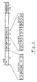
- a time frame is shown in which a common data rate for all receivers or participants T1, T2 ... T n is used to mark the beginning of a frame to identify.
- you divide the transmission frame into 33 time intervals ZI, for example, which are assigned to a reference burst ZI0 and 32 subscribers ZI1-ZI32 you can send a control burst SB1 .... SB32 in every time interval, i.e. a packet or pulse train ( Burst) with a fixed rate that is understandable for each participant and use the remaining part of the time interval for a data burst DB with a variable data rate D. Only the time interval ZI2 is drawn here; ZI1 ... ZI32 are also constructed.
- control burst SB With the fixed rate, in order to enable the receiver to switch to the selected variable frequency in good time (via frequency information).
- this control burst SB can also carry the target address ZA for the following burst and thus inform the receiver circuit that a time interval is now available. This is particularly important so that a recipient who can show or hide the information that is intended for him or for other participants with a time mask. It is conceivable that the different data rates in the time intervals could otherwise lead to interference.
- the receiver examines the data stream, looks at the control bursts SB of all participants and evaluates them, and then uses the address to decide whether a control burst has been sent to them. All control bursts of a frame, which it has registered as being sent for itself, are switched through together with the associated data bursts in the receiver; all others are blocked early in the preamplifiers of the receiver, so that interference cannot occur. To control this time mask, the length of the burst is also made variable Transfer data rate so that you can control the mask very precisely in time.
- the frame structure of a preferred embodiment of the invention is described in detail below.
- the frame ( Figure 2) consists of 33 time intervals that are transmitted in turn.
- the reference burst RB is located in the time interval 0. This has the task of marking the beginning of a frame and also serves to measure the distance between the control center and the subscriber.
- Control and data bursts are sent in the remaining 32 time intervals ZI1 ... ZI32. There are protection times S between the individual time intervals. Control and data bursts are also separated from one another by protection times within the time intervals.
- the reference and control bursts have a fixed data rate that can be understood by all receivers in the central office and at the subscriber.
- the control burst consists of PR: preamble, SW: start word, TY: type, BE: assignment, ZA: destination address, D: data rate, DA: data and PS: checksum.
- the preamble provides the receiver in the central office or at the subscriber with the necessary clock information in order to establish bit synchronism for the control burst.
- the start word marks the beginning of the relevant information.
- the type field TY contains information as to whether the user data are transmitted in a separate data burst DB or in the data field DA of the control burst in the corresponding time interval. When transmitting in the control burst SB, this fills the entire time interval.
- the occupancy field BE indicates whether user data are transmitted in the data field or not.
- the destination address ZA is used to address a subscriber.
- the data rate field D passes the information to the recipient at the central office or at the subscriber which data rate the data burst DB is transmitted in the same time interval.
- the receiver can be programmed to the respective data rate or that it can process a large range of data rates. Since there are optical receivers that can process data rates between 1 Mbit / s and 50 Mbit / s, for example, by programming the clock recovery circuit to one of approx. 50 available frequency bands, it is sufficient in this case if you have an identifier for the sends the relevant frequency band to be transmitted data rate.
- the checksum PS is formed on the transmission side via all bits between the start of the type field and the end of the data field and is also transmitted. This means that the recipient can track down transmission errors.
- the data burst consists of PR: preamble, SW: start word, DA: data and PS: checksum. Since the occupancy, destination address and data rate of the data burst are already transmitted in the control burst, this information can be omitted in the data burst.
- the data burst has its own preamble PR, which is also used for bit synchronization. This is followed by the start word SW, which marks the start of the user data.
- the user data are packed into the data field DA and the checksum calculated using this user data is transmitted in the following checksum field PS.
- the reference burst consists of PR: preamble, SW: start word, RKW: frame identification word, ZA: destination address, EMW, distance measurement word, ELZ: echo runtime and PS: checksum.
- the reference burst also begins with the preamble and start word.
- the frame identifier marks the beginning of a new frame.
- the subsequent destination address ZA addresses the subscriber who is to carry out a distance measurement in the current frame by sending the received reference burst back to the central connection unit ZAE immediately after recognizing the frame identification word, its own address and the distance measurement word EMW.
- the echo delay time ELZ is the time reserved within the frame that the subscriber needs to send the echo back over the fiber optic cable.
- the checksum PS is formed over all bits of the target address, the distance measurement word and the echo delay.
- the data burst with the variable data rate can therefore also be eliminated in one time interval (or in several time intervals), so that only the control burst still exists.
- the control burst SB also contains the data part with the user data.
- the information about the address, length and frequency before the data part relates to the burst itself.
- the frequency specification is of no interest, since all receivers can process the fixed frequency or data rate.
- the advantage of this measure is that there can also be very inexpensive receivers that can only receive at this fixed data rate and still work in the mixed system.
- a reference burst RB is first sent, which makes the run times measurable for the individual participants.
- the reference burst has an internal identifier.
- the control center can measure the duration of the burst up to the subscriber and back, how long the transit time to to the participant. From this it can be deduced how much delay the subscriber has to send in the reverse direction in order to send without collision. This allows the gap to be reduced to a few bit positions, for example, so that a better yield in the data rate is obtained.
- a preferred exemplary embodiment of the invention for the subscriber group interface unit TGAE is described below with reference to the block diagram of FIG. 3.
- the time-division multiplex signals are obtained via an optical fiber line in the optical receiver OE.
- the subscriber group interface unit TGAE in FIG. 3 receives from the central interface unit ZAE, which will be described below, a time-division multiplex frame which carries different data rates D in the individual time intervals (see FIG. 2).
- the optical receiver OE works in broadband and can do it all - or those for the services required at the subscriber - process data rates.
- the signal detector SD reports to the masking control MS when a valid burst is present at the output of the optical receiver.
- the masking control MS can uniquely recognize the reference burst RB by its length and can generate a time mask therefrom which initially switches the optical receiver OE transparent only for the reference and control bursts.
- the clock recovery TG is first programmed to the fixed data rate of the reference and control bursts. These bursts are regenerated in time in the data regenerator DR and decoded in the channel decoder KD.
- the demultiplexer DM routes the reference and control bursts to the respective burst receivers. These separate the useful information from the preamble and start word, calculate the checksums and compare them with the transmitted checksums.
- the reference burst receiver RE also evaluates the frame code word RKW and compares the received destination address with its own TGAE address. If the addresses match, the distance measurement word EMW is forwarded to the EMW detector. If it receives a correct EMW, it gives the reference burst generator the command to generate a reference burst. At the same time, a loop is switched that sends the reference burst generated in this way back to the ZAE.
- the control burst receiver SE evaluates the destination address ZA in the control burst. If this corresponds to the own TGAE address, the information in the type field decides whether a data burst with user data follows or the user data is in the data field of the control burst. If an occupied data burst follows the control burst, the data rate is communicated to the data burst receiver DE and the data rate controller DS. At the end of the control burst, the clock recovery circuit TG and the data burst receiver DE is automatically reprogrammed to the new data rate. The reprogramming must take place during the protection time S between the control and data burst. At the end of the data burst, the old data rate is reprogrammed, etc.
- the control burst receiver SE also makes the optical receiver OE transparent to the duration of the data burst via the masking control MS when it is addressed to its own TGAE.
- Runtime compensation is an electronic memory with programmable depth and lead time.
- the decompression memories D1 and D2 receive the time-compressed data packets from the data or control burst receivers and convert them into continuous-time data streams.
- the adaptation unit AE (“Line Interface Unit") adapts the user and control data to the subscriber terminal.
- the subscriber terminal passes on continuous time useful and control data via the adaptation unit AE to the compression memories K1 and K2.
- the compression memories collect the continuous useful and control data intended for a packet and send them to the corresponding burst generators in a time-compressed manner. These pack the user data together with the preamble, the start word and the checksum into the intended package structure.
- the burst generators generate the control, data and reference bursts, which are combined in the multiplexer MX to form a data stream.
- the runtime compensation LA shifts the transmission time of this data stream so that the data streams of all TGAEs in the star point in front of the ZAE change to a collision-free time Assemble time-division multiplex frames.
- clock information is added to the data stream via the line coding.
- the optical transmitter OS converts the electrical line-coded data signal into an optical data signal, which is sent to the ZAE.
- the optical fibers in the associated cable distributor KVZ are interconnected with the help of star couplers to one bus each for the direction of the switching subscriber and vice versa.
- the two star couplers are connected with a pair of fibers to a central interface unit ZAE in the exchange.
- a repeater with amplitude regeneration is also provided in the KVZ.
- the principle of the system is that data blocks are transmitted regularly between the ZAE and the subscriber group interface units TGAE, which enable permanent communication between all end users and the exchange.
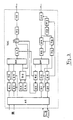
- the central interface unit ZAE (see Fig. 4) has a very similar structure.
- the optical receiver OE is a broadband receiver that can process different data rates D.
- the data rate comes from the optical receiver to the data regenerator DR. This has the task of regenerating the data in time together with the clock recovery circuit TG.
- the clock recovery is a programmable unit which is programmed to a data rate D via the "data rate" control and can then perform a regeneration for this data rate together with the data regenerator DR.
- the signal detector SD decides when incoming data is available and communicates this to the masking control MS. This can then only be the bursts with fixed Let the data rate through so that the receiver can first check what is being sent in the data bursts that follow the control bursts, or at what data rate is being sent there.
- the process is as follows: first, for example, there is a control burst with a fixed data rate, the clock recovery is then programmed to this fixed data rate. The data rate at which the subsequent data burst is sent is transferred in this control burst, and as soon as the control burst has ended, the clock recovery is immediately reprogrammed to this new data rate indication, so that subsequently the data rate contained in the data burst is received can be. It is important here that in the ZAE the clock recovery circuit is continuously reprogrammed in a data frame, so that when a reference burst or a control burst is received which are sent at a fixed data rate, the clock recovery is programmed to this fixed data rate. When changing to a data burst, the existing data rate is reprogrammed. For the clock recovery circuit, this means that it can be completely reprogrammed within the protection times. The protection time should be chosen accordingly.
- the main difference between the TGAE and the ZAE is that the ZAE generates a reference burst with the associated address and sends it to the TGAE.
- the addressed TGAE then closes a loop switch SL and sends the echo of this reference burst back to the ZAE.
- the ZAE receives this echo in its optical reception branch and measures the transit time between the transmission of the reference burst and the returning echo.
- the control computer SR evaluates the measured runtime and outputs certain bits of the distance measurement word forward the information to the TGAE, which it needs to adjust the runtime compensation according to the measurement value.
- This means that all TGAEs connected to a ZAE can set their round trip time, ie the running time between ZAE, TGAE and back to the ZAE to a uniform value. This means that the message transmission between the ZAE and any TGAE is always standardized to a fixed runtime.
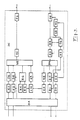
- the ZAE in FIG. 5 there are separate receiver circuits after the optical receiver and preamplifier OE 2.
- the upper branch understands the fixed data rate that is always present in the reference burst and in the control burst.
- the lower branch processes the changing data rate of the data burst, which can have a different data rate coming from a subscriber.
- the reprogramming of the clock recovery circuit in the lower data branch is now to be carried out in longer periods, as soon as e.g. Data burst 1 has been completely transmitted, the reprogramming for the reception of the data burst 2 can take place in the period of the control burst and in the subsequent protection time. This time is longer than the time between the control burst and the subsequent data burst, which is present in the ZAE as the reprogramming time.
- a time masking MS is necessary, which is carried out by a signal detector SD is controlled.
- the signal detector SD reports when data is available and when there is no data. Since the reference burst represents the longest data transmission in a block in time, the position of the reference burst in time can in principle also be determined directly with the signal detector SD.
- a mask is then controlled in such a way that only the reference burst and, for example, all control bursts are initially passed through. This is only important for the electronics participants.
- the addresses are checked in the control burst and then a decision is made: this is your own address, ie the information relevant to the subscriber is available.
- this is your own address, ie the information relevant to the subscriber is available.
- the bursts with the mask that must be processed for the respective subscriber are then released.
Applications Claiming Priority (2)
| Application Number | Priority Date | Filing Date | Title |
|---|---|---|---|
| DE19904008727 DE4008727A1 (de) | 1990-03-19 | 1990-03-19 | Verfahren zum uebertragen von daten unterschiedlicher rate |
| DE4008727 | 1990-03-19 |
Publications (2)
| Publication Number | Publication Date |
|---|---|
| EP0447749A2 true EP0447749A2 (fr) | 1991-09-25 |
| EP0447749A3 EP0447749A3 (en) | 1993-04-14 |
Family
ID=6402525
Family Applications (1)
| Application Number | Title | Priority Date | Filing Date |
|---|---|---|---|
| EP19910100428 Withdrawn EP0447749A3 (en) | 1990-03-19 | 1991-01-16 | Method for transmitting multirate data |
Country Status (2)
| Country | Link |
|---|---|
| EP (1) | EP0447749A3 (fr) |
| DE (1) | DE4008727A1 (fr) |
Cited By (1)
| Publication number | Priority date | Publication date | Assignee | Title |
|---|---|---|---|---|
| FR2737826A1 (fr) * | 1995-08-08 | 1997-02-14 | Sextant Avionique | Procede de communication sur un bus a cohabitation de debits differents |
Families Citing this family (1)
| Publication number | Priority date | Publication date | Assignee | Title |
|---|---|---|---|---|
| DE4409458A1 (de) * | 1994-03-18 | 1995-09-21 | Sel Alcatel Ag | Telekommunikationsendgerät insbesondere für elektronische Massenpost und Nachrichtenverteilnetz |
Citations (3)
| Publication number | Priority date | Publication date | Assignee | Title |
|---|---|---|---|---|
| DE3211242A1 (de) * | 1982-03-26 | 1983-10-13 | Siemens AG, 1000 Berlin und 8000 München | Verfahren fuer eine optische zeitmultiplex-uebertragung ueber einen lichtleiter eines vermittlungssystems insbesondere fernsprech-vermittlungssystems |
| WO1989005078A1 (fr) * | 1987-11-27 | 1989-06-01 | British Telecommunications Public Limited Company | Reseau de communication optiques |
| FR2636482A1 (fr) * | 1988-09-13 | 1990-03-16 | Abiven Jacques | Procede de synchronisation pour le multiplexage de mots dans un reseau de communication etoile a fibres optiques |
Family Cites Families (2)
| Publication number | Priority date | Publication date | Assignee | Title |
|---|---|---|---|---|
| US4905228A (en) * | 1985-08-26 | 1990-02-27 | American Telephone And Telegraph Company | Digital transmission channel framing |
| US4884266A (en) * | 1988-08-09 | 1989-11-28 | Sun Microsystems, Inc. | Variable speed local area network |
-
1990
- 1990-03-19 DE DE19904008727 patent/DE4008727A1/de active Granted
-
1991
- 1991-01-16 EP EP19910100428 patent/EP0447749A3/de not_active Withdrawn
Patent Citations (3)
| Publication number | Priority date | Publication date | Assignee | Title |
|---|---|---|---|---|
| DE3211242A1 (de) * | 1982-03-26 | 1983-10-13 | Siemens AG, 1000 Berlin und 8000 München | Verfahren fuer eine optische zeitmultiplex-uebertragung ueber einen lichtleiter eines vermittlungssystems insbesondere fernsprech-vermittlungssystems |
| WO1989005078A1 (fr) * | 1987-11-27 | 1989-06-01 | British Telecommunications Public Limited Company | Reseau de communication optiques |
| FR2636482A1 (fr) * | 1988-09-13 | 1990-03-16 | Abiven Jacques | Procede de synchronisation pour le multiplexage de mots dans un reseau de communication etoile a fibres optiques |
Cited By (2)
| Publication number | Priority date | Publication date | Assignee | Title |
|---|---|---|---|---|
| FR2737826A1 (fr) * | 1995-08-08 | 1997-02-14 | Sextant Avionique | Procede de communication sur un bus a cohabitation de debits differents |
| WO1997006621A1 (fr) * | 1995-08-08 | 1997-02-20 | Sextant Avionique | Procede de communication sur un bus optique a cohabitation de debits differents |
Also Published As
| Publication number | Publication date |
|---|---|
| EP0447749A3 (en) | 1993-04-14 |
| DE4008727A1 (de) | 1991-09-26 |
| DE4008727C2 (fr) | 1992-12-17 |
Similar Documents
| Publication | Publication Date | Title |
|---|---|---|
| EP0363499B1 (fr) | Méthode et dispositif pour transmettre des signaux vocaux dans un réseau de communication à large bande | |
| EP0118767A2 (fr) | Procédé pour un central de télécommunications, en particulier un central téléphonique privé avec un système de transmission de données en boulle, en particulier avec un système de transmission de données en boulle optique | |
| EP0008016A1 (fr) | Procédé ainsi que appareil de transmission et réception pour la transmission de données à correctron adaptable des erreurs | |
| DE3902243A1 (de) | Verfahren zum schalten von digitalsignal-verbindungen in uebertragungsnetzen | |
| EP0383986B1 (fr) | Procédé et dispositif de transmission de données entre une station centrale et plusieurs équipements terminaux de données dans un domaine local | |
| EP0233963A1 (fr) | Système radio-mobile numérique | |
| EP0110464B1 (fr) | Standard privé | |
| DE4308161C2 (de) | System zur Nachrichtenübertragung über Satelliten | |
| DE102005008503B3 (de) | Verfahren und Netzwerk zur Daten- und Signalübertragung | |
| DE3502942A1 (de) | Digitales mobilfunksystem | |
| EP0202191A2 (fr) | Circuit pour un système de communication pour la transmission d'informations de message de terminaux à bande étroite et à large bande à l'intérieur de réseaux locaux en forme d'anneau | |
| EP0067977A1 (fr) | Procédé et dispositif pour la distribution de clés aux équipements de clés | |
| DE4008729C2 (fr) | ||
| EP1181790B1 (fr) | Reseau et appareil de couplage pour relier deux segments dans un reseau de ce type et noeuds de reseau | |
| WO1987004035A1 (fr) | Systeme permettant le fonctionnement simultane de plusieurs terminaux sur un bloc de raccordement d'un reseau a large bande | |
| DE60213358T2 (de) | System und Verfahren für eine Dienststeuerungsverbindung eines "multi-shelf" Knotens in einer Vermittlungsstelle | |
| EP0447749A2 (fr) | Méthode de transmission de données à débit multiple | |
| DE3328834A1 (de) | Datenuebertragungsssystem mit einer ringfoermigen uebertragungsleitung | |
| DE2828602C2 (de) | Verfahren zum Übertragen von Daten in einem synchronen Datennetz | |
| DE3817407C2 (fr) | ||
| DE3301351A1 (de) | Verfahren zur digitalen sprachuebertragung ueber einen einzigen funkkanal | |
| EP0855844A2 (fr) | Dispositif pour un système radio, en particulier pour des connexions point à multipoint | |
| DE4233581A1 (de) | Rahmenaufbau für ein Telekommunikationssystem mit optischer Digitalsignal-Übertragung | |
| DE19514275C2 (de) | Verfahren und Einrichtung zur Übertragung von Daten | |
| DE4243266A1 (fr) |
Legal Events
| Date | Code | Title | Description |
|---|---|---|---|
| PUAI | Public reference made under article 153(3) epc to a published international application that has entered the european phase |
Free format text: ORIGINAL CODE: 0009012 |
|
| AK | Designated contracting states |
Kind code of ref document: A2 Designated state(s): DE FR GB IT NL |
|
| PUAL | Search report despatched |
Free format text: ORIGINAL CODE: 0009013 |
|
| AK | Designated contracting states |
Kind code of ref document: A3 Designated state(s): DE FR GB IT NL |
|
| 17P | Request for examination filed |
Effective date: 19930320 |
|
| RAP1 | Party data changed (applicant data changed or rights of an application transferred) |
Owner name: KABEL RHEYDT AKTIENGESELLSCHAFT |
|
| 17Q | First examination report despatched |
Effective date: 19991129 |
|
| STAA | Information on the status of an ep patent application or granted ep patent |
Free format text: STATUS: THE APPLICATION IS DEEMED TO BE WITHDRAWN |
|
| 18D | Application deemed to be withdrawn |
Effective date: 20000411 |